This protocol provides an integrated method that includes viral delivery, optrode implantation, photothrombotic induction, simultaneous recording of astrocyte and neuronal activity, and optogenetic stimulation of astrocytes. This integrated method aims to provide concurrent investigation of the astrocyte-neuron relationship across the acute-to-chronic stages of ischemic stroke.
A subscription to JoVE is required to view this content. Sign in or start your free trial.
Method Article
An Integrated Method for Photothrombotic Stroke Modeling and In Vivo Optrode Recording of Neuronal and Astrocytic Activity in Behaving Mice
In This Article
Summary
Abstract
Investigating astrocyte-neuron dynamics following ischemic stroke is essential for understanding post-stroke recovery mechanisms. However, current methodologies often fail to capture real-time interactions between neurons and astrocytes in animals executing specific behavioral tasks, limiting our ability to investigate the acute phase of stroke pathology. This protocol presents an integrated method that combines photothrombotic stroke modeling with simultaneous multichannel electrophysiology recording and fiber photometry in awake, behaving mice using a custom-fabricated optrode. The protocol includes focal ischemia induction via photothrombosis followed by simultaneous recording of neuronal spikes and astrocytic calcium transients. The optrode enables concurrent delivery of photothrombosis, calcium signal recording, and optogenetic manipulation without requiring separate surgical procedures. Representative results validate the success in simultaneous recording of astrocytic calcium signal and neuronal spiking. Optogenetic manipulation of astrocytes produces measurable changes in neuronal firing patterns (reduction in firing frequency of pyramidal neurons by 1.55 ± 0.45 Hz and interneuron by 3.64 ± 1.37 Hz compared to pre-optogenetic stimulation, n = 2), confirming that the system is capable of investigating astrocyte-neuron interactions. This integrated approach addresses critical gaps in stroke research methodology by providing real-time, multimodal recordings from the acute to chronic stage of stroke in behaving animals.
Introduction
Ischemic stroke remains a primary global health challenge, representing a leading cause of both mortality and long-term acquired disability worldwide1,2,3. The high disability rate associated with ischemic stroke is associated with a diverse array of clinical symptoms, ranging from motor paralysis and sensory loss to cognitive impairment4,5,6. There is an urgent need to gain a deeper understanding of the pathological and recovery mechanisms of ischemic stroke during the repair phase. Beyond neuronal failure, the catastrophic failure of astrocytes has been highlighted recently7,8. Astrocytes, the most abundant glial cells, are an essential component of the central nervous system as well as the tripartite synapse. In every phase of the ischemic cascade, astrocytes play an indispensable role and deeply affect neuronal and functional recovery9,10,11. In the healthy brain, astrocytes and neurons are functionally coupled through the tripartite synapse, where astrocytic processes cover pre- and post-synaptic terminals and actively participate in synaptic transmission7,8. Astrocytes regulate extracellular glutamate concentrations via excitatory amino acid transporters, maintain potassium homeostasis through Kir4.1 channels, and modulate synaptic strength through gliotransmitter release via calcium-dependent exocytosis7,8. In this context, astrocytic intracellular calcium transients represent astrocytic activity and are tightly linked to neuronal firing7. During ischemic stroke, this finely tuned relationship is rapidly disrupted. The collapse of ionic gradients following energy failure triggers massive glutamate release and spreading depolarization, leading to excitotoxic neuronal injury and proliferation of reactive astrocytes12. Astrocytes in and around the infarct core undergo a cascade of pathological changes, including calcium overload, impairment of glutamate re-uptake, loss of synapse coupling, and failure of gliotransmitter release13. Concurrently, neuronal spiking activity is profoundly suppressed as neurons lose viability and membrane potential integrity14,15. In the peri-infarct zone, surviving neurons and reactive astrocytes engage in dynamic interactions that are thought to be pivotal for determining the outcome of post-stroke recovery; however, the real-time electrophysiological and calcium correlates of this interaction in awake, behaving animals remain poorly characterized13,16. Consequently, understanding astrocytic activity side-by-side with neuronal signals is considered a cornerstone for neural functional recovery following ischemic injury.
Photothrombosis is a widely used ischemic model; it utilizes photosensitive dye and localized light to induce ischemic lesions in specific targeted areas17. Current stroke modeling and recording protocols hamper the investigation of post-stroke astrocyte-neuron interaction by three main technical bottlenecks17,18,19. Segregation of modeling and recording is a common drawback of most current protocols, causing a time gap between the establishment of the model and real-time signal recording20,21. However, minutes to hours after ischemic stroke are an essential period during which both neurons and astrocytes undergo drastic fluctuation12,22. Without concurrent monitoring of astrocyte-neuron interaction immediately after the ischemic incident, the investigation of effective early intervention of ischemic stroke will be deeply hindered. Further limitation of current protocols lies in the isolation of recording modalities; most current methodologies are optimized for a single type of signal. For instance, multichannel electrophysiology offers detection of neuronal firing and local field potentials (LFPs) but is blind to signaling states of glial cells15,16. Conversely, monitoring of astrocytic dynamics through in vivo. calcium imaging captures astrocytic fluctuations but lacks neuronal firing data. The last bottleneck of current protocols appears to be the recording status of the animal; in most protocols, the animal is anesthetized or free-moving. However, motor dysfunction is considered one of the most troublesome stroke sequelae; understanding the linkage between certain behaviors and the astrocyte-neuron events is essential. Therefore, there is an urgent need for an integrated method capable of performing a photothrombotic stroke model while simultaneously capturing both astrocyte and neuronal signals in awake mice performing certain behavioral tests. Existing methodologies each address only a subset of these requirements. Two-photon calcium imaging provides exceptional spatial resolution of astrocytic microdomain dynamics in the intact brain, but requires animals to be head-fixed or anesthetized, precluding naturalistic behavioral assessment, and cannot simultaneously capture multichannel neuronal spike data13. Standalone fiber photometry enables astrocytic calcium monitoring in freely behaving animals but remains blind to neuronal firing patterns, offering no electrophysiological readout of circuit function16. Multichannel extracellular electrophysiology resolves the spiking activity of neuron units and local field potentials with high temporal resolution but provides no information on the signaling state of astrocytes15. However, none of these approaches can simultaneously induce a precisely localized photothrombotic stroke and perform multimodal recording from the same anatomical site without interruption.
To address the existing technical limitations, we propose this integrated system. This system addresses all three limitations within a single chronically implanted device, enabling concurrent photothrombosis induction, astrocytic calcium recording by fiber photometry, and multichannel neuronal electrophysiology in awake, freely behaving mice—from the moment of stroke onset through the chronic phases of stroke. The feasibility of this method is validated through chronic implantation of a custom-fabricated optrode into the brains of mice expressing an astrocyte-specific calcium indicator and an optogenetic viral vector. Using the method, astrocytic calcium transients and neuronal firing activities are simultaneously recorded and analyzed during behavioral tasks and under optogenetic modulations.
Access restricted. Please log in or start a trial to view this content.
Protocol
This protocol received approval from the Animal Care and Use Committee at Guangzhou University of Chinese Medicine (00379474) and was conducted following the guidelines and regulations designed by the National Institutes of Health Guide for Care and Use of Laboratory Animals. All possible measures were implemented to minimize the number of animals utilized in this study.
1. Viral vector delivery
NOTE: This section describes the stereotaxic injection of astrocyte-specific AAV vectors into the motor cortex (M1FL). The purpose is to achieve stable, astrocyte-specific expression of both the GCaMP6s calcium indicator and the opto-vTRAP optogenetic construct prior to optrode implantation. Main equipment required: stereotaxic frame, digital vernier system, glass micropipette, and micro-infusion pump.
- Place the mouse into the induction chamber; start anesthesia induction with 3%–4% isoflurane and the concentration of isoflurane can be increased to maximum 5% in the first minute until the mouse is unresponsive.
CAUTION: Isoflurane is a volatile anesthetic agent. Perform all procedures under active ventilation. Avoid prolonged personal exposure. - Transfer the mouse to the stereotaxic frame equipped with an anesthesia mask, and use 1–2% isoflurane to maintain a deep anesthetic plane.
- Check the depth of anesthesia every 10 min via respiration rhythm, palpebral reflex, and toe pinch. Maintain the mouse body temperature at 36–37.5 °C with a feedback-controlled heated pad.
- Apply ophthalmic ointment to the eyes to prevent corneal damage during surgery.
- Secure the mouse to a stereotaxic frame with ear bars and a mouth bar. Adjust the ear bars to ensure the mouse's head is fixed symmetrically. Ensure the head is immobilized with gentle probing.
- Remove hair thoroughly with a depilatory cream, then clean the surgical site with 10% povidone-iodine. Perform a midline incision with surgical scissors to expose the skull. Clean the periosteum using saline and cotton swabs to expose Bregma and Lambda.
- Lower the glass micropipette to touch Bregma and Lambda successively; note the Z-coordinate on the digital vernier. Adjust the mouth bar to ensure the difference is <0.04 mm.
- Lower the glass micropipette to touch Bregma and reset the digital vernier to zero. Move the micropipette 2.3 mm to the left and right of Bregma successively; note the Z-coordinate on the digital vernier. Adjust the ear bars to ensure the bilateral differences are <0.04 mm.
- Reset the digital vernier to zero at Bregma and mark the motor cortex (M1FL; AP: +1.5 mm, ML: +0.74 mm). Use a microdrill with 0.5 mm drill bits (round tip) to drill a small hole approximately 0.5 mm in diameter at the marked location. Drill carefully to avoid bleeding and damage to brain tissue; drop ice-cold saline to compensate for the heat generated during the drilling process.
- Lower the glass micropipette attached to a micro-infusion pump to the target site (DV: -0.94 mm from the brain surface). Prior to loading, mix AAV9-GfaABC1D-GCaMP6s and AAV9-GfaABC1D-opto-vTRAP in equal volumes to prepare a viral mix. Infuse 400 nL of the mix (200 nL of each vector) at a rate of 50 nL/min.
NOTE: Viral cocktail contains: 200 nL of the astrocyte-specific calcium indicator (AAV-GfaABC1D-GCaMP6s, 1.0 × 10¹³ vg/mL) and 200 nL of the astrocyte-specific optogenetic viral vector (AAV-GfaABC1D-opto-vTrap, 1 × 10¹³vg/mL). Successful astrocyte-specific transduction was verified in a subset of animals by immunofluorescence staining for GFAP, confirming co-localization of the fluorescent reporter with GFAP-positive cells and the absence of expression in GFAP-negative cells.
CAUTION: AAV vectors are recombinant biological agents; handle all viral vectors and waste under the biosafety guidelines of the institution. - Leave the pipette in place for 10 min after the infusion completes to allow for better viral diffusion and prevent backflow. Slowly withdraw the pipette, suture the scalp (4-0, 20 mm, 3/8 circle), and place the mouse on a heating pad until it recovers fully.
NOTE: A period of 3–4 weeks is required for optimal viral expression. The detailed timeline of the protocol is illustrated in Figure 1A.
2. Optrode inspection and functional verification
NOTE: Before implantation, the custom-fabricated optrode must be inspected physically and tested optically to confirm it is capable of delivering light in all three functional modes (photothrombosis, optogenetic stimulation, and fiber photometry). Main equipment required: microscope, optical power meter, and laser sources at 532 nm, 488 nm, 470 nm, and 405 nm.
- Physical inspection of the optrode:
- Place the fabricated optrode under a microscope to inspect the arrangement of the recording sites.
- Ensure the 16 tungsten microwires are uniformly bundled and surround the central optical fiber. Check for any bent or crossing wires that might cause electrical shorts.
- Confirm that the tip of the optical fiber is shorter than the tungsten microwires (Figure 1B).
NOTE: The optical fiber tip should be recessed by 100-200 µm from the electrode tips23. This offset, adopted from Lee et al.22, ensures that the light cone sufficiently covers the recording area while preventing excessive photoelectric noise. Researchers are encouraged to empirically verify the appropriate offset under their own optrode.
- Connect the optical fiber to the laser modeling source and recording source. Use an optical power meter to measure the output at the fiber tip for the following three functional modes (Figure 1B):
- Photothrombotic modeling mode: Verify that the system can deliver high-intensity continuous-wave (CW) light (532 nm).
NOTE: Fiber with NA 0.22 is used in this experiment. The estimated illuminated spot diameter at 100–200 µm below the fiber tip is approximately 200–400 µm. Ensure the power at the tip reaches >20 mW to guarantee successful Rose Bengal activation and thrombus formation. - Optogenetic manipulation mode: Test the pulsed laser output (e.g., 488 nm for opto-vTrap).
NOTE: Calibrate the power to 10 mW at the tip; this is optimized for opto-vTRAP activation at the recording depth of 0.94 mm in the motor cortex. For other brain regions, behavioral or electrophysiological verification is recommended. - Fiber photometry (calcium recording) mode: Test the low-power excitation light (e.g., 470 nm and 405 nm).
NOTE: Ensure the output is stable and maintained at a very low level (<50 µW) to minimize phototoxicity and photobleaching of the calcium indicator (e.g., GCaMP6s) during long-term recording.
- Photothrombotic modeling mode: Verify that the system can deliver high-intensity continuous-wave (CW) light (532 nm).
3. Chronic optrode implantation
NOTE: This section covers the surgical procedure for chronically implanting the optrode at the viral injection site. Precise location of the injection coordinates is critical to ensure the recording electrodes and optical fiber sample the region of GCaMP6s and opto-vTRAP expression. Main equipment required: stereotaxic frame, microdrill, forceps, cranioplasty screws, agarose gel, and dental cement.
- For anesthesia, stereotaxic fixation, skull preparation, and balancing, follow the same procedure as described in section 1, except that during the incision on the scalp, remove 1.5 cm × 1.5 cm of the scalp while ensuring that sufficient skin around the eyes remains.
- Clean the skull with hydrogen peroxide and 0.9% saline. Identify Bregma and reset the digital vernier to zero.
- Use the drill (0.8 mm, round tip) to lightly roughen the surface of the skull to allow for better adhesion of dental cement.
- Mark the motor cortex with a marker (M1FL; AP: 1.5 mm, ML: 0.74 mm), then use it as a center point to draw a 5 mm × 5 mm square (Figure 1C).
- Use a microdrill at an appropriate speed (around 10000 rpm) and trace the square. Drop ice-cold saline constantly onto the drill path during drilling to offset the heat produced by high-speed drilling and prevent brain tissue damage. Stop immediately if the bone flap loosens (Figure 1C).
- Drill three small holes (0.5 mm diameter) over the contralateral hemisphere and cerebellum, and implant cranioplasty screws into the holes. Ensure each screw reaches the dura mater, but avoid any further penetration and extra harm to the brain tissue (Figure 1C).
- Use forceps to remove the bone flap that was loosened earlier. Avoid any additional downward force during removal to prevent damage to brain tissue and to keep the dura mater intact.
NOTE: If any bleeding occurs, a hemostatic sponge can be used to quickly stop the bleeding. - Use forceps with an ultra-fine tip (<0.03 mm × 0.01 mm) to remove the dura mater at the cranial window. Prevent the forceps tip from directly pinching into any brain tissue during this process.
NOTE: After the bone is removed, it is very important to keep the brain tissue moist. It is recommended to use sterile saline-soaked cotton balls to cover the window when no procedure is taking place to avoid swelling and neuronal damage due to dryness. - Fix the optrode to the micromanipulator arm of the stereotaxic frame and move it above the cranial window. Securely intertwine the silver ground and reference wires of the optrode to the three cranioplasty screws (Figure 1C).
- Clean the cranial window surface with sterile saline to ensure there is no bleeding or blood clots that would hinder electrode insertion. Slowly lower the optrode to the desired depth (DV: -0.94 mm) at a rate of 1 µm/s.
NOTE: The exposed cortical tissue should be moistened with sterile saline during the implantation. - Apply a layer of agarose over the cranial window after implantation to protect the cortical tissue from dental cement.
- Apply 3–4 layers of dental cement to cover the exposed skull, ensuring the entire optrode is anchored. Remove the mouse from stereotaxic frame once the dental cement becomes rigid (Figure 1C).
- Provide analgesia for 3–5 days and allow the mouse to recover for 1–2 weeks before recording and modeling.
4. Photothrombotic modeling and concurrent recording
NOTE: This section describes behavioral habituation, baseline recording, stroke induction by photothrombosis, and post-stroke longitudinal recording procedures. The photothrombosis is delivered through the implanted optrode while simultaneous electrophysiology and fiber photometry recording are maintained. Main equipment required: rotarod apparatus, grip strength meter, fiber photometry system, multichannel neural recording system, Rose Bengal dye, and laser source at 530 nm.
- Have the mouse undergo behavioral training before modeling.
NOTE: All animals were housed and tested under standardized laboratory conditions. Housing conditions: room temperature 20–25 °C, relative humidity 50%–60%, on a 12 h light/dark cycle (lights on at 07:00). Animals had free access to food and water throughout the study. All tests and surgical procedures were performed during the light phase. Behavioral recording sessions were conducted during the light phase at a consistent time each day to minimize circadian variation in neuronal activity and astrocytic calcium dynamics. The recording enclosure was also maintained at an ambient temperature of 20–25 °C.- For the rotarod test, have the mouse run continuously on the rotating rod for 5 min across 3 consecutive trials, with the rotarod accelerating from 4 to 40 RPM over 5 min.
- For the grip strength test, have the mouse learn to pull the test bar with its forepaws, and complete three consecutive trials with results fluctuating less than 10%.
- Set the data acquisition parameters for fiber photometry.
- Use a dual or triple-wavelength fiber photometry system to excite the calcium indicator (e.g., GCaMP6s). For GCaMP6s, set the signal channel to 470 nm and the control channel to 405 nm to correct motion artifacts and autofluorescence.
NOTE: It is very important to test the recording laser power again to ensure the output at the fiber tip is between 20–40 µW to avoid photobleaching and phototoxicity. - Set the data acquisition sampling rate to 60–100 Hz, which will be sufficient to capture astrocytic calcium transients.
- Use a dual or triple-wavelength fiber photometry system to excite the calcium indicator (e.g., GCaMP6s). For GCaMP6s, set the signal channel to 470 nm and the control channel to 405 nm to correct motion artifacts and autofluorescence.
- Set the data acquisition parameters for multichannel electrophysiology.
- Ensure all components in the recording system (including the device for the grip strength test and the cage) are grounded properly to reduce noise. Use a common median reference (CMR) during recording to eliminate global artifacts.
NOTE: It is very important to check the signal spectrogram view in the recording system to ensure no power line interference exists and noise caused by motion artifacts is minimized. Large motion artifacts might indicate failure of the screws and ground wire fixation during the implantation surgery. - Ensure that wide-band and LFP signals are selected in the recording software, and monitor for any noise occurring throughout the recording session.
- Ensure all components in the recording system (including the device for the grip strength test and the cage) are grounded properly to reduce noise. Use a common median reference (CMR) during recording to eliminate global artifacts.
- Perform baseline recording.
- Briefly anesthetize with isoflurane (within 60 s); connect the optrode to the recording line through an adaptor.
- Place the mouse in a home-cage-like environment for recording, and allow 10 min acclimatization after awakening.
- Perform recording concurrently with the grip strength test, the mouse is required to pull the test bar once every minute for 5 min.
- Ensure behavioral tests are precisely timestamped in both multichannel and fiber photometry systems to allow data alignment (Figure 1D).
- Establish a photothrombotic model.
- Administer a 1.5% Rose Bengal dye solution intraperitoneally (i.p.) at a dose of 10–20 mg/kg, wait 5 min for the dye to circulate through the cortical vasculature.
CAUTION: Rose Bengal is a photosensitizing dye. Protect the reagent from bright ambient light. Wear gloves and eye protection when handling. - Anesthetize the mouse with isoflurane following the same induction and maintenance parameters described previously.
- When the mouse is at a deep anesthetic plane and maintained with an anesthesia mask, connect the optical probe of the optrode to the laser source.
- Induce focal ischemia by delivering a 530 nm laser beam at 15 mW through the implanted optrode for 5–8 min.
CAUTION: The 530 nm laser at 15 mW is hazardous. All researchers must wear laser safety eye protection. Never look directly into the fiber tip during photothrombosis.
- Administer a 1.5% Rose Bengal dye solution intraperitoneally (i.p.) at a dose of 10–20 mg/kg, wait 5 min for the dye to circulate through the cortical vasculature.
- Perform post-stroke recording.
- Place the mouse onto a heated pad for recovery. Once the mouse is fully awake (normally within 10 min), initiate the first post-stroke acute recording.
- Repeat recording every day for close monitoring of disease progress.
- Perform optogenetic manipulation.
- In addition to the recording of calcium signals and emission of the laser beam for ischemic induction, the optrode is also capable of delivering optogenetic stimulation, as shown in representative results (Figure 4).
- Connect the optrode to an optogenetic laser stimulator with proper laser wavelength and power (in this case, it is 488 nm, 10 mW, 5 min for opto-vTrap), and turn on the stimulator to perform optogenetic manipulation.
5. Multimodal data analysis pipeline
NOTE: This section outlines the analysis workflow for processing the multichannel electrophysiology data (spike sorting), astrocytic calcium signals (ΔF/F calculation), and the cross-modal alignment of the two data streams. Software required: Plexon Offline Sorter (offline spike sorting software), NeuroExplorer (neural data analysis software), and RWD OFRs (fiber photometry) analysis software.
- Neuronal spike sorting (Plexon System):
- Import the raw .pl2 files into the offline spike sorting software. Apply a digital high bandpass filter (<300 Hz) to isolate high-frequency spike activity.
- Set a voltage threshold (typically -5 standard deviations of the noise) to detect potential spikes.
- After manual screening and invalidation of noise waveforms, use the scan function in the offline spike sorting software to perform principal component analysis (PCA) to group waveforms and scan for different neuron clusters24.
- Inspect the inter-spike interval (ISI) histograms. Ensure that each "Single Unit" has an ISI violation rate of <1% (reflecting the refractory period). The ISI violation rate is shown in the upper left corner of each unit in the offline spike sorting software.
- Export the sorted timestamps to the neural data analysis software. Use the rate histogram and peri-event histograms versus time function in the neural data analysis software to generate rate histograms and peri-stimulus time histograms (PSTH).
- Output the average waveform length and mean firing rate of each unit from the statistic section in neural data analysis software for further analysis.
- Astrocytic calcium signal processing (fiber photometry analysis software)
- Open the raw fluorescence data (470 nm channel for signal and 410 nm channel for motion control) in the analysis software.
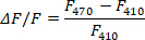
- In the pre-processing section of the fiber photometry system, perform 410 nm as a control for motion correction, set the smoothing coefficient to 8, and choose PLS Fit as baseline correction.
- Calculate the change in fluorescence(ΔF/F) using the formula25:
- Perform astrocyte calcium signal analysis based on event timestamps, extract peri-event data for visualization (e.g., heatmaps and mean traces), and calculate the area under the curve (AUC).
- Synchronized astrocyte-neuron correlation
- Align neuronal spikes and astrocyte calcium signals using the shared behavioral event timestamp as time zero.
- After extracting peri-event data, align the two data streams to this shared time zero and visualize astrocyte-neuron correlation (Figure 3).
Access restricted. Please log in or start a trial to view this content.
Results
Experimental timeline
Figure 1 summarizes the experimental timeline and key surgical landmarks. A three-week interval between viral injection and optrode implantation is critical for achieving adequate GCaMP6s expression, and robust astrocytic calcium signals should be confirmed by examining fiber photometry traces during the baseline recording period before stroke induction.
Multidimensional verification of pho...
Access restricted. Please log in or start a trial to view this content.
Discussion
The integrated protocol described here presents a significant advancement in the study of astrocyte-neuron interactions during ischemic stroke progression. By combining photothrombotic induction with real-time opto-electrophysiological monitoring and optogenetic manipulation, this methodology effectively bridges the gap between stroke onset and the observation of circuit-level reorganization of neurons and astrocytes. Recent work by Boyce et al. demonstrated the feasibility of combined fiber photometry and electrophysiol...
Access restricted. Please log in or start a trial to view this content.
Disclosures
The authors have no conflicts of interest to disclose.
Acknowledgements
This work was supported by the Youth Program of the National Natural Science Foundation of China (No. 82405539), the Basic and Applied Basic Research Fund of Guangdong Province (No. 2023A1515110322, 2025A1515011811), The Youth Talent Support Program of the China Association of Chinese Medicine (2025-QNRC2-B16), Science and Technology Co-construction Project of the National Comprehensive Reform Demonstration Zone for Traditional Chinese Medicine (GZY-KJS-GD-2025-048, GZY-KJS-GD-2025-033), The Special Project for Consolidating the Foundation of Acupuncture and Moxibustion Discipline of Guangzhou University of Chinese Medicine.
Access restricted. Please log in or start a trial to view this content.
Materials
| Name | Company | Catalog Number | Comments |
|---|---|---|---|
| 2% TTC Staining Solution | Solarbio | G3005 | |
| Agorose | Biosharp | BS081 | |
| Body Temperature Maintenance System / Homeothermic Monitor | RWD life Science | 69002 | |
| Cranial Screws | Zhongke Huida | 23092007 | |
| Data Acquisition and Analysis Software(Fiber photometry) | RWD life Science | ORFs | |
| Data Acquisition and Analysis Software(Multi-channel electrophysiology) | Plexon | PlexControl, Offline Sorter, Neuroexplorer | |
| Digital laboratory stereotactic frame | RWD life Science | 68804 | |
| Forcep | FST | 11252-00 | Forcep diameter 0.005 mm ´ 0.025 mm |
| Laser power meter | Sanwa | LP10 | |
| Laser Speckle Blood Flow Imaging System | Pericam AB | Pericam PSI NR | |
| Mice | Risemice | C57BL/6J | |
| Miniature handheld cranial drill | RWD life Science | 78001 | |
| Mouse Viral Micro-injector | RWD life Science | 68025 | |
| Optrode | Customized | Kedou | Customized with 16 tungsten electrode surrounding 1 optical fiber |
| Prism | GraphPad | 5.01 version | |
| R studio | Posit | version 4.4.1 | |
| rAAV-GfaABC1D-GCaMP6s | BrainVTA | PT-2560 | Astrocyte-specific calcium indicator |
| rAAV-GfaABC1D-opto-vTrap | BrainCase | BC-2446 | Astrocyte-specific optogenetic viral vector |
| Rose Bengal Dye | Sigma-Aldrich | 198250 | Photosensitive dye for thrombus induction/Sigma-Aldrich |
| Trolley-mounted anesthesia workstation | RWD life Science | R520 | Anesthesia machine for controllable inhalation anesthesia for mice |
References
- Li, X. Y., et al. Global, regional, and national burden of ischemic stroke, 1990–2021: an analysis of data from the global burden of disease study 2021. EClinicalMedicine. , (2024).
- Zaki, M. G., et al. Non-competitive AMPA receptor antagonist perampanel inhibits ischemia-induced neurodegeneration and behavioral deficits in focal cortical pial vessel disruption stroke model. Cells. , (2025).
- Pu, L., et al. Projected global trends in ischemic stroke incidence, deaths and disability-adjusted life years from 2020 to 2030. Stroke. , (2023).
- Khan, F., et al. Long-term risk of stroke after transient ischemic attack or minor stroke: a systematic review and meta-analysis. JAMA. , (2025).
- Capirossi, C., Laiso, A., Renieri, L., Capasso, F., Limbucci, N. Epidemiology, organization, diagnosis and treatment of acute ischemic stroke. Eur J Radiol Open. , (2023).
- Kumar, S., et al. Addressing systemic complications of acute stroke: a scientific statement from the American Heart Association. Stroke. , (2025).
- Khakh, B. S., Sofroniew, M. V. Diversity of astrocyte functions and phenotypes in neural circuits. Nat Neurosci. , (2015).
- Verkhratsky, A., Parpura, V., Vardjan, N., Zorec, R. Physiology of astroglia. Adv Exp Med Biol. , (2019).
- Chen, W., et al. The role of astrocyte metabolic reprogramming in ischemic stroke (review). Int J Mol Med. , (2025).
- Collyer, E., Blanco-Suarez, E. Astrocytes in stroke-induced neurodegeneration: a timeline. Front Mol Med. , (2023).
- Wang, Y., Wang, D., Li, D., Ma, Y. The role of astrocytes in ischemic stroke — mechanisms, functions and treatment. Front Cell Dev Biol. , (2025).
- Deng, X. P., et al. New insights into acute ischemic stroke from the perspective of spatial omics. Theranostics. , (2025).
- Zhou, Z., et al. Membrane associated RNA-containing vesicles regulate cortical astrocytic microdomain calcium transients in awake ischemic stroke mice. Adv Sci (Weinh). , (2024).
- Mohseni Ahooyi, T. H., et al. Network analysis of hippocampal neurons by microelectrode array in the presence of HIV-1 Tat and cocaine. J Cell Physiol. , (2018).
- Ghouse, M., Li, M., Long, C., Jiang, J. Multichannel extracellular recording in freely moving mice. J Vis Exp. , (2023).
- Montoya, B., Thompson, R. J., Boyce, A. K. J. Simultaneous photothrombosis and fiber photometry to induce and monitor ischemic stroke in behaving mice. J Vis Exp. (225), e69418(2025).
- Labat-gest, V., Tomasi, S. Photothrombotic ischemia: a minimally invasive and reproducible photochemical cortical lesion model for mouse stroke studies. J Vis Exp. (76), e50370(2013).
- Llovera, G., Pinkham, K., Liesz, A. Modeling stroke in mice: focal cortical lesions by photothrombosis. J Vis Exp. (171), e62536(2021).
- Talley Watts, L., et al. Rose Bengal photothrombosis by confocal optical imaging in vivo: a model of single vessel stroke. J Vis Exp. (100), e52794(2015).
- Seong, D., et al. Target ischemic stroke model creation method using photoacoustic microscopy with simultaneous vessel monitoring and dynamic photothrombosis induction. Photoacoustics. , (2022).
- Pochechuev, M. S., et al. Real-time fiber-optic recording of acute ischemic stroke signatures. J Biophotonics. , (2022).
- Gao, Y. K., et al. From disruption to remodeling: the evolution and therapeutic prospects of neuroimmune regulatory circuitry after ischemic stroke. Front Immunol. , (2026).
- Lee, Y., et al. Optrode array for simultaneous optogenetic modulation and electrical neural recording. J Vis Exp. (187), e63460(2022).
- Wang, Y. Q., et al. Protocol for machine learning-based classification of neuronal cell types from spike waveforms. STAR Protoc. , (2025).
- Tian, L., et al. Imaging neural activity in worms, flies and mice with improved GCaMP calcium indicators. Nat Methods. , (2009).
- Boyce, A. K. J., et al. Contralesional hippocampal spreading depolarization promotes functional recovery after stroke. Nat Commun. , (2025).
- Fluri, F., Schuhmann, M. K., Kleinschnitz, C. Animal models of ischemic stroke and their application in clinical research. Drug Des Devel Ther. , (2015).
- Liu, F., McCullough, L. D. Middle cerebral artery occlusion model in rodents: methods and potential pitfalls. J Biomed Biotechnol. , (2011).
- Shvedova, M., et al. Modified middle cerebral artery occlusion model provides detailed intraoperative cerebral blood flow registration and improves neurobehavioral evaluation. J Neurosci Methods. , (2021).
- Bacigaluppi, M., Comi, G., Hermann, D. M. Animal models of ischemic stroke. Part two: modeling cerebral ischemia. Open Neurol J. , (2010).
- Jiang, W., et al. Establishing a photothrombotic “ring” stroke model in adult mice with late spontaneous reperfusion: quantitative measurements of cerebral blood flow and cerebral protein synthesis. J Cereb Blood Flow Metab. , (2006).
- Knezic, A., Broughton, B. R. S., Widdop, R. E., McCarthy, C. A. Optimising the photothrombotic model of stroke in the C57BL/6 and FVB/N strains of mouse. Sci Rep. , (2022).
Access restricted. Please log in or start a trial to view this content.
Reprints and Permissions
