This protocol outlines the clinical and technical workflow for designing and implementing custom 3D-printed implants in orthopaedic surgery, aiming to provide personalized surgical solutions for patients with complex bone loss or deformities where standard implants are insufficient.
Method Article
Three-Dimensional Printed Custom Implants in Orthopaedic Surgery
In This Article
Summary
Abstract
The goal of this protocol is to outline the clinical and technical workflow for the use of custom three-dimensional (3D) printed implants in orthopaedic surgery, particularly in cases of complex bone loss or deformity where standard implants are insufficient. While 3D printing has gained broad medical applications, its role in orthopaedics is especially transformative for patients with pathologies that lack conventional surgical solutions. This manuscript details the step-by-step process, from initial patient evaluation and decision-making to implant design, fabrication, and surgical implantation. Key considerations include patient selection, establishing clear expectations, and engaging in collaborative design with biomedical engineers to ensure optimal implant fit and functionality. The protocol emphasizes the critical role of high-resolution CT imaging, precise computer-aided design (CAD), and advanced manufacturing techniques such as powder bed fusion for metal implants. Post-processing steps, including heat treatment, electrical discharge machining, and surface finishing, are also discussed to highlight quality assurance in implant production. Despite promising early results and the potential for improved outcomes, the use of 3D printed implants remains limited due to elevated initial costs, lack of long-term outcome data, and the individualized nature of each case. Nevertheless, their application offers significant advantages in customization, surgical planning, and functional restoration, underscoring the need for continued research and refinement. This protocol serves as a guide for clinicians considering the integration of 3D printed custom implants into their orthopaedic practice, aiming to expand treatment possibilities for patients with complex reconstructive needs.
Introduction
Three-dimensional (3D) printing has revolutionized orthopaedic surgery by enabling the creation of patient-specific instruments, custom implants, and preoperative anatomical models for surgical planning. This technology allows for rapid prototyping and customization, ultimately leading to enhanced surgical results through improved preoperative planning and personalized surgical solutions using custom implants and instruments. These applications span various medical fields and not just orthopaedics1,2. For example, in cardiothoracic surgery, 3D printing is used to print pulmonary artery models for surgical training, and in the pharmaceutical industry, this technology is used to create drugs with specific properties tailored to patient needs. Generating 3D printed anatomical models has aided the understanding of complex medical conditions, diagnostic accuracy, and directed surgical simulations1. Additionally, the potential for organ printing - also called bioprinting - is immeasurable and will redefine modern medicine.
In orthopaedic surgery, 3D printing technology has greatly improved the ability to care for patients in a multitude of ways. For example, 3D printing has enabled surgeons to create custom prosthetics for patients with limb amputations. This personalization of prosthetics enhances the function of these devices, potentially reducing complications and improving recovery times1. Additionally, 3D-printed anatomical models assist surgeons in preoperative planning, allowing for better visualization and simulation of complex procedures - which can improve patient outcomes. However, one of the biggest areas of advancement in orthopaedics has been the utility of custom 3D printed implants1. A recently published review on 3D printed within orthopaedic surgery found that custom implants in the setting of revision knee arthroplasty had clinical benefits3. Although not common, there are certain orthopaedic pathologies that unfortunately have limited surgical options for management with standard implants and instrumentation. These cases often involve areas of large bone or soft tissue loss1,2. The traditional surgical methods often utilized in these cases carry high complication risks, high failure rates, and even when successful, they often still carry lifelong functional detriments for the patient1,2,4. 3D printing has revolutionized the ability of surgeons to handle these kinds of cases and provided surgical options that were previously unavailable. This manuscript highlights the key steps involved in the design and clinical application of 3D printed custom implants in orthopaedic surgery and discusses a few example cases.
Protocol
All protected health information is excluded from the images and data discussed below. Regardless, patients were informed of the study and the use of their clinical images. Informed consent was obtained. The study adhered to the institution's ethics policy.
1. The patient encounter
- Determine if the patient's pathology is appropriate for a custom 3D printed implant.
- Ensure the patient meets the appropriate criteria for the use of custom implants.
- In order to meet appropriate criteria, ensure there is no readily commercially available standard implant that will adequately treat the patient's pathology and provide optimal functional outcome with low surgical risks
- Complete medical optimization.
- Ensure all medical comorbidities are stable and appropriately managed. For example, patients with diabetes must have a low A1c, and patients with cardiac disease must have appropriate cardiac testing completed to ensure they are safe for surgery.
- Counsel patient/family extensively on custom 3D implants, including the benefits and their drawbacks.
- Obtain a computed tomography (CT) scan of the patient's operative extremity with appropriate parameters.
- Store the files as Digital Imaging and Communications in Medicine (DICOM) files. Critical scan parameters include pixel size of 0.5 mm or less and slice spacing of 1.25 mm or less. Vary the kVp between 100 and 140, depending on the scanner used.
- Capture all relevant anatomy, such as deformed anatomy of bone and the surrounding surgical field in the scan's field of view, including the entire affected and contralateral forefoot, midfoot, and hindfoot up to the mid tibia.
2. Implant design
- Transfer patient imaging, such as a CT scan, to the custom implant manufacturer along with relevant information (i.e., laterality, indication, etc.). Upload the images directly as DICOM files to the implant manufacturers' online portal for CT scan submission.
- Convert patient imaging from 2D CT slices to a 3D model of the preoperative anatomy through segmentation, where bony anatomy is separated from surrounding soft tissue in a mesh-based modeling software such as Materialize Mimics.
- Import DICOM scans into the software.
- Generate a bone mask using the standard bone window.
- Use a region-growing algorithm to select bony anatomy and separate each bone into its own mask.
- Manually remove any non-bony regions included in the mask using the edit mask function.
- Using the split mask function, separate any other bones that were not automatically separated by the region growing algorithm.
- Convert the mask into a part using the Calculate Part function.
- Export each bone as an individual part in an .stl file using the export function.
- Import each bony .stl file into the mesh-based modeling software.
3. Set up initial implant positioning and design within the mesh-based modeling software.
- Mirror contralateral anatomy to match the affected side.
- Align the mirrored contralateral anatomy using a mesh based on alignment of the contralateral to the affected calcaneus.
- Visualize the healthy talus aligned to the unhealthy joint space.
- Idealize/smooth the healthy talus using a proprietary algorithm (restor3d) to create the initial implant body.
- Adjust the positioning of the affected tibia and fibula to reflect the change in joint height with the implant body made from the contralateral talus.
- Conduct an implant design call with the surgeon and engineers to review the segmented 3D anatomy.
- Discuss native deformity and alignment of contralateral anatomy.
- Discuss the talar implant and any patient-specific changes that need to be made.
- Discuss implant sizing (95%,100%, 105% volume).
- Discuss soft tissue attachment sites if needed.
- Finalize implant design computer-assisted design (CAD) file using specialized software (e.g., Materialise 3-matic, SolidWorks).
- Remesh the talar implant using a remeshing feature to optimize triangle size and mesh smoothness.
- Smooth any non-anatomical prominence, such as osteophytes, using local smoothing or a Gaussian smooth option.
- Fill in the bony cavities to increase the material strength of the implant.
- Use local smoothing tools to ensure the articular surfaces of the talar implant match the surrounding articular surfaces.
- Analyze implant mechanical properties (e.g., strength, surface area) using finite element analysis or analytic calculations. Compare predicted performance against physiologic loads expected for the clinical indication and against published benchmarks for 3D-printed Cobalt chromium alloy materials.
- Confirm the cross-sectional area of the implant is above the minimum for material strength.
4. 3D printing process
- Export the finalized implant design CAD file as an STL file from the design software or other compatible format for additive manufacturing input.
- Slicing
- Import the STL file into the 3D printer's native software.
- Define print orientation based on the critical anatomical facing regions of the implant, placing articular surfaces away from the build plate.
- Generate support structures as required for overhanging features.
- Begin the slicing process within the printer's software and convert to G-code instructions.
- 3D printing of an implant
- Manufacture implants using selective laser melting (SLM) or equivalent powder bed fusion technology with Ti-6Al-4V extra-low interstitial (ELI) powder.
NOTE: Typical medical-grade powders have a particle size distribution of 15-45 µm and are processed under an inert argon atmosphere with O2 levels maintained ≤ 1.2 ppm. - Apply scanning parameters optimized by the printer manufacturer (e.g., 3D Systems), including laser type, power, hatch spacing, and layer thickness. Example values reported in the literature include a layer thickness of 30-60 µm, hatch spacing of 100-120 µm, and laser power of 150-300 W, with orientation defined in the z-axis when applicable.
- Utilize a heat source (e.g., fiber laser or electron beam) to selectively fuse metallic powder (particle size 15-45 µm) in an inert argon atmosphere (≤ 1.2 ppm O2), forming the implant layer by layer on the build plate.
- Control relevant parameters, including beam energy density, powder layer thickness, and build plate environment, to ensure dimensional accuracy and mechanical integrity.
- Manufacture implants using selective laser melting (SLM) or equivalent powder bed fusion technology with Ti-6Al-4V extra-low interstitial (ELI) powder.
- Post processing
- Refine implant properties using hot isostatic pressing (HIP) to eliminate residual porosity, relieve stress, and improve microstructure. Typical conditions reported in the literature include ~920 °C at 1000 bar for 120 min in an inert atmosphere.
NOTE: Alternative heat treatments, such as annealing, may be applied depending on the implant material and design. - Remove implants from the build plate using electrical discharge machining (EDM). Cut through the thin base layer of the build using controlled spark erosion, with parameters selected to minimize thermal damage and maintain dimensional accuracy.
- Use hand tools to remove supports used for printing (dremels, hand polisher).
- Apply surface treatments to remove residual powder, fixtures, and adjust roughness. Blast all porous surfaces and hand-polish articular surfaces.
- Perform anodization according to SAE AMS 2488D Type II to enhance corrosion resistance and biocompatibility.
- Refine implant properties using hot isostatic pressing (HIP) to eliminate residual porosity, relieve stress, and improve microstructure. Typical conditions reported in the literature include ~920 °C at 1000 bar for 120 min in an inert atmosphere.
- Perform dimensional inspection of the finished implant using a height gauge and calibrated calipers. When higher precision is required, confirm measurements with a coordinate measuring machine (CMM) against the CAD model.
- Inspect surface finish and porosity visually and by microscopy to ensure accuracy of porous structures and machining features. Confirm surface roughness values (Ra) fall within design specifications for osseointegration and instrumentation interfaces.
- Verify mechanical properties by lot-release testing performed on dogbone specimens printed on the same build plate. Test specimens undergo tensile testing to confirm that the mechanical strength meets published benchmarks for Ti-6Al-4V ELI (or other implant alloy). Record dimensional measurements of test specimens to validate print accuracy.
5. The surgery
- Preoperative work-up
- See patient encounter (step 1)
- Conduct preoperative counseling on the risks and benefits of the surgical procedure.
- Obtain informed consent for the surgical procedure.
- Conduct a preoperative evaluation by the anesthesia team, if necessary.
- Surgical procedure (Total Talus Replacement)
- Place the patient under general anesthesia on the operating table and secure the patient to the table.
- Apply proper padding to all areas of bony prominence.
- Apply a tourniquet to the operative extremity.
- Then, sterile prep and drape the operative extremity.
- Perform a surgical time-out in accordance with hospital policy, confirming the appropriate patient, laterality, and procedure.
- Administer preoperative antibiotics per hospital protocol.
- Use an anterior approach to gain access to the ankle joint, utilizing the interval between the extensor hallucis longus and tibialis anterior tendons.
- Laterally retract the neurovascular bundle carefully and protect it throughout the procedure.
- Identify and open the ankle joint capsule longitudinally.
- Excise the native avascular/damaged talus utilizing saw blade, osteotomes, and ronguers. Care is taken to protect the articular surfaces of the distal tibia, navicular, and calcaneus.
- After removal of the talus, use the sizers to determine the appropriate size of the talar implant to use.
- Once the appropriate size is determined, place the appropriately sized 3D printed implant into the ankle. Confirm appropriate placement with intraoperative fluoroscopy and clinical evaluation.
- Then, irrigate and close the wound in a layered fashion.
- Apply sterile dressings and place the patient in a well-padded splint.
- Postoperative protocol
- Remove sutures at 2-3 weeks postoperatively.
- Begin weight-bearing sessions at 8-12 weeks postoperatively, depending upon the case.
NOTE: Initial weight bearing is in a boot and transition to a regular shoe over several weeks. Physical therapy is optional but recommended for gait training and mobility enhancement.
Results
Generally, long-term representative results for 3D printing in orthopaedic surgery are limited due to the small sample size and the short amount of time that 3D printing in medicine has been utilized. There is some representative data available at this time.
Below are three examples of patients who were treated with 3D printed implants, given meager alternative options for large bone defects or destructive joint pathology. The implants were all designed utilizing the protocol discussed above.
Patient 1
A 43-year-old male presents with a chronic history of left ankle pain. Patient 1 sustained a talar neck fracture that was treated nonoperatively over ten years prior. Radiographs and CT scan imaging shown in Figure 1 and Figure 2 demonstrate talar avascular necrosis with significant sclerosis and fragmentation of the talus. The adjacent joint surfaces are well preserved - but the talus demonstrates significant fragmentation and sclerosis consistent with advanced talar avascular necrosis. The patient was seen at an outside facility and offered an arthrodesis procedure to fuse the subtalar and ankle joints. The patient reports that a full range of motion is required to be able to wear certain shoes for work, and the patient cannot have a fusion of his ankle joint. In discussing options with the patient, we discussed that an alternative is a custom 3D printed total talus. This is a relatively newer surgical option without long-term data; however, this option allows for preservation of his joints and range of motion. We discussed extensively the risks associated with this procedure and the lack of long-term data. However, the patient expressed to us that fusion is not an option. After extensive discussion, the patient elected to proceed with a custom 3D printed total talus replacement. In this patient's case, we elected to use a Titanium alloy for the implant material. This material has similar biomechanical properties to native bone and has optimal wear properties to decrease the risk of damage to surrounding cartilage.
The talus is designed to mirror the patient's contralateral talus, which is normal without disease. Postoperative imaging obtained at his postoperative appointment at 6 weeks is shown in Figure 3. The patient reports that he is ambulating well postoperatively, without pain, and has shown improvements in his functional level. Patient reports that his range of motion has increased postoperatively, and he has approximately 10 degrees of dorsiflexion with 35 degrees of plantar flexion.
Patient 2
A 20-year-old female presenting with left foot pain and swelling secondary to a known giant cell tumor of the first metatarsal. Patient was initially treated with saucerization and bone grafting - a procedure that involves scraping out the tumor and replacing it with bone material. Radiographs and CT scan imaging (Figure 4 and Figure 5) demonstrated an expansile lytic lesion centered within the first metatarsal, compatible with biopsy-proven giant cell tumor. Due to persistent symptoms with activity and aggravation with shoe wear, the patient wished to proceed with surgical resection of the entire metatarsal. She had tried less invasive and local procedures in the past that had not worked. Surgical resection of the metatarsal is a large procedure, and the challenge comes with the reconstruction of the resected area.
While meeting with the patient, we discussed her options, which included replacing the entire metatarsal bone with a 3D printed bone or using bone harvested from her leg, which would be a fibula autograft. We discussed the risks of fibula grafting, including graft site morbidity and the high risk of nonunion. Another option is a partial amputation of her foot, which she was not interested in. After extensive discussions with the patient and her family over several visits, she elected to proceed with a 3D printed custom implant. A custom metatarsal cage can maintain the patient's length and anatomy, provide a more mechanically robust construct than autograft, and does not carry the donor site morbidity associated with free fibula harvest. Preoperative designs created through the design call with engineers are shown in Figure 6. This procedure was performed with the orthopaedic oncology team to ensure the resection was performed appropriately. Pictures of the implant on the day of surgery are shown in Figure 7. Like patient 1, the implant material chosen is a titanium alloy, which is similar in biomechanical properties to cortical bone.
Postoperatively, she was kept non-weight-bearing for a total of 12 weeks. She began weight bearing at 12 weeks in a boot and gradually progressed out of the boot by 4 months. Postoperative X-ray (Figure 8) imaging obtained at 3 months demonstrated no evidence of hardware failure with some bony integration of her implant. At her 6-month visit, she had completely weaned out of the boot and started her low-impact activities. A CT scan obtained at the 6-month visit demonstrated that her implant had good bony contact and stability with some integration of the bone onto the implant (Figure 9). She is over a year out from her surgery and walking pain-free in regular shoes.
Patient 3
A 34-year-old female presents with 7 years of chronic right ankle pain secondary to osteonecrosis of the talus and subsequent collapse of the talar dome. Her preoperative radiographs are shown in Figure 10. She also demonstrated evidence of osteonecrosis of the tibial plafond and calcaneal body with marked osteoarthrosis of the tibiotalar and subtalar joint. This was believed to be secondary to chronic high-dose steroid use during prolonged hospitalization in the past.
Overall, she was significantly limited in her daily activities due to the chronic pain in the right ankle. She had attempted conservative management with prolonged physical therapy, activity modifications, and pain medications prescribed by her primary care provider. We discussed her surgical options given her persistent symptoms. Based on her imaging, we discussed that an isolated ankle fusion would not likely be a good option for her, given her talar collapse and her subtalar arthritis. We discussed that the best surgical solution is tibiotalocalcaneal (TTC) arthrodesis. However, the challenge in her case is the significant joint height loss due to her talar collapse, but also the large bony void that will remain after excision of the unhealthy talar bone. Structural grafting can be performed using a femoral head allograft; however, there are high rates of graft subsidence and failure reported in the literature. Furthermore, it is challenging to ensure that we restore her height as the allograft can be difficult to shape appropriately and may not fit perfectly. Another option is a 3D printed custom cage. The metal cage can maintain height and anatomy without the risk of graft subsidence and is a mechanically strong construct. After extensive discussion, she elected to proceed with a TTC arthrodesis with a 3D printed custom cage construct. Again, the cage is created out of a titanium alloy, which has similar biomechanical properties to bone. This is chosen to mimic the natural biomechanical environment for bone growth in the cage. Postoperative imaging taken at 3 months is shown in Figure 11. Her ankle joint height is restored with the implant, and there is good bony integration at the implant-bone interface.
She was kept non-weight-bearing for 12 weeks. She then began walking in a boot and transitioned to a show by 4 months. By 6 months, the patient was walking pain-free and at 1-year follow-up had no functional deficits due to her ankle. She is no longer limited by the ankle and is far more active than she was prior to the operation.
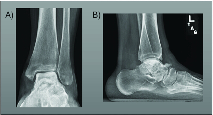
Figure 1: Preoperative X-rays of Patient 1. (A,B) Preoperative mortise (A) and lateral (B) X-rays of the left ankle for Patient 1. Radiographs demonstrate significant talar avascular necrosis with sclerosis and fragmentation of the talus. Please click here to view a larger version of this figure.
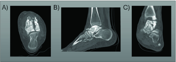
Figure 2: Preoperative CT of Patient 1. (A-C) Preoperative axial (A), sagittal (B), and coronal (C) CT Imaging of the left ankle for Patient 1. CT scan imaging demonstrates significant talar avascular necrosis with sclerosis and fragmentation of the talus. Please click here to view a larger version of this figure.
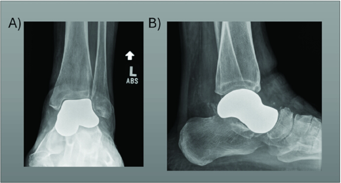
Figure 3: Postoperative X-rays of Patient 1. (A,B) Postoperative AP (A) and mortise (B) X-rays of the left ankle for Patient 1 taken at 6 weeks postoperative appointment. Radiographs taken at 6 weeks demonstrate appropriate alignment and placement of the talus implant. Please click here to view a larger version of this figure.
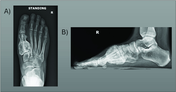
Figure 4: Preoperative X-rays of Patient 2. (A,B) Preoperative weight-bearing AP (A) and lateral (B) X-rays of the right foot of Patient 2. Radiographs demonstrate a large bony expansile lesion of the first metatarsal. Please click here to view a larger version of this figure.
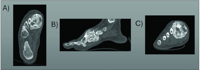
Figure 5: Preoperative CT of Patient 2. (A-C) Preoperative axial (A), sagittal (B), and coronal (C) CT Cuts of the right foot of Patient 2. The CT scan of the patient demonstrates the lesion. Please click here to view a larger version of this figure.
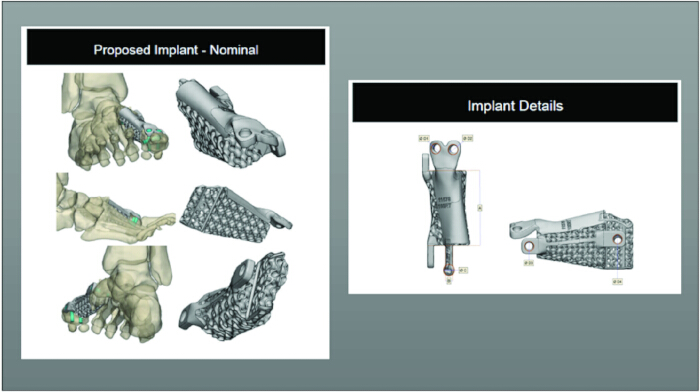
Figure 6: Designs of the implant prior to 3D printing. These are examples of the design phase of the implant, where engineers create schematics of the implant using the patient's CT scan imaging. The implant is fixed to the metatarsal head with screws that are placed into the implant. The implant is secured to the medial cuneiform with a keel. Please click here to view a larger version of this figure.
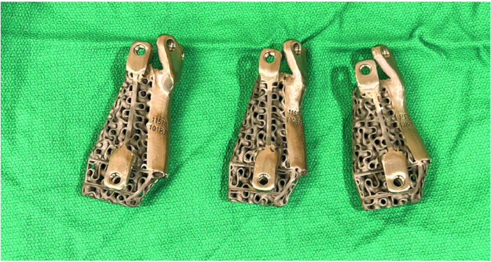
Figure 7: Clinical pictures of the three implant sizes. There are three sizes printed for the case, each with 5% variation in volume. The reason for this is to account for any intraoperative variation and variation in the CT scan with respect to the actual patient anatomy. Please click here to view a larger version of this figure.
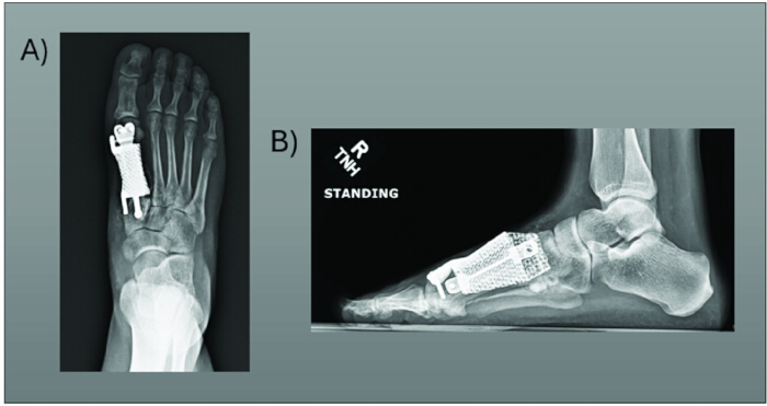
Figure 8: Postoperative X-rays of Patient 2. (A,B) Postoperative Weightbearing AP (A) and Lateral (B) X-rays of Patient 2. Radiographs taken at three months postoperatively demonstrate hardware in the appropriate place with good alignment and good bony apposition between the implant and native bone. Please click here to view a larger version of this figure.
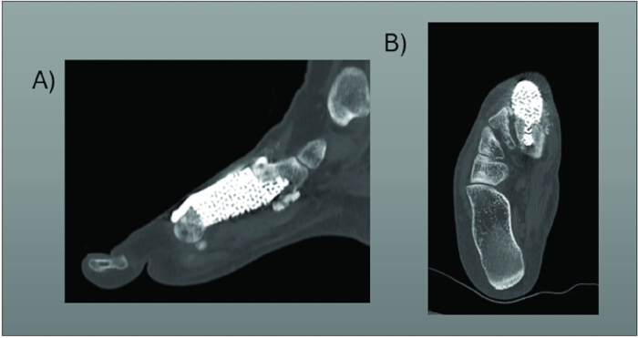
Figure 9: Postoperative CT of Patient 2. (A,B) Postoperative CT scan sagittal (A) and axial (B) imaging demonstrates stable hardware and good bony apposition at the interface of the bone to implant, with bone formation and integration of the implant to the native bone. This CT scan was obtained at 6 months postoperatively. Please click here to view a larger version of this figure.
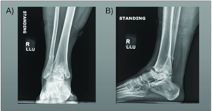
Figure 10: Preoperative radiographs of Patient 3. (A,B) Preoperative AP (A) and lateral (B) radiographs of the right ankle of Patient 3. The patient has significant talar collapse and ankle and subtalar joint arthritis. Please click here to view a larger version of this figure.
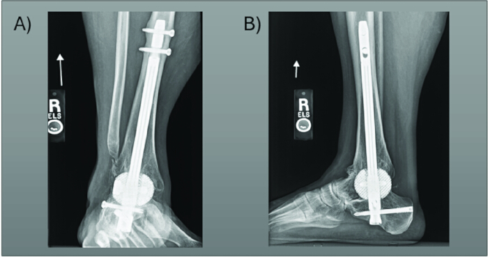
Figure 11: Postoperative radiographs of Patient 3. (A,B) Postoperative AP (A) and lateral (B) radiographs of the right ankle of Patient 3. Radiographs obtained at the patient's 6-month follow-up demonstrate that the hardware is in place with good bony apposition at the fusion sites. Her ankle joint height is restored. Please click here to view a larger version of this figure.
Discussion
Custom 3D printed implants in orthopaedic surgery are not common; however, their utility in challenging cases is demonstrated in the above cases. For these patients, without 3D printing, the surgical solutions are quite limited, and even the best available options carry high risk and functional consequences. There are many important steps to consider in the process of designing custom implants. The first and foremost is whether the case is appropriate for custom implants. This involves thoughtful consideration of all the alternatives and their pros and cons. It is important to involve the patient and family in these discussions. Custom 3D implants are newer with limited literature, and it is imperative to educate patients on their experimental nature.
The second most critical step in the process is implant design. The surgeon must consider several factors, including implant sizing, surgical approach, necessary instrumentation for implant placement, and the surgical goals. This involves counseling surgeons who have experience in 3D printing, but also working with engineers on design calls to create the design of the implant. Once implant production is underway, there is limited room for modification; thus, the design phase is crucial.
Despite the promising potential of 3D printing in orthopaedic surgery, several challenges remain. A significant limitation is the high cost associated with the technology. Implants can range in cost from $14,000 to $20,000 for our implants, depending upon the complexity of the case. However, as 3D printing technology continues to evolve, it is anticipated that production costs will decrease over time1. Another key limitation is the lack of long-term data on outcomes. A recently published retrospective, multi-center study evaluated the safety of 3D printed talus replacements for the treatment of avascular necrosis4. In their study, they had a total of 15 patients with at least 1 year of follow-up and determined that early results were promising with good outcomes. Adams et al. demonstrated similar safe outcomes with 3D printed cages for large bone defects5. In their study, they compared eight patients who underwent surgery with a custom cage to seven who underwent surgery with large cadaver allograft bone. Kadakia et al.6 evaluated the outcomes of total talus arthroplasty in 22 patients over a 2-year span. They noted significant functional improvements with short-term follow-up. Interestingly, there are a few studies evaluating long-term outcomes following total talus arthroplasty from centers in Japan. In these two studies, they have over 10-year post-op follow-up and found that patients had good patient-reported outcomes following either a total talus replacement or just a talar body replacement7,8. It is important to note that these implants were not custom or 3D printed and were ceramic; thus, this data does not translate to current total talus replacements that are metal and custom. Regardless, it is interesting to note that this procedure and concept have been around for quite some time, but are just becoming more popular in use for the management of severe talar pathology. Although the focus of this manuscript has been lower extremity cases, the applications of 3D printing in orthopaedics have expanded to many subspecialties2. Malunited distal radius fractures can have severe functional consequences for patients, and the corrective osteotomies needed to correct this deformity are very challenging due to the many planes of correction that must be taken into consideration. The same can be said for forearm fractures that heal incorrectly, as there are rotational forces that must be considered. Several recently published studies have found that custom 3D printed cut guides and instrumentation can assist in these challenging upper extremity cases of deformity correction9,10.
It is important to note that despite the promising results of custom 3D printed implants and instrumentation, most recently published studies have very small sample sizes with short-term follow-up6,7,8. Few studies have demonstrated the extended-term outcomes of 3D-printed implants, and further research is needed to assess their durability and effectiveness in the long run. Some of this can be attributed to the fact that this technology is relatively new and that the pathology indicated for 3D printing is not common. Additionally, due to the highly customizable nature of these implants, generalizing results across different cases is very challenging.
Regardless, the potential benefits of 3D printing are clear with the above examples and available literature. One of the most compelling advantages is the ability to replicate human anatomy in unique ways that were previously impossible. Customization allows implants to be tailored precisely to individual patients, enabling a direct match to the surgical need. With the continuous advancements in CT imaging and 3D printing technologies, implants are becoming increasingly accurate, durable, and cost-effective1,2.
Overall, 3D printing remains a rapidly developing technology, offering a growing range of possibilities in orthopaedic surgery. As technology matures, future applications may include the development of more intricate, interconnected structures. As we gain proficiency with single-bone and joint implants, the next logical step is to explore the creation of more complex, multi-component implants. While current implants predominantly utilize biocompatible metal alloys, another major step in 3D printing would include future innovations in soft tissue reconstruction, such as bioprinting to create cartilage11. 3D printing is an exciting field of technology that is constantly evolving, and its application in orthopaedic surgery will continue to grow and adapt as this technology changes.
Disclosures
Authors have no relevant disclosures or conflicts of interest.
Acknowledgements
There are no additional sources of funding for acknowledgement.
Materials
| Name | Company | Catalog Number | Comments |
|---|---|---|---|
| Metatarsal titanium cage implant | Restor3D | https://www.restor3d.com/ | Custom implant; Titanium Alloy (Ti-6Al-4V) |
| Spherical titanium cage implant | Restor3D | https://www.restor3d.com/ | Custom implant; Titanium Alloy (Ti-6Al-4V) |
| Total Talus Replacement | Restor3D | https://www.restor3d.com/ | Custom implant; Titanium Alloy (Ti-6Al-4V) |
References
- Wixted, C. M., Peterson, J. R., Kadakia, R. J., Adams, S. B. Three-dimensional printing in orthopaedic surgery: current applications and future developments. J Am Acad Orthop Surg Glob Res Rev. 5 (4), e20.00230-11(2021).
- Aimar, A., Palermo, A., Innocenti, B. The role of 3D printing in medical applications: a state of the art. J Healthc Eng. 2019, 5340616(2019).
- Qu, Z., Yue, J., Song, N., Li, S. Innovations in three-dimensional-printed individualized bone prosthesis materials: revolutionizing orthopedic surgery: a review. Int J Surg. 110 (10), 6748-6762 (2024).
- Abar, B., et al. Initial safety of total talus replacement used to treat talar avascular necrosis. Foot Ankle Int. 45 (11), 1258-1265 (2024).
- Steele, J. R., Kadakia, R. J., Cunningham, D. J., Dekker, T. J., Kildow, B. J., Adams, S. B. Comparison of 3D printed spherical implants versus femoral head allografts for tibiotalocalcaneal arthrodesis. J Foot Ankle Surg. 59 (6), 1167-1170 (2020).
- Kadakia, R. J., Akoh, C. C., Chen, J., Sharma, A., Parekh, S. G. 3D printed total talus replacement for avascular necrosis of the talus. Foot Ankle Int. 41 (12), 1529-1536 (2020).
- Taniguchi, A., et al. An alumina ceramic total talar prosthesis for osteonecrosis of the talus. J Bone Joint Surg Am. 97 (16), 1348-1353 (2015).
- Harnroongroj, T., Harnroongroj, T. The talar body prosthesis: Results at ten to thirty-six years of follow-up. J Bone Joint Surg Am. 96 (14), 1211-1218 (2014).
- Raad, F., Harmsen, K., Beeres, J. P., Schep, N. W. Outcome of corrective osteotomies of the distal radius using three-dimensional-printed patient-specific implants. J Hand Surg Eur Vol. , (2025).
- Schindele, S., Oyewale, M., Marks, M., Brodbeck, M., Herren, D. B. Three-dimensionally planned and printed patient-tailored plates for corrective osteotomies of the distal radius and forearm. J Hand Surg Am. 49 (3), 277.e1-277.e8 (2024).
- Pantermehl, S., et al. 3D printing for soft tissue regeneration and applications in medicine. Biomedicines. 9 (4), 336(2021).
Reprints and Permissions
This article has been published
Video Coming Soon