Here we describe a method using an inexpensive stereolithographic 3D printer to create molds to facilitate the reproducible mounting of zebrafish embryos for imaging studies. Using this method, we have created molds for imaging cardiac morphogenesis in zebrafish embryos.
Method Article
Custom 3D-Printed Molds for Zebrafish Imaging and Cardiac Development
Opens in a new tab
In This Article
Summary
Loading...
$$\rightleftharpoonup{xx}$$
$$\longleftharp{xx}$$,
$$\longrightharp{xx}$$,
Abstract
Loading...
$$\rightleftharpoonup{xx}$$
$$\longleftharp{xx}$$,
$$\longrightharp{xx}$$,
Embryo mounting is one of the technical challenges researchers encounter when undertaking an imaging project. Embryos need to be oriented in a reproducible manner such that the tissue of interest is accessible to a microscope objective for the entire imaging period. To overcome this challenge, researchers can embed embryos in viscous media or create specialized dishes and casts to hold embryos in a desired orientation during imaging. Here, we describe a method for using an inexpensive stereolithographic (SLA) 3D-printer to manufacture reusable molds that create agarose wells in which embryos can be mounted for imaging. These agarose wells provide a reliable means for orienting multiple embryos for imaging. This method includes a design framework that can be easily customized for a variety of tissues, organisms, and imaging challenges. Using this method, we have created molds for imaging cardiac development in zebrafish for both upright and inverted microscopes. By utilizing materials and equipment that are accessible, this method allows researchers to easily create molds specific to their mounting needs.
Introduction
Loading...
$$\rightleftharpoonup{xx}$$
$$\longleftharp{xx}$$,
$$\longrightharp{xx}$$,
Visualizing cellular dynamics within an intact animal is essential for comprehending the pathologies of congenital diseases and the fundamental processes of development and homeostasis. This visualization encompasses imaging at multiple spatial scales to identify physiological dynamics across an entire organism as well as at the tissue, cellular and sub-cellular levels. The imaging modalities used for visualizing cellular dynamics range from immunofluorescence studies of fixed specimens to time-lapse imaging of live specimens. These imaging modalities require holding intact specimens in specific orientations, such that a region of interest is accessible to the microscope objective.
Zebrafish embryos are an ideal model organism for imaging studies due to their optical transparency, genetic tractability, external fertilization and vertebrate origin. However, mounting zebrafish embryos in a specific orientation in a consistent and reproducible manner has represented a continual challenge. Mounting is especially challenging for the visualization of heart development in zebrafish embryos because cardiac morphogenesis occurs in different planes1.
Multiple approaches have been developed to address the challenges of mounting embryos for imaging. One of the simplest methods involves mounting zebrafish embryos between two coverslips with layers of tape in between the coverslips to prevent crushing. This method allows for imaging on both inverted and upright microscopes2. Zebrafish embryos can also be mounted in a highly viscous media or gel, such as methylcellulose or 0.1-0.8% low-melting-point temperature agarose, to hold embryos in specific orientations2,3,4. These low-throughput approaches work well for many imaging projects; however, ensuring embryo integrity and reproducibly obtaining specific orientations can be troublesome. To increase imaging throughput and facilitate mounting, regularly spaced wells can be created from solidified agarose in an imaging dish5,6,7,8. To facilitate the creation of these agarose wells, plastic molds have been created9,10,11. While these molds can be applied to imaging along the standard dorsal-ventral-lateral axes10,12, they are often made for specific imaging challenges, such as for use in 96-well plates13 or for the detection of the first heartbeat14. In specialized cases, entire imaging dishes have been created5,15,16. For example, a microfluidic chamber (named ZEBRA) made out of PDMS facilitates both imaging and exposure of embryos to chemicals17. These molds are often made from silicone or machined from lucite10,18,19. However, the advent of relatively inexpensive three-dimensional (3D) printers has democratized the creation of customized molds that are used to create agarose imaging wells.
3D printing, also called additive or layered manufacturing, involves producing a 3D object from a digital design by the sequential addition and fusion of individual layers20,21. Stereolithography (SLA) utilizes ultraviolet (UV) light to cure a light-sensitive liquid resin in sequential layers22. SLA printers are cost-effective, fast, and highly accurate and can be used with a variety of resins, including those that deliver a smooth surface16. The process begins with computer-aided design (CAD) software, where digital models of the object can be designed de novo or modified from preexisting designs. The digital model is then virtually sliced into printable layers. Using these digital layers, a 3D printer constructs the object, layer by layer. Here, we present a method and framework for the custom design and creation of imaging molds using a low-cost commercially available SLA 3D-printer. Additionally, we use this framework to create molds for imaging different stages of zebrafish cardiac development on either inverted or upright microscopes and for imaging zebrafish embryos along their lateral, dorsal, or ventral axes.
Protocol
Loading...
$$\rightleftharpoonup{xx}$$
$$\longleftharp{xx}$$,
$$\longrightharp{xx}$$,
The protocols, experiments, and findings described here were conducted in accordance with animal welfare regulations and guidelines, and the Institutional Animal Care and Use Committee at the University of Mississippi (protocol #24-008).
To create agarose wells of different shapes in which embryos can be oriented for imaging, we developed a design that utilizes a base attached to pegs (Figure 1A). The shape of these pegs (see arrow pointing to pegs in purple in Figure 1A) can be customized to orient embryos of different developmental stages and to focus on different tissues. Below, we describe a protocol for customizing these pegs and for using this system to create agarose wells.
1. Creating a custom-designed imaging mold
- Create a preliminary sketch of the specimen or embryo positioned in the desired orientation. Consider the desired embryo orientation and whether the microscope to be used contains upright or inverted objectives. Also consider the size of the dish, the number of embryos to be mounted, and the spacing between them.
- Measure embryo dimensions (e.g., length, width, and height) using a microscope combined with a software tool such as FIJI23. Use these dimensions to ensure that the embryos fit into the wells created by the pegs.
- Identify a shape that corresponds to the embryo's geometry. Using the measurements from step 1.2 in combination with a computer-aided design (CAD) software create a peg that approximates the shape and size of the sample.
NOTE: This shape can be created in a basic CAD software program by combining and overlapping different predesigned shapes, or the shape can be created de novo using an advanced CAD software program. Additionally, one can modify one of our predesigned pegs (see Supplemental File 1). Tapering the peg, as in Figure 1A, can help orient embryos to ensure the tissue of interest is closest to the objective. - Combine peg design with base design:
- In a CAD software program, add a custom-designed peg to one of the predesigned bases (Supplemental File 1). Then, duplicate and evenly place the pegs throughout the base for high-throughput imaging by using the tools in an advanced CAD program. Double check to ensure all pegs reach the same height away from the base.
- Prepare the design for 3D printing:
- Transfer the customized mold design or one of the pre-designed molds (Supplemental File 2) to a slicer software, which converts the design into commands for the 3D printer.
- Within the slicer software, be sure to rotate the design so that critical components such as the pegs are positioned away from the printer stage. For the coverslip holder, which is printed on a fused deposition modeling (FDM) printer, position the print horizontally.
NOTE: Rotation of the design will prevent warping, which can happen when delicate parts are positioned close to the printing stage. - Add supports within the slicer software to ensure that delicate aspects of the mold do not break during the printing. The medium automatic support placement feature in the software along with manual curation ensures a good spread of supports without large gaps. A 100% infill strategy is used to create a solid mold.
- Print multiple pieces simultaneously by either using a single STL file containing all molds or arranging individual STL files together using the slicer software.
- Printing
NOTE: SLA printers are our preferred 3D printer type for the imaging molds due to their feasibility, precision, and their creation of smooth surfaces. An FDM printer is used to make the coverslip holder because it creates lightweight, stiffer prints than SLA printers.- Start with the following print settings and optimize from there: 0.05 mm layer height; 5 bottom layer count; 2.5 s exposure time; 35 s bottom exposure time; 5 mm bottom lift and lifting distance; 60 mm/min bottom lift speed; 80 mm/min lifting speed; and 210 mm/min retract speed.
NOTE: The print settings will likely need to be optimized by the user as they depend on resin type, room temperature, and model of printer.
- Start with the following print settings and optimize from there: 0.05 mm layer height; 5 bottom layer count; 2.5 s exposure time; 35 s bottom exposure time; 5 mm bottom lift and lifting distance; 60 mm/min bottom lift speed; 80 mm/min lifting speed; and 210 mm/min retract speed.
- After printing, wash the molds in water, remove the supports, and place the molds under UV light in a tissue culture hood to ensure the solidification of the resin.
NOTE: Washing and curing the molds thoroughly is important for preventing resin from flaking off and for preventing the mold from becoming misshapen.
Gloves and a lab coat should be worn when handling uncured resin and cleaning the molds, since uncured resin can be a skin irritant. SLA printers use UV light to cure the resin, which can be harmful to the eyes and skin. Ensure that the print chamber is securely enclosed and avoid looking directly at the UV light source.
2. A procedure for using 3D-printed molds to create agarose wells
- Making agarose wells
- Make agarose wells by dissolving 2% (g/mL) agarose in E3 media (1.578 mM NaCl, 0.169 mM KCl, 0.249 mM CaCl2*2H2O, 0.161 mM MgSO4*7H2O). Place a mold in the center of a coverslip bottom dish with the arrow pointing down towards the well (see Figure 2A,B). Pipette 750 µL of 2% molten agarose/E3 along half of the imaging mold's perimeter (see Figure 2C).
NOTE: Molten agarose should be non-viscous but cool enough to pipette without creating bubbles. We use 60 mm dishes with a 30 mm coverslip bottom well, while for molds designed for upright microscopes, a standard 60 mm dish can be used. A slightly different protocol is used for the screening mold (see below). - Pipette another 750 µL of 2% molten agarose/E3 along the other half of the imaging mold's perimeter (see Figure 2D).
- Wait 5-7 min for the agarose to solidify, observing the transition from a clear liquid to an opaque blue gel (see Figure 2E).
- Add a thin layer of molten agarose around the perimeter of the solidified central agarose.
NOTE: Although not strictly required, this step helps anchor the solidified agarose to the dish and prevent media-induced detachment. - Place the outer ring (Supplemental Figure S1B) over the agarose mold assembly with the arrow pointed towards the agarose (see Figure 2F).
- While gently holding down on the outer ring, carefully pull straight up on the inner mold to detach it from the agarose (see Figure 2G).
NOTE: To avoid breaking or damaging the agarose wells, do not push down too hard on the outer ring and do not twist or shift the inner mold when pulling upwards. - Remove the outer ring, revealing the agarose wells in the coverslip bottom dish (Figure 2H).
- Inspect the agarose wells under a microscope to confirm correct sizing and production.
NOTE: For imaging on an inverted microscope, a thin film of agarose often needs to be lifted off the bottom of the well. This can be done with forceps.
- Make agarose wells by dissolving 2% (g/mL) agarose in E3 media (1.578 mM NaCl, 0.169 mM KCl, 0.249 mM CaCl2*2H2O, 0.161 mM MgSO4*7H2O). Place a mold in the center of a coverslip bottom dish with the arrow pointing down towards the well (see Figure 2A,B). Pipette 750 µL of 2% molten agarose/E3 along half of the imaging mold's perimeter (see Figure 2C).
- Modified protocol for using the screening mold
- Pour molten 2% agarose/E3 into the Petri dish until it is approximately halfway full.
- Hold the mold with the pegs facing upwards and pipet molten 2% agarose/E3 onto the pegs, until they are covered (~3 mL).
NOTE: Ensure that bubbles are not introduced by releasing only 90% of the molten agarose that has been drawn into the pipet. - Using a tilting motion, place one end and then the whole mold with pegs face down into the Petri dish containing molten agarose (Supplemental Figure S2).
- Allow the agarose to solidify for 5-7 min.
- Carefully remove the mold by using the handle to pry up one end and then the other end.
3. Mounting embryos in agarose wells with and without low-melting temperature agarose
- Dechorionate and anesthetize embryos in a 200 μg/mL tricaine solution prior to mounting.
NOTE: An ~400 μg/mL tricaine solution is required to stop the heart from beating.- Without using low-melting-temperature agarose: Fill the imaging dish with 1x E3 and tricaine (200 μg/mL), add dechorionated anesthetized embryos to the imaging dish, use forceps to place and orient embryos in the agarose wells, and then image (see Figure 2I, J).
NOTE: Because forceps can easily damage an embryo, an embryo poker in which 0.41 mm diameter fishing line is inserted into a capillary tube or pipette tip and secured with superglue can be used instead24. - Using low melting temperature agarose:
NOTE: While the molds are designed to place embryos in specific orientations, using low melting temperature agarose to hold embryos in place can ensure that embryos do not drift during imaging or while transporting the imaging dish with the mounted embryos to the microscope. The steps below are derived from our previous protocol6.- Create tubes of low-melting-temperature agarose by dissolving 0.1-0.8% low-melting-temperature agarose in 5 mL of E3 media and heating to 65-70 °C in a water bath. Occasionally, invert the tube until the low-melting-temperature agarose has dissolved. Aliquot the low-melting-temperature agarose solution into microfuge tubes and place them on a heat block set to 42 °C. Allow the solution to equilibrate to 42 °C for at least 1 h.
NOTE: It is generally advisable to use a freshly made low-melting temperature agarose solution. - Using a wide-bore glass Pasteur pipette, transfer a single embryo into a tube containing the low-melting temperature agarose solution. To avoid adding excess liquid to the low-melting temperature agarose solution, only transfer the embryo and liquid immediately surrounding it. Immediately transfer the embryo, which is now in low-melting agarose, to one of the agarose wells. Return the low-melting temperature agarose solution to the heat block for re-use.
- Using forceps or an embryo poker (see step 3.1.1), position the embryo in the well for imaging.
- Repeat steps 3.1.2.2-3.1.2.3 for the other wells. If the previous wells begin to dry out, use a p200 pipet to add a small amount of E3 (~50-100 μL) on top of the well.
- Create tubes of low-melting-temperature agarose by dissolving 0.1-0.8% low-melting-temperature agarose in 5 mL of E3 media and heating to 65-70 °C in a water bath. Occasionally, invert the tube until the low-melting-temperature agarose has dissolved. Aliquot the low-melting-temperature agarose solution into microfuge tubes and place them on a heat block set to 42 °C. Allow the solution to equilibrate to 42 °C for at least 1 h.
- Without using low-melting-temperature agarose: Fill the imaging dish with 1x E3 and tricaine (200 μg/mL), add dechorionated anesthetized embryos to the imaging dish, use forceps to place and orient embryos in the agarose wells, and then image (see Figure 2I, J).
- Once embryos have been mounted in all wells and the low-melting temperature agarose has solidified, using a pipet slowly add the tricaine/E3 solution to the imaging dish.
- After imaging, extract the embryos carefully from the wells using forceps and allow them to develop further to ensure imaging did not cause developmental defects.
NOTE: The agarose wells can be removed from the imaging dish, which can be rinsed and reused. Rinsing with commercially available glass cleaner and then multiple times with ddH2O helps to remove salt deposits on the coverslips. Although we have not experienced toxicity due to residual traces of glass cleaner, the researcher is advised to confirm these results using their own laboratory conditions.
Results
Loading...
$$\rightleftharpoonup{xx}$$
$$\longleftharp{xx}$$,
$$\longrightharp{xx}$$,
The above protocol was used to design molds for imaging different stages of cardiac development in zebrafish, including cardiac fusion, heart tube formation, cardiac looping and chamber formation. Since cardiac development does not occur along the major anatomical axes of the embryo, the shape of the pegs were customized for different developmental stages in order to properly position the embryos. For example, the anterior inner placement of the zebrafish heart at 48 hours post-fertilization (hpf) relative to the spherical yolk requires a sloped embryo orientation which was facilitated by creating pegs with tapered edges in mold V2 (Figure 1A,B). Utilizing mold V2 to create agarose wells for imaging with an inverted confocal microscope we used the Tg(myl7:egfp) transgene25 to compare the cardiac morphology between a wild-type embryo and a severe pdgfrask16/sk16 mutant embryo26 displaying cardia bifida at 48 hpf (Figure 1C,D). To image early events in heart development, such as cardiac fusion and lumen formation, using an upright stereo microscope, the Standing (ST) mold was designed to create a well for the zebrafish trunk (Figure 1E-H). This places the dorsal anterior side of the embryo directly under the objective of an upright microscope, allowing for these early stages of heart development to be visualized. During later stages of heart development, the heart is positioned on the ventral side of the embryo. For imaging these stages with an upright microscope, the Halfway (HW) mold was designed to create a shallow agarose trough to hold embryos on their dorsal side (Figure 1I,J), facilitating imaging of cardiac looping and chamber development (Figure1K-M). Agarose wells created by the HW mold were also used to mount and image four immobilized live embryos over 12 h (60-72 hpf, Supplemental Figure S3). Cardiac development proceeded normally during this time and the embryos were healthy and viable for >24 h afterwards. During this imaging session, no degradation in the shape of the agarose wells was observed. Altogether three molds for imaging cardiac development with an inverted microscope have been designed and printed (Figure 1A and Supplemental Figure S4B-D) and two molds were designed for imaging cardiac development with an upright microscope (Figure 1E,I and Supplemental Figure S4E,F).
Additionally, molds for imaging zebrafish embryos along the lateral, dorsal or ventral axes of the embryo with an inverted microscope were created. These molds include a mold that orients zebrafish embryos in a lateral position for visualizing the zebrafish trunk (Figure 1N,O). With this mold we imaged zebrafish trunks stained with the fluorescently conjugated lectins Ricinus Communis Agglutinin (RCA-120) and Wheat Germ Agglutinin (WGA), which preferentially bind to terminal β-linked galactose, or N-acetylglucosamine (GlcNAc)- and sialic acid-containing glycans27, respectively. Galactose-containing glycans as detected by RCA-120 staining were observed to be enriched in the myoseptal junctions (Figure 1P), whereas either GlcNAc- or sialic acid-containing glycans as detected by WGA staining were observed to be enriched in the notochord (Figure 1Q). WGA can bind to both GlcNAC- and sialic acid-containing glycans27,28,29,30. The lateral mold was also used to conduct time-lapse studies of intersomitic blood vessel (ISV) formation (Figure 1R-V'). Using the Tg(fli1a:eGFP) transgene31, we created time-lapse movies with a temporal resolution of ~3 min, in which we observed filopodia formation (Figure 1R-V' and Supplemental Video S1), as previously reported32. These general molds (see Supplemental Figure S4A,G-I) are designed for the imaging of 10-96 hpf zebrafish embryos along the ventral, dorsal and lateral axes. We have also designed a mold for routine phenotypic and transgenic screening of 24-72 hpf embryos with an upright microscope (Supplemental Figure S1A). And we have designed a coverslip holder for the mounting technique that utilizes two coverslips2 (Supplemental Figure S1C). We created the coverslip holder with a fused deposition modeling (FDM) printer because these printers create stiffer, lightweight products, and the smooth surfaces created by SLA printers are not needed for this holder33.

Figure 1: Customization of 3D-printed molds for specific tissues and imaging challenges. We have designed and printed molds to facilitate the mounting and imaging of different zebrafish tissues, including the (A-M) heart and (N-V') the trunk. These molds are useful for multiple different imaging experiments, including (A-D) analyzing mutant embryos with an inverted confocal microscope, (E-M) comparing cardiac morphology at different developmental timepoints with an upright stereo microscope, (N-Q) immunofluorescence analysis of the sub-cellular localization of glycans, and (R-V') live time-lapse studies. (A,E,I,N) Design schematics of 3D-printed molds. Arrow in (A) denotes a peg (purple) that can be customized for different embryo orientations and shapes. (B,F,J,O) Zebrafish embryos mounted in agarose wells created by the 3D-printed molds shown in A, E, I, N, respectively. (C,D) Three-dimensional reconstructions of Tg(myl7:egfp) transgenic wild-type and pdgfrask16/sk16 mutant hearts at 48 h post fertilization (hpf) created with an inverted confocal microscope. (G,H,K-M) Developmental time-series of early zebrafish heart development, captured with an upright stereo microscope, using the Tg(myl7:egfp) transgene (green). Two different molds (G,H) ST and (K-M) HW were used due to the changing position of the zebrafish heart. (P,Q) Three-dimensional reconstructions of a zebrafish trunk stained with rhodamine-labeled lectins - Ricinus communis agglutinin (RCA-120, P) and wheat germ agglutinin (WGA, Q), which preferentially bind to terminal β-linked galactose-containing glycans or GlcNAc- and sialic acid-containing glycans, respectively (red in P, magenta in Q). Embryos were co-stained with DAPI (P,Q- blue) and the F59 antibody revealing fast fiber skeletal muscle (Q- green). (R-V) Timepoints from a time-lapse movie (see Supplemental Video S1) of ISV formation created using Tg(fli1a:egfp) transgenic embryos mounted in agarose wells made by the L mold. (R'-V') Magnifications of the boxed regions in R-V, showing filopodia formation. Abbreviations: V = ventricle; A = atrium; ISV = intersomitic vessel. Scale bars: C, D = 30 μm; G, H, K, L, M = 100 μm; P = 20 μm; Q = 30 μm; R-V'= 15 μm. Please click here to view a larger version of this figure.
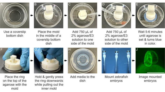
Figure 2: Using a 3D-printed mold to make agarose wells in a coverslip bottom dish. (A) Use a 30 mm coverslip bottom dish. (B) Place the SLA 3D-printed mold in the center of the coverslip bottom dish. (C) Slowly release 750 µL of molten 2% agarose/E3 around the right half of the mold perimeter. (D) Repeat Step C for the left half of the mold perimeter, evenly distributing a total of 1.5 mL of molten 2% agarose/E3 around the entire perimeter of the mold. (E) Wait 5-6 min for the agarose to solidify (it turns slightly blue in color). (F) Place the 3D-printed outer ring directly over the top of the inner mold and solidified agarose with the arrow pointing down. Before adding media, a layer of molten agarose can be added around the dish so that it slightly overlaps the central solidified agarose. This enhances the stability and attachment of the agarose wells to the dish. (G) Remove the inner mold from the solidified agarose by gently pushing down on the outer ring while using the handle to simultaneously gently pull directly up on the inner mold. Be careful not to damage the agarose wells by twisting or shifting the mold as you pull up. Wait for this extra-agarose to solidify. (H) Add enough media to the dish to cover the agarose wells. (I) Embryos are then mounted and properly oriented in the agarose wells using a pipette and forceps. (J) A representative image of a 96 hpf heart containing the Tg(myl7:egfp) transgene is shown. Scale bar = 100 µm (J). Please click here to view a larger version of this figure.
Supplemental Figure S1: 3D-printed accessories for the mounting of zebrafish embryos. (A) A screening mold for high-throughput screening of zebrafish embryos using an upright microscope. Left section of panel - design schematic, middle section of panel - cartoon showing orientation of zebrafish embryo in an individual well, right section of panel - picture of embryo in an individual well. Scale = 100 µm. (B) The outer ring is used in conjunction with the 3D-printed inner molds (see Figure 2) to facilitate the removal of the inner mold from the agarose wells. Left section of panel - design schematic, right section of panel - photo of outer ring and a mold prior to removal of the mold from the agarose wells. (C) Coverslip holder to facilitate the imaging of embryos mounted using the traditional technique of placing an embryo between two coverslips. Left section of panel - design schematic, right section of panel - photo of slide holder in which layers of vinyl tape placed on a large coverslip provide a window for mounting an embryo and for preventing crushing when placing a smaller coverslip on top. Please click here to download this File.
Supplemental Figure S2: A tilting motion for creating agarose wells with the screening mold. Cartoon of the tilting motion needed to create agarose wells with the screening mold. Placing one side of the screening mold down and then gradually placing the rest of the mold into the petri dish prevents the introduction of bubbles. Please click here to download this File.
Supplemental Figure S3: In vivo time series of cardiac development performed using agarose wells made with the HW mold. (A) Brightfield images of four 60 hpf zebrafish embryos mounted in agarose wells created by the HW mold. (B-E′′′) Embryos were kept in the wells for 12 h, and the hearts from individual embryos (B = E1, C = E2, D = E3, E = E4) were imaged every 4 h. The cardiac morphology of each embryo was imaged at (B-E) 60 hpf, (B′-E′) 64 hpf, (B′′-E′′) 68 hpf, and (B′′′-E′′′) 72 hpf. Embryos were incubated for an additional 24 h after imaging. All four embryos appeared viable and healthy. Scale bars = 100 μm. Please click here to download this File.
Supplemental Figure S4: A list of molds designed to orient zebrafish embryos for imaging cardiac development and for imaging along the dorsal, lateral or ventral axes. Header for each panel contains mold name, appropriate developmental stage of embryos to use with this mold, orientation of the embryos, and appropriate type of microscope (upright or inverted) to use for imaging. Left section of panels - design schematic, Middle section of panels - cartoon showing orientation of zebrafish embryo when mounted in an agarose well created by the mold. Yellow disc indicates location of the microscope objective. Right section of panels - picture of a zebrafish embryo mounted in an agarose well created by the mold. (A) Mold #A - All: this mold is designed for imaging early stages of zebrafish development (0-10 hpf), including cardiac specification using both inverted and upright microscopes. (B) Mold #CF - Cardiac fusion: this mold is designed for imaging cardiac fusion (12-22 hpf) with an inverted microscope. (C) Mold #LF - Lumen Formation: this mold is designed for imaging lumen formation and heart tube elongation (19-36 hpf) with an inverted microscope. (D) Mold #V2 - Ventral 2: this mold is designed for imaging later cardiac developmental events such as chamber formation and cardiac maturation (36-96 hpf) with an inverted microscope. (E) Mold #ST - Standing: this mold is designed for imaging the early stages of cardiac development (14-28 hpf) using an upright microscope. (F) Mold #HW - Halfway: this mold is designed for imaging later cardiac developmental events with an upright microscope. (G) Mold #D - Dorsal: this mold is designed for imaging the dorsal side of zebrafish embryos, including the dorsal regions of the brain. (H) Mold #L - Lateral: this mold is designed for imaging the lateral regions of the zebrafish embryo, including the trunk. (I) Mold #V1 - Ventral 1: this mold is designed for imaging the ventral side of zebrafish embryos. Please click here to download this File.
Supplemental Video S1: A representative time-lapse video of intersomitic vessel formation. ISV formation was captured by using the L mold to create agarose wells in which Tg(fli1a:egfp) zebrafish embryos are mounted in a lateral position. Time-lapse videos were created from three-dimensional reconstructions of confocal slices taken at 2:56 min intervals for ~3.5 h, beginning at 24 hpf. Scale = 10 µm. Arrows indicate the position of endothelial protrusions. Abbreviation: ISV = intersomitic vessel. Please click here to download this File.
Supplemental File 1: STL files of mold bases for inverted and upright microscopes to which pegs can be added and different pegs designs that can be further customized. Please click here to download this File.
Supplemental File 2: STL files of predesigned molds that can be printed or modified. Please click here to download this File.
Supplemental File 3: Tips for designing and creating custom molds for mounting zebrafish embryos. Please click here to download this File.
Discussion
Loading...
$$\rightleftharpoonup{xx}$$
$$\longleftharp{xx}$$,
$$\longrightharp{xx}$$,
In this protocol, we outline a method for designing 3D-printed molds that create agarose wells which can facilitate the mounting of embryos or tissues for imaging studies. These molds can be made for imaging with either upright or inverted microscopes and the agarose wells made by using these custom molds can be used for imaging applications that range from immunofluorescence studies of fixed embryos to timelapse imaging of live embryos.
This method utilizes a foundation that contains two pieces: an inner plunger-shaped base mold with pegs attached and an outer ring. We have incorporated several key design features into these molds. The most significant of these features are the pegs located at the bottom of the inner mold. The shape of these pegs can be customized to create differently shaped agarose wells, which help to orient embryos in a reproducible manner for imaging. Additional design features include an impression of the mold name at one end of the agarose wells, creating an asymmetry that allows each well to be uniquely identified. Divots were added around the base of the inner mold to facilitate the innervation of molten agarose around the pegs. Molten agarose should be non-viscous and clear but cool enough to pipet without creating bubbles. Furthermore, while having pegs bottom-out at the coverslip is advantageous for inverted microscopes since it allows embryos to be placed as close to the coverslip as possible, this is not helpful for upright microscopes. Thus, for upright microscopes, we created a separate inner mold with a lip around the bottom edge that prevents the pegs from sinking all the way to the bottom (for an example, see Figure 1E). Finally, an outer ring placed over the inner mold after the agarose has solidified ensures that the agarose wells stay stuck to the imaging dish and that they aren't damaged when the inner mold is removed.
Building on this foundation, we designed and tested molds for imaging cardiac development and for general zebrafish imaging. The molds for imaging cardiac development include 4 molds designed to be used with an inverted microscope-All (A), Cardiac fusion (CF), Lumen formation (LF), and Ventral 2 (V2); and two molds to be used with an upright microscope-Standing (ST) and Halfway (HW). The All mold creates a well for imaging cardiac specification from 0 to 10 hpf (Supplemental Figure S4A). The CF mold helps embryos balance upside down so that the process of cardiac fusion can be imaged from the dorsal side (Supplemental Figure S4B). A steep gradient on one wall of the agarose well is created with the LF mold, allowing lumen formation, which occurs under the head and on the side of the embryo, to be imaged (Supplemental Figure S4C). For the V2 mold, a slope is created by the mold so that the head is tilted forward over the yolk, placing the heart, which is on the ventral side of the embryo starting at 36 hpf, perpendicular to the coverslip (Supplemental Figure S4D). For imaging with an upright microscope such as a stereo microscope, the ST mold creates slender agarose wells in which to place the trunk. This stably positions the dorsal side of the embryo up towards an upright objective allowing heart development to be visualized from 14 hpf to 28 hpf (Supplemental Figure S4E). To image cardiac development on an upright microscope when the heart is on the ventral side of the embryo, a mold that creates shallow agarose wells with a gradual incline was created (Supplemental Figure S4F). Molds for mounting zebrafish embryos for inverted microscopes along the major axes: dorsal (Supplemental Figure S4G), lateral (Supplemental Figure S4H), and ventral (Supplemental Figure S4I) were also created. For routine transgenic and mutant screening of zebrafish embryos with a fluorescent stereo microscope, we designed a large mold that creates 120 shallow agarose wells in which 24-72 hpf embryos can fit (Supplemental Figure S1A). This mold is designed for a 100 mm diameter dish. An inexpensive coverslip holder for traditional mounting using two coverslips was also designed. This coverslip holder fits most microscope stages and helps in the movement of embryos to and from the microscope (Supplemental Figure S1C).
An important consideration in our design process is the resolution, accuracy, and precision of the 3D printer. Several factors affect the accuracy and repeatability of creating wells of the intended shape and size, including printer resolution, resin material, and resin shrinkage over time, as well as type and percentage of agarose used34. The reported resolution of the SLA Mars 2 Pro printer is 0.05 mm along the XY axis, with a Z axis accuracy of 0.00125 mm35. Additionally, we observed that agarose wells designed with an intended length of 4.30 mm, measured between 4.24 mm and 4.34 mm, with an average of 4.29 mm (n = 5), which indicates a 0.04-0.06 mm or 0.93-1.4% variation. To account for variation in the size of embryos, several embryos are also measured. We then ensured that our designs were tolerant to both the variation in embryo size and in agarose well size. When embryos are not held snuggly in the agarose wells, due to these variations, we add low-melting temperature agarose or methylcellulose to help keep them in place. Since agarose is quite pliable, if an agarose well is a little tight, the walls can be pushed apart to insert an embryo.
The downside of using inexpensive hobbyist 3D printers, such as those used here, is a decrease in accuracy and precision. Thus, if a high-resolution agarose well with low tolerance for variation is required, several printings may be required or a different printer may be needed. (For an FDM printer, such as the one used for the coverslip holder, resolution is determined by nozzle size. However, as the coverslip simply sits on top of the coverslip holder lip, a high amount of accuracy is not required for this design.)
As we have optimized the procedure using these molds to create agarose wells, we have identified several key steps and tips for their successful design and use (see Supplemental File 3). For example, after the molds have been manufactured, it is important to cure them with UV light, this can be done with a commercially available device (e.g., Elegoo Mercury v3.0) or by leaving the molds under a tissue culture hood with the UV light turned on. Additionally, it is important to verify that the 2% agarose solution is completely molten when adding it to the mold on the coverslip-bottom dish and that the right amount is added. If too much molten agarose is added the mold becomes difficult to extract from the solidified agarose. However, holes can appear in the agarose when too little molten agarose is added. When imaging on an inverted microscope it was often necessary to use forceps to peel a thin layer of agarose off the bottom of the well, this allows the embryo to get as close to the coverslip as possible. Finally, although these agarose wells were often sufficient to hold embryos in the right orientation for imaging, we occasionally found it necessary to also use low-melting temperature agarose in conjunction with the agarose wells, especially if specimen drift is a problem during a long imaging session. However, high concentrations of low-melting temperature agarose have been shown to cause developmental malformations and reduce embryo viability4. In our experience6,36, agarose wells themselves have little to no effect on embryo viability and developmental malformations, nor do they affect image quality, including photo-bleaching and the signal-to-noise ratio. However, concentration and age of tricaine, concentration of low-melting temperature agarose, and photo-toxicity are the biggest factors in embryo health and viability during live-imaging, as has been previously reported2,4. The agarose wells also do not affect downstream sample processing, including genotyping. Indeed, we routinely remove embryos from the agarose wells after imaging and allow them to continue to develop for 24 h to ensure viability during the imaging process.
By standardizing agarose well formation and creating different well shapes for different imaging orientations, this work expands upon our previous work6 in which agarose wells were created by hand to facilitate live imaging. Furthermore, we hope our work here builds upon the previously created imaging molds8,12,17,19 by increasing the accessibility and ease of use for researchers. That is why, along with a protocol for utilizing 3D printed molds to mount zebrafish embryos, we also present a design framework that allows researchers to take advantage of inexpensive SLA and FDM 3D-printers to create their own customized molds. We have created predesigned molds ready for use in imaging zebrafish cardiac development and for general zebrafish imaging, including for screening embryos. Unlike several of the previously reported 3D-printed approaches in which embryos are mounted in silicone, PDMS, or polystyrene wells12,17,19, our method uses resin-based molds to create agarose wells, which is a relatively gentle structural environment and is readily accessible in research laboratories. However, our agarose wells do not facilitate microfluidic or experimental approaches that seek to isolate the environment of individual embryos during imaging16,17.
It is our hope that the accessibility of 3D-printers and ability to easily tailor the design of molds based on the specific imaging challenge without starting from scratch democratizes the ability of researchers to create customized mounting instruments for their imaging challenges. We hope that our predesigned molds will be useful to the zebrafish cardiac developmental biology community and the zebrafish community more generally. In the future, these designs could be easily customized for different tissues at progressive developmental stages; for example, one could design molds for imaging zebrafish brain development or spinal cord regeneration. Additionally, we expect these molds could be customized for imaging other model or non-model organisms such as mouse, Xenopus, Cavefish, and Killifish, as well as perhaps for the creation and imaging of organoids.
Disclosures
Loading...
$$\rightleftharpoonup{xx}$$
$$\longleftharp{xx}$$,
$$\longrightharp{xx}$$,
The authors have no conflicts of interest to declare.
Acknowledgements
Loading...
$$\rightleftharpoonup{xx}$$
$$\longleftharp{xx}$$,
$$\longrightharp{xx}$$,
We would like to thank members of the Bloomekatz laboratory, especially Sasmitha Singh and Allison Holmes, as well as the GlyCORE imaging core (supported by P20GM130460), the University of Mississippi IDEA lab, Dr. Yiwei Han and the Han laboratory, and members of the University of Mississippi Glycoscience and Developmental Biology communities. This work is supported by funding from the NIH (R15HD108782, P20GM130460).
Materials
| Name | Company | Catalog Number | Comments |
|---|---|---|---|
| SLA 3D Printer | Elegoo | MARS 2 PRO | |
| Agarose | Apex Bioresearch; Genesee Scientific | 20-102QD | Any brand may be substituted |
| Autodesk Fusion 360 | Autodesk Inc. | https://www.autodesk.com/products/fusion-360/ | Computer aid design (CAD) Software - more advanced |
| Axio-Zoom upright microscope | Zeiss | Axio Zoom.V16 | |
| Chitubox | CBD-Tech | https://www.chitubox.com/ | Slicer software |
| Coverslip bottom dish (60 mm dish with 30 mm bottom well) | Cellvis | D60-30-1.5N | |
| F59 Myosin heavy chain (all fast isoforms) | DHSB | F59 | 1:50 dilution |
| FDM filaments | Bambu | PLA filaments | |
| FDM printer | Bambu | Bambu X1 Carbon FDM | 0.4mm extruder nozzle |
| Forceps | Fisher | 16-100-121 | Other brands are likely to be suitable |
| Goat anti-mouse Alexa 488 | ThermoFisher | #A28175 | 1:300 dilution |
| Imaris | Andor | 10.2 | Software |
| Inverted Confocal Microscope | Leica | Leica SP8 X | |
| Low-melt temperature agarose | Gold Biotechnology | Catalog No: A-204-25 | Other brands are likely to be suitable |
| Pipette pump | Bel-Art | F37898 | |
| Resin for SLA printer | Elegoo | Elegoo P05BB028 | Water washable photopolymer Resin V2.0 |
| Ricinus communis agglutinin (RCA-120) | Vector labs | #RLK-2200 (lectin kit) | 1:300 dilution |
| TinkerCAD | Autodesk Inc. | https://www.tinkercad.com/ | Computer aid design (CAD) Software - basic |
| Tricaine S | Western Chemical, Inc. | ANADA #200-226 | |
| Wheat germ agglutinin (WGA) | Vector labs | #RLK-2200 (lectin kit) | 1:300 dilution |
| Wide-bore glass Pasteur pipette | Duran Wheaton Kimble (DWK) | 63A53WT |
References
Loading...
$$\rightleftharpoonup{xx}$$
$$\longleftharp{xx}$$,
$$\longrightharp{xx}$$,
- Using zebrafish to analyze the genetic and environmental etiologies of congenital heart defects. Adv Exp Med Biol. 1236, 189-223 (2020).">Shrestha, R., Lieberth, J., Tillman, S., Natalizio, J., Bloomekatz, J. Using zebrafish to analyze the genetic and environmental etiologies of congenital heart defects. Adv Exp Med Biol. 1236, 189-223 (2020).
- The zebrafish book: a guide for the laboratory use of zebrafish (Danio rerio). , 5th edn, Univ. of Oregon Press. (2007).">Westerfield, M. The zebrafish book: a guide for the laboratory use of zebrafish (Danio rerio). , 5th edn, Univ. of Oregon Press. (2007).
- A layered mounting method for extended time-lapse confocal microscopy of whole zebrafish embryos. J Vis Exp. (155), e60321(2020).">Upadhyay, S., et al. A layered mounting method for extended time-lapse confocal microscopy of whole zebrafish embryos. J Vis Exp. (155), e60321(2020).
- Multilayer mounting enables long-term imaging of zebrafish development in a light sheet microscope. Development. 139 (17), 3242-3247 (2012).">Kaufmann, A., Mickoleit, M., Weber, M., Huisken, J. Multilayer mounting enables long-term imaging of zebrafish development in a light sheet microscope. Development. 139 (17), 3242-3247 (2012).
- Confocal microscopic analysis of morphogenetic movements. Methods Cell Biol. 59, 179-204 (1999).">Cooper, M. S., D'Amico, L. A., Henry, C. A. Confocal microscopic analysis of morphogenetic movements. Methods Cell Biol. 59, 179-204 (1999).
- Using live imaging to examine early cardiac development in zebrafish. Methods Mol Biol. 2438, 133-145 (2022).">McCann, T., Shrestha, R., Graham, A., Bloomekatz, J. Using live imaging to examine early cardiac development in zebrafish. Methods Mol Biol. 2438, 133-145 (2022).
- A versatile mounting method for long term imaging of zebrafish development. J Vis Exp. (119), e55210(2017).">Hirsinger, E., Steventon, B. A versatile mounting method for long term imaging of zebrafish development. J Vis Exp. (119), e55210(2017).
- Standardized mounting method of zebrafish embryos using a 3D-printed stamp for high-content, semi-automated confocal imaging. BMC Biotechnol. 19 (1), 68(2019).">Kleinhans, D. S., Lecaudey, V. Standardized mounting method of zebrafish embryos using a 3D-printed stamp for high-content, semi-automated confocal imaging. BMC Biotechnol. 19 (1), 68(2019).
- All-in-one 3D printed microscopy chamber for multidimensional imaging, the universlide. Sci Rep. 7, 42378(2017).">Alessandri, K., et al. All-in-one 3D printed microscopy chamber for multidimensional imaging, the universlide. Sci Rep. 7, 42378(2017).
- In toto imaging of embryogenesis with confocal time-lapse microscopy. Methods Mol Biol. 546, 317-332 (2009).">Megason, S. G. In toto imaging of embryogenesis with confocal time-lapse microscopy. Methods Mol Biol. 546, 317-332 (2009).
- Live imaging of the cytoskeleton in early cleavage-stage zebrafish embryos. Methods Cell Biol. 101, 1-18 (2011).">Wühr, M., Obholzer, N. D., Megason, S. G., Detrich, H. W. III, Mitchison, T. J. Live imaging of the cytoskeleton in early cleavage-stage zebrafish embryos. Methods Cell Biol. 101, 1-18 (2011).
- Low-cost silicone imaging casts for zebrafish embryos and larvae. Zebrafish. 11 (1), 26-31 (2013).">Masselink, W., Wong, J. C., Liu, B., Fu, J., Currie, P. D. Low-cost silicone imaging casts for zebrafish embryos and larvae. Zebrafish. 11 (1), 26-31 (2013).
- Generation of orientation tools for automated zebrafish screening assays using desktop 3D printing. BMC Biotechnol. 14, 36(2014).">Wittbrodt, J. N., Liebel, U., Gehrig, J. Generation of orientation tools for automated zebrafish screening assays using desktop 3D printing. BMC Biotechnol. 14, 36(2014).
- A bioelectrical phase transition patterns the first vertebrate heartbeats. Nature. 622 (7981), 149-155 (2023).">Jia, B. Z., Qi, Y., Wong-Campos, J. D., Megason, S. G., Cohen, A. E. A bioelectrical phase transition patterns the first vertebrate heartbeats. Nature. 622 (7981), 149-155 (2023).
- Microstructured devices for optimized microinjection and imaging of zebrafish larvae. J Vis Exp. 130, e56498(2017).">Ellett, F., Irimia, D. Microstructured devices for optimized microinjection and imaging of zebrafish larvae. J Vis Exp. 130, e56498(2017).
- Low-cost polyethylene terephthalate lamination microfluidics designs for multiplexed zebrafish imaging. J Vis Exp. (211), e67313(2024).">Tan, S., Zhu, X., Zartman, J. J., Deng, Q. Low-cost polyethylene terephthalate lamination microfluidics designs for multiplexed zebrafish imaging. J Vis Exp. (211), e67313(2024).
- Zebrafish entrapment by restriction array (ZEBRA) device: a low-cost, agarose-free zebrafish mounting technique for automated imaging. Lab Chip. 13 (9), 1732-1736 (2013).">Bischel, L. L., Mader, B. R., Green, J. M., Huttenlocher, A., Beebe, D. J. Zebrafish entrapment by restriction array (ZEBRA) device: a low-cost, agarose-free zebrafish mounting technique for automated imaging. Lab Chip. 13 (9), 1732-1736 (2013).
- Automated feature detection and imaging for high-resolution screening of zebrafish embryos. Biotechniques. 50 (5), 319-324 (2011).">Peravali, R., et al. Automated feature detection and imaging for high-resolution screening of zebrafish embryos. Biotechniques. 50 (5), 319-324 (2011).
- A four-well dish for high-resolution longitudinal imaging of the tail and posterior trunk of larval zebrafish. Zebrafish. 14 (5), 489-491 (2017).">Weijts, B., Tkachenko, E., Traver, D., Groisman, A. A four-well dish for high-resolution longitudinal imaging of the tail and posterior trunk of larval zebrafish. Zebrafish. 14 (5), 489-491 (2017).
- 3D printing technology; methods, biomedical applications, future opportunities and trends. J Mater Res Technol. 14, 1430-1450 (2021).">Bozkurt, Y., Karayel, E. 3D printing technology; methods, biomedical applications, future opportunities and trends. J Mater Res Technol. 14, 1430-1450 (2021).
- Frontiers of 3D printing/additive manufacturing: from human organs to aircraft fabrication. J Mater Sci Technol. 32 (10), 987-995 (2016).">Murr, L. E. Frontiers of 3D printing/additive manufacturing: from human organs to aircraft fabrication. J Mater Sci Technol. 32 (10), 987-995 (2016).
- Development of 3D bioprinting: from printing methods to biomedical applications. Asian J Pharm Sci. 15 (5), 529-557 (2020).">Gu, Z., Fu, J., Lin, H., He, Y. Development of 3D bioprinting: from printing methods to biomedical applications. Asian J Pharm Sci. 15 (5), 529-557 (2020).
- Fiji: an open-source platform for biological-image analysis. Nat Methods. 9 (7), 676-682 (2012).">Schindelin, J., et al. Fiji: an open-source platform for biological-image analysis. Nat Methods. 9 (7), 676-682 (2012).
- Dissection and lateral mounting of zebrafish embryos: analysis of spinal cord development. J Vis Exp. (84), e50703(2014).">Beck, A. P., Watt, R. M., Bonner, J. Dissection and lateral mounting of zebrafish embryos: analysis of spinal cord development. J Vis Exp. (84), e50703(2014).
- Germ-line transmission of a myocardium-specific GFP transgene reveals critical regulatory elements in the cardiac myosin light chain 2 promoter of zebrafish. Dev Dyn. 228 (1), 30-40 (2003).">Huang, C. J., Tu, C. T., Hsiao, C. D., Hsieh, F. J., Tsai, H. J. Germ-line transmission of a myocardium-specific GFP transgene reveals critical regulatory elements in the cardiac myosin light chain 2 promoter of zebrafish. Dev Dyn. 228 (1), 30-40 (2003).
- Platelet-derived growth factor (PDGF) signaling directs cardiomyocyte movement toward the midline during heart tube assembly. eLife. 6, (2017).">Bloomekatz, J., et al. Platelet-derived growth factor (PDGF) signaling directs cardiomyocyte movement toward the midline during heart tube assembly. eLife. 6, (2017).
- Essentials of Glycobiology. Varki, A., et al. Ch 48, Cold Spring Harbor Laboratory Press, Cold Spring Harbor, NY. 645-661 (2022).">Cummings, R. D., et al. Essentials of Glycobiology. Varki, A., et al. Ch 48, Cold Spring Harbor Laboratory Press, Cold Spring Harbor, NY. 645-661 (2022).
- Identification of two binding sites for wheat-germ agglutinin on polylactosamine-type oligosaccharides. Biochem J. 231 (1), 115-122 (1985).">Gallagher, J. T., Morris, A., Dexter, T. M. Identification of two binding sites for wheat-germ agglutinin on polylactosamine-type oligosaccharides. Biochem J. 231 (1), 115-122 (1985).
- Structural requirements for the binding of oligosaccharides and glycopeptides to immobilized wheat germ agglutinin. Biochemistry. 20 (20), 5894-5899 (1981).">Yamamoto, K., Tsuji, T., Matsumoto, I., Osawa, T. Structural requirements for the binding of oligosaccharides and glycopeptides to immobilized wheat germ agglutinin. Biochemistry. 20 (20), 5894-5899 (1981).
- Crystallographic refinement and structure analysis of the complex of wheat germ agglutinin with a bivalent sialoglycopeptide from glycophorin A. J Mol Biol. 232 (2), 620-638 (1993).">Wright, C. S., Jaeger, J. Crystallographic refinement and structure analysis of the complex of wheat germ agglutinin with a bivalent sialoglycopeptide from glycophorin A. J Mol Biol. 232 (2), 620-638 (1993).
- In vivo imaging of embryonic vascular development using transgenic zebrafish. Dev Biol. 248 (2), 307-318 (2002).">Lawson, N. D., Weinstein, B. M. In vivo imaging of embryonic vascular development using transgenic zebrafish. Dev Biol. 248 (2), 307-318 (2002).
- Angiogenic network formation in the developing vertebrate trunk. Development. 130 (21), 5281-5290 (2003).">Isogai, S., Lawson, N. D., Torrealday, S., Horiguchi, M., Weinstein, B. M. Angiogenic network formation in the developing vertebrate trunk. Development. 130 (21), 5281-5290 (2003).
- Translating imaging into 3D printed cardiovascular phantoms: a systematic review of applications, technologies, and validation. JACC Basic Transl Sci. 7 (10), 1050-1062 (2022).">Illi, J., et al. Translating imaging into 3D printed cardiovascular phantoms: a systematic review of applications, technologies, and validation. JACC Basic Transl Sci. 7 (10), 1050-1062 (2022).
- Measuring and establishing the accuracy and reproducibility of 3D printed medical models. Radiographics. 37 (5), 1424-1450 (2017).">George, E., Liacouras, P., Rybicki, F. J., Mitsouras, D. Measuring and establishing the accuracy and reproducibility of 3D printed medical models. Radiographics. 37 (5), 1424-1450 (2017).
- https://us.elegoo.com/products/elegoo-mars-2-pro-mono-lcd-3d-printer (2025).">Elegoo Mars 2 Pro Mono LCD 3D Printer. , https://us.elegoo.com/products/elegoo-mars-2-pro-mono-lcd-3d-printer (2025).
- The myocardium utilizes a platelet-derived growth factor receptor α (PDGFRα)-phosphoinositide 3-kinase (PI3K) signaling cascade to steer toward the midline during zebrafish heart tube formation. ELife. 12, e85930(2023).">Shrestha, R., et al. The myocardium utilizes a platelet-derived growth factor receptor α (PDGFRα)-phosphoinositide 3-kinase (PI3K) signaling cascade to steer toward the midline during zebrafish heart tube formation. ELife. 12, e85930(2023).
Reprints and Permissions
Request permission to reuse the text or figures of this JoVE article
Request Permission