本文介绍一种用于重现器官水平功能的可拉伸双通道器官芯片微流控细胞培养装置的制备方案 体外.
需要JoVE订阅才能观看此内容。 请登录或开始免费试用
本文内容
勘误通知
Important: There has been an erratum issued for this article. View Erratum Notice
摘要
摘要
大量先导化合物在药物研发管线中失败,原因是动物研究通常无法准确预测人类患者的临床反应。人体器官芯片(Organ Chip)微流控细胞培养装置提供了一种实验方法 体外 用于评估人体内的疗效、毒性和药代动力学(PK)特征的平台,可能比动物实验更能准确预测临床治疗效果与安全性。这些装置可模拟几乎所有器官类型的功能,并可通过共用的内皮细胞衬覆微通道进行流体连接,以实现 体外 无需在人体上进行实验即可开展人体器官层面及整体生理学研究。这些器官芯片由两条灌注式微流控通道组成,通道之间由可渗透的弹性膜隔开,膜的一侧接种有器官特异性的实质细胞,另一侧为微血管内皮细胞,该膜可周期性拉伸以提供器官特异性的机械刺激例如, 肺部呼吸运动)。本方案详细介绍了利用3D打印模具通过铸造法制造柔性双通道器官芯片的方法,可实现多种铸造及后续加工步骤的整合。采用在压力作用下使用硅柱阵列的方法,可铸造出具有微米级通孔的多孔聚二甲基硅氧烷(PDMS)膜。器官芯片的制备与组装所涉及的设备和步骤均可在传统洁净室之外实施。本方案使研究人员能够便捷地获取器官芯片技术,用于 体外 药物发现、安全性和有效性测试,以及基本生物过程的机制研究中的器官和整体水平研究。
引言
在此,我们介绍一种可规模化制备双通道、血管化器官芯片微流体培养装置的方法。该方案适用于无法使用洁净室和传统软光刻工具的研究团队。这些装置旨在重现人体器官水平的功能,以研究正常与疾病生理学以及药物反应。 体外1,2. 实现这一功能的关键在于由半透膜分隔的两个灌注微流控通道(图1这种设计能够重建至少两种组织之间的组织-组织界面,通常在多孔膜的一侧培养器官实质细胞,另一侧培养血管内皮层,同时可使这些细胞暴露于流体流动环境中。此外,由于采用弹性聚合物聚二甲基硅氧烷(PDMS)制造器官芯片的主体和膜组件,因而可对整个工程化的组织-组织界面施加周期性机械应变。 通过 弹性膜以模拟活体器官的天然物理微环境,例如肺部的呼吸运动和肠道的蠕动。
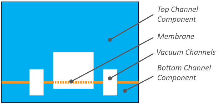
图1:器官芯片横截面。 器官芯片由两个通道组成,中间由多孔弹性膜隔开,膜的两侧均可接种细胞。上通道横截面为1 ....
访问受限。请登录或开始试用以查看此内容。
方案
1. 常规准备
- 为避免碎屑污染,使用封箱胶带清洁工作区域,并用洁净室擦拭布和异丙醇擦拭表面。
- 所有涉及聚二甲基硅氧烷(PDMS)的操作步骤中,按10:1的比例混合PDMS(10 g交联剂,100 g弹性体基质)。可手动混合或使用商用混合器。此处使用行星式离心混合器:在2000 rpm条件下混合2分钟,随后在2200 rpm条件下脱气2分钟。
- 使用前,用气枪吹净所有模具以去除碎屑。
注意:切勿使用金属镊子清除碎屑,以免损坏模具表面。
2. 上层通道制备
- 用乙醇和无尘布擦拭每块聚氨酯的光面。确保聚氨酯表面残留的乙醇完全干燥。
- 将聚氨酯的光面覆盖在MiP模具的开口端,以密封模具的开口侧,仅在模具顶部留出一个类似孔洞的开口用于倒入PDMS。
注意:请检查每个模具是否均被聚氨酯片牢固覆盖,否则在倒入PDMS时会发生泄漏。 - 将模具与聚氨酯组件放入MiP夹具中,使模具的纹理面紧贴夹具末端。重复此操作,直至所有模具均放入夹具。
- 使用扳手旋转手柄,拧紧MiP夹具,直至夹具间距为25 mm宽。
- 用铝箔围绕MiP夹具制作一个“船形”围挡,防止多余的PDMS溢出到台面上。
- 将PDMS倒入每个模具的孔洞中,直至充满。
注意:每个....
访问受限。请登录或开始试用以查看此内容。
结果
本文所述方案介绍了一种可扩展的PDMS器官芯片的制备方法。该装置可在弹性多孔膜上实现两种不同灌注组织类型的培养(图1)。PDMS 通道使用 3D 打印模具进行浇铸,可加快新设计的原型制作(图 2A 以及 2B)。上层通道在模具中通过压缩柔性聚氨酯垫圈铸造,以制备带有模压接口的部件(图 2C)而底部通道组件则在托盘中浇铸,并以显微镜载玻片作为基底进行操作(图 2D)。这种制备方法将各部件的多尺度图案化整合到一步完成,节省了时间,提高了可重复性和可追溯性,并减少了因打孔和多次切割产生的碎屑。多孔膜对于器官芯片的功能至关重要,而采用在图案化硅片上浇铸成型的制备方法可获得厚度一致、表面光洁度良好的膜结构。图3)。操作 通过 .......
访问受限。请登录或开始试用以查看此内容。
讨论
该制造工艺依赖高分辨率3D打印模具,用于成型PDMS上层和下层器官芯片主体部件,并结合微模压多孔PDMS膜。选择这一关键技术方案,是因为其原型制作简便,且可快速过渡到规模化生产并实现工装的更换。上层部件的模具设计可在浇铸过程中,在精确位置形成具有特定垂直轮廓的接口端口。这不仅避免了手动打孔接入端口所需的劳动,还减少了工作场所的碎屑,实现了端口与流体分配装置或仪器接口的可重复对准,并使插入的导管或插针在流体和气动连接中的配合与密封具有可控性。模具通过弹性聚氨酯片分隔后逐层堆叠于压缩夹具中,以实现端口的通孔浇铸。通过在单个夹具中堆叠多个部件,单个操作者即可在一步操作中批量浇铸出带端口的大量组件。模具的材料选择与制造方法至关重要,需提供必要的特征分辨率、低表面粗糙度以及高平整度,以满足器件组装及后续成像应用的要求。立体光刻(Stereolithography)能够满足这些要求,但需选用具有高挠曲温度(> 80 °C)且与PDMS固化兼容的材料,这限制了可用聚合物的范围。目前市场上多种可选树脂(包括含玻璃填料的树脂)均能满足这些标准。
弹性多孔PDMS膜可以说是器官芯片中最独特且最关键的组.......
访问受限。请登录或开始试用以查看此内容。
披露
D.E.I. 是 Emulate 公司的创始人并持有该公司股权,同时担任其科学顾问委员会主席。J.P. 目前是 Emulate 公司的员工。R.N.、Y.C.、J.P. 和 D.E.I. 均为已授权给 Emulate 公司的知识产权的发明人。
致谢
感谢 M. Rousseau 和 S. Kroll 在摄影与摄像方面的协助,感谢 M. Ingram、J. Nguyen、D. Shea 和 N. Wen 对初始制造方案开发的贡献。本研究由哈佛大学威斯生物启发工程研究所、美国国防高级研究计划局(合作协定编号 #W911NF-12-2-0036 和 #W911NF-16-C-0050)、美国食品药品监督管理局(FDA 资助编号 #HHSF223201310079C)、美国国立卫生研究院(NIH 资助编号 #R01-EB020004 和 #UG3-HL141797-01)以及比尔及梅琳达·盖茨基金会(资助编号 #OPP1163237 和 #OPP1173198)资助。本文所表达的观点和结论仅代表作者立场,不应被视为代表美国国防高级研究计划局、食品药品监督管理局、国立卫生研究院或美国政府的官方政策,无论明示或暗示。
....访问受限。请登录或开始试用以查看此内容。
材料
| 姓名 | 公司 | 目录编号 | 评论 |
|---|---|---|---|
| 个人防护装备 | |||
| 发网 | VWR | 89107-770 | |
| 杜邦特卫强实验服 | VWR | 13450-506 | |
| 加长袖口手套 | VWR | 89521-898 | |
| 仪器设备 | |||
| 切割垫 | VWR | 102096-430 | |
| 瓷砖切割机 | McMaster-Carr | 26765A31 | |
| 原位成型(MIP)上模 | Protolabs, Inc. | 定制 | 使用 Prototherm 12120 打印 |
| 原位成型(MIP)底模 | Protolabs, Inc. | 定制 | 使用 Prototherm 12121 打印 |
| 鸭嘴形弯头镊子 | VWR | 63041-864 | |
| 尖头镊子 | 电子显微镜科学公司 | 72700-D | |
| 金属刮勺 | VWR | 82027-528 | |
| 深反应离子刻蚀(DRIE) 柱阵列晶圆 | Sensera, Inc. | 定制 | 每片晶圆包含四个 50 × 50 mm 的柱状阵列;柱体宽 7 μm,高 50 μm,呈六边形排列,间距 40 μm |
| 带纹理的聚碳酸酯 .01” 厚 | McMaster-Carr | 85585K33 | 切成45毫米见方 |
| PDMS 块(40 × 40 × 5 mm) | n/a | 定制 | |
| 层流罩 | 无菌 | BVBI | 自行制备 |
| 气枪 | |||
| 60°C级烘箱 | |||
| 真空干燥器 | |||
| 质量平衡 | 精确至0.1 g | ||
| 等离子体机器 | 迪纳 | 纳米 | 氧气等离子体功能至关重要 |
| 材料与试剂 | |||
| Sylgard 184 聚二甲基硅氧烷(PDMS)基础剂/固化剂套装 | 埃尔斯沃思粘合剂 | 4019862 | |
| 混合杯 | 处理预聚物时应确保充分通风,因其含有微量乙苯 | ||
| 1 mL 注射器 | VWR | 10099-395 | |
| 洁净室擦拭布 | VWR | TWTX1080 | |
| 25 x 75 mm 玻璃载玻片 | VWR | 48311-703 | |
| 封口胶带 | VWR | 500043-724 | |
| 透明胶带 | VWR | 500026-873 | |
| 模切聚氨酯(PU)条 | 大西洋垫圈公司 | custom: AGWI2X3 | 1/8” 厚型;60 邵氏硬度黑色聚氨酯;2” x 3” |
| 聚碳酸酯膜,0.005” 厚 | McMaster-Carr | 85585K102 | |
| 100 x 100 x 15 mm 方格培养皿 | VWR | 60872-480 | |
| 铝箔 | |||
| 可选设备 | |||
| Thinky PDMS 混合器 | Thinky | ARE-310 | |
| 原位成型(MIP)夹具 | 内部 | 螺钉夹紧压缩夹具 | |
| 自动膜制备仪(AMF) | 自主研发 | 可编程加热器气动压缩活塞阵列 |
参考文献
- Bhatia, S. N., Ingber, D. E. Microfluidic organs-on-chips. Nature Biotechnology. 32 (8), 760-772 (2014).
- Benam, K. H., et al. Engineered In vitro Disease Models. Annual Review of Pathology Mechanisms of Disease. 10 (1), 195-262 (2015).
- Huh, D., et al.
访问受限。请登录或开始试用以查看此内容。
重印与许可
勘误
Formal Correction: Erratum: Scalable Fabrication of Stretchable, Dual Channel, Microfluidic Organ Chips
Posted by JoVE Editors on 5/08/2019. Citeable Link.
An erratum was issued for: Scalable Fabrication of Stretchable, Dual Channel, Microfluidic Organ Chips. The Representative Results, Discussion, and References sections have been updated.
In the Representative Results section, the legend for Figure 5 has been updated from:
Figure 5: Permeability of inert tracer Cascade Blue through the microporous PDMS membrane. Cascade Blue hydrazide dye in medium was loaded into the top channel of the Organ Chip and perfused at 60 µL/h to measure the flux of the dye across the membrane into the bottom channel containing medium. Empty chips were compared to Gut Chips with Caco2-BBe1 cells in the apical channel and human vascular endothelial cells (HUVEC) in the basal channel cultured for 6 days. Error bars indicate standard error of the mean.
to:
Figure 5: Permeability of inert tracer Cascade Blue through the microporous PDMS membrane. Cascade Blue hydrazide dye in medium was loaded into the top channel of the Organ Chip and perfused at 60 µl/h to measure the flux of the dye across the membrane into the bottom channel containing medium. Empty chips were compared to Gut Chips with Caco2-BBe1 cells in the apical channel and human vascular endothelial cells (HUVEC) in the basal channel cultured for 6 days. The apparent permeability (Papp, cm/s) of the microporous PDMS membrane was determined using the dye concentration in the outlet channels. The gut chip cell layers provide a significantly increased barrier to permeability. Error bars indicate standard error of the mean.
In the Discussion section, the fourth paragraph has been updated from:
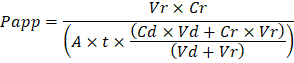
Troubleshooting the resulting Organ Chips takes place at two levels: during the fabrication process and during Organ Chip culture. We have developed a visual method for quality assurance (QA) of through-hole formation in the cast membranes that greatly accelerates the production process while improving the quality and reliability of assembled Organ Chips. This QA method allows for process troubleshooting, and we recommend keeping a record of process conditions to enable tracking fabrication problems that may occur during cell culture. During Organ Chip culture, inert tracer dyes are the simplest method of measuring barrier function to troubleshoot the fabrication process and cell culture steps. Lucifer Yellow has been used historically due to its small molecular mass and innate fluorescence, but Cascade Blue offers similar properties with a narrower emission spectrum that is less likely to interfere with downstream assays. Larger molecules, such as poly-ethyleneglycol (PEG)- or dextran-conjugated fluorophores are larger and consequently result in lower permeability overall and lower sensitivity. The apparent permeability (Papp, cm/s) of tracer dyes can be used to determine barrier function properties of organs or tissues (Figure 4). The following equation can be used to calculate Papp between the dosing channel and receiving channel and is derived from equations used primarily for Transwell studies19,20 and corrects for tracer dye loss caused by absorption into PDMS by comparing the two output flows and not relying on mass balance assumptions at the outflow.
to:
Troubleshooting the resulting Organ Chips takes place at two levels: during the fabrication process and during Organ Chip culture. We have developed a visual method for quality assurance (QA) of through-hole formation in the cast membranes that greatly accelerates the production process while improving the quality and reliability of assembled Organ Chips. This QA method allows for process troubleshooting, and we recommend keeping a record of process conditions to enable tracking fabrication problems that may occur during cell culture. During Organ Chip culture, inert tracer dyes are the simplest method of measuring barrier function to troubleshoot the fabrication process and cell culture steps. Lucifer Yellow has been used historically due to its small molecular mass and innate fluorescence, but Cascade Blue offers similar properties with a narrower emission spectrum that is less likely to interfere with downstream assays. Larger molecules, such as poly-ethyleneglycol (PEG)- or dextran-conjugated fluorophores are larger and consequently result in lower permeability overall and lower sensitivity. The apparent permeability (Papp, cm/s) of tracer dyes can be used to determine barrier function properties of organs or tissues (Figure 5). The following equation derived by Tran, et al.19 can be used to calculate Papp between the dosing channel and receiving channel, which partially corrects for tracer dye loss caused by absorption into PDMS by averaging the two output flows and not relying on mass balance assumptions at the outflow.

The References section has been updated from:
- Blaser, D.W. Determination of drug absorption parameters in Caco-2 cell monolayers with a mathematical model encompassing passive diffusion, carrier-mediated efflux, non-specific binding and phase II metabolism. at <http://edoc.unibas.ch/655/1/DissB_7998.pdf> (2007).
- Hubatsch, I., Ragnarsson, E.G.E., Artursson, P. Determination of drug permeability and prediction of drug absorption in Caco-2 monolayers. Nature Protocols. 2 (9), 2111-2119 (2007).
- Henry, O.Y.F. et al. Organs-on-chips with integrated electrodes for trans-epithelial electrical resistance (TEER) measurements of human epithelial barrier function. Lab on a Chip. 17 (13), 2264-2271 (2017).
- Maoz, B.M. et al. Organs-on-Chips with combined multi-electrode array and transepithelial electrical resistance measurement capabilities. Lab on a Chip. 17 (13), 2294-2302 (2017).
- Benam, K.H. et al. Matched-Comparative Modeling of Normal and Diseased Human Airway Responses Using a Microengineered Breathing Lung Chip. Cell Systems. 3 (5), 456-466.e4 (2016).
to:
- Tran, T.T. et al. Exact kinetic analysis of passive transport across a polarized confluent MDCK cell monolayer modeled as a single barrier. Journal of Pharmaceutical Sciences. 93 (8), 2108–2123 (2004).
- Henry, O.Y.F. et al. Organs-on-chips with integrated electrodes for trans-epithelial electrical resistance (TEER) measurements of human epithelial barrier function. Lab on a Chip. 17 (13), 2264-2271 (2017).
- Maoz, B.M. et al. Organs-on-Chips with combined multi-electrode array and transepithelial electrical resistance measurement capabilities. Lab on a Chip. 17 (13), 2294-2302 (2017).
- Benam, K.H. et al. Matched-Comparative Modeling of Normal and Diseased Human Airway Responses Using a Microengineered Breathing Lung Chip. Cell Systems. 3 (5), 456-466.e4 (2016).
