Ein Abonnement von JoVE ist erforderlich, um diesen Inhalt anzuzeigen. Melden Sie sich an oder beginnen Sie noch heute mit einer kostenlosen Testphase.

Methodenartikel

Simulating Fall-Induced Wrist Fractures Using a Cadaveric Human Forearm Specimen

239 Aufrufe

1. Juli 2026

In diesem Artikel

Zusammenfassung

Source:
Anthony J. Yosick1,2, Christine Massie1, Emma Knapp2, Hani A. Awad1,2,3

1Department of Biomedical Engineering, University of Rochester, US
2Center for Musculoskeletal Research, Department of Orthopedics, University of Rochester Medical Center, USA
3Department of Orthopedics, University of Rochester Medical Center, USA

The video demonstrates fall-related wrist fractures using human cadaver forearms with varying bone densities. Specimens are standardized by removing upper soft tissue, sectioning the bones, and positioning the forearm in pronation. The embedded forearm is loaded through the palm using a mechanical tester. Fracture is marked by a sudden drop in force, and the force–displacement curve is analyzed to assess bone strength and fracture resistance.
Protokoll

Disclaimer: All procedures involving sample collection have been performed in accordance with the institute's IRB guidelines.

Anonymized human cadaveric specimens were obtained through the Anatomy Gifts Registry (Hanover, MD).

1. Specimen preparation

1.1 Specimen thawing and dissection

  1. Collect fresh frozen forearm specimens disarticulated at the elbow from an anatomical donation registry. Store the specimens at -80 °C until testing is conducted.
  2. Thaw the specimens at room temperature (RT) for 18-20 h prior to beginning dissection and testing. Place the specimen on an absorbent pad to thaw.
  3. Following thawing, remove any packaging and absorbent pads from the specimen. Place the specimen on an absorbent pad for dissection. Dispose of all items that come into contact with the human cadaveric specimen appropriately in biohazard waste.
  4. Using a ruler and marker, measure and mark the location 3 inches proximal from the styloid process of the ulna. Dissect and remove all soft tissue proximal to this location.
  5. Using a scalpel, surgical scissors, and rat-tooth forceps, remove all soft tissue proximal to the marked location to expose the radius and ulna. Maintain all tissue and bone removed from the specimen in accordance with the requirements of the cadaveric registry company until properly disposed of.
  6. Using a ruler and marker, measure and mark the location 6 inches proximal from the styloid process of the ulna on the exposed radius and ulna. Dissect and remove the radius and ulna sections proximal to this location.
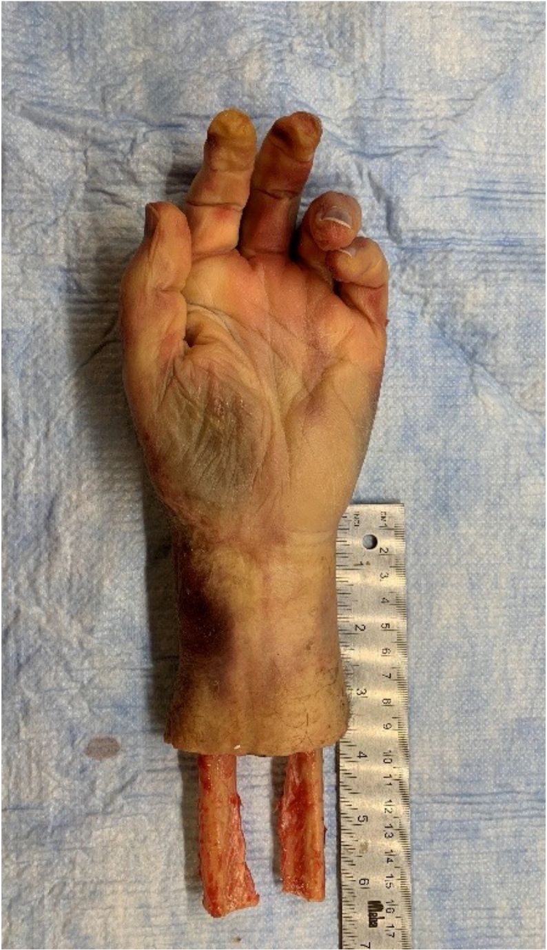
  7. Place the proximal end of the exposed radius and ulna into a table vise and tighten. Using an oscillating saw or handsaw, cut the exposed bone at the 6-inch mark. Following dissection, ensure that the specimen looks like Figure 1.

1.2 Specimen mounting and fixation

  1. Prepare a 3 inch x 3 inch x 3 inch square aluminum extrusion section by sealing the bottom with aluminum foil and lab tape. Ensure that the sealed aluminum extrusion looks like Figure 2A.
  2. Place the forearm specimen hand against the wrist mounting fixture and secure the specimen using trigger clamps as pictured in Figure 2B. The wrist mounting fixture is at a set angle of 15°. Angle the hand and forearm at 15°.
  3. Position the radius and ulna so that they cross each other with the radius behind the ulna (ulna on the palm side), as pictured in Figure 2C. This position mimics a pronated hand position. Center the specimen with the proximal end of the radius and ulna approximately 0.25 inches from the bottom of the extrusion.
    NOTE: A shim may be used to position the square aluminum extrusion such that the radius and ulna are approximately 0.25 inches from the bottom of the extrusion. Variations in hand morphology can lead to these differences in positioning.
  4. Mix self-curing acrylic per manufacturer specifications and fill the extrusion to 0.25 inches to 0.50 inches from the top. For the listed self-curing acrylic, use a ratio of 1 scoop of powder (using a manufacturer-provided scoop) to 10 mL of liquid component. A total of 12 scoops of powder and 120 mL of liquid are generally used per specimen.
  5. Allow the self-curing acrylic to cure for the manufacturer's suggested time. For the listed self-curing acrylic, allow it to cure for 15 min before proceeding to biomechanical testing.

2. Biomechanical test setup and fracture induction

2.1 Biomechanical test setup

  1. Place the biaxial stage on the material testing machine stage, as pictured in Figure 3A. Attach the bottom portion to the material testing machine stage with 4 M10 screws and the top portion to the bottom with 4 M8 screws.
  2. On the top portion of the biaxial stage, attach the extrusion holder with 3 M8 screws as pictured in Figure 3B. Attach the 10 kN load cell to the actuator using 6 M10 screws and attach a 3-inch x 3-inch loading platen to the load cell using 6 M8 screws.
  3. Insert the load and torsion transducers into the material testing machine frame and turn on the machine.
  4. Open the material testing machine software, perform system-required calibrations of the load cell, and set system limits. Raise the actuator to the highest position to allow for full use of the actuator's range of motion.
  5. Place the square extrusion section of the mounted specimen into the extrusion holder on the material testing machine stage, as pictured in Figure 4A. Tighten the two M4 set screws to secure the specimen.
  6. Move the biaxial stage to center the specimen in line with the actuator from left to right. Align the specimen from front to back such that the loading plate covers the breadth of the palm. Use the distal palmar crease, as pictured in Figure 4B, as a common anatomical landmark for aligning the back edge of the loading platen.
  7. Lower the material testing machine frame so that the loading platen is almost touching the palm of the specimen. Monitor the measured load on the material testing machine software to ensure no load is applied to the specimen.
  8. Review the testing setup before continuing fracture induction. Ensure all screws on the biaxial stage and the set screws on the extrusion holder are tightened.

2. 2 Wrist fracture induction

  1. Collect the fracture induction testing data at a Sampling Rate of 100 Hz. Set this data acquisition rate prior to beginning testing. Develop a testing protocol prior to test execution following the steps listed below.
    1. Use an Absolute Ramp Function to pre-load the specimen at a Loading Rate of 0.33 mm/s until a force value of 2 N is reached. At 2 N, the system will Auto-Balance to display the compressive displacement.
    2. Use an Absolute Ramp Function to pre-load the specimen at a Loading Rate of 0.33 mm/s until a force value of 50 N is reached and then move away from the specimen at a Loading Rate of 0.33 mm/s until a force value of 10 N is reached. Then, resume or cancel testing following inspection of the specimen when the system prompts.
    3. Ensure that the specimen wrist is in extension with the loading platen in contact. If the specimen wrist has started to move into flexion, cancel the test and resume the test from step 2.1.6. 
      NOTE: The specimen may require adjustment to move the loading platen further distally on the palm of the hand to ensure that the wrist remains in extension.
    4. Click Resume to proceed in the pop-up prompt window. Use an Absolute Ramp Function to test the specimen to failure at a Loading Rate of 3.3 mm/s with an End-of-Ramp Load Value of 5000 N. Adjust this End-of-Ramp Load Value relative to the capacity of the load cell used. 
      NOTE: End of Test Criteria used are if the measurement rate of the force has a 40% drop, or if the force drops from peak value by 40% after passing 600 N. Once the test protocol ends, the actuator will return to the starting position.
  2. Following completion of the fracture induction protocol, raise the material testing machine frame and loosen the set screws to remove the specimen. Remove the specimen and the cured self-curing acrylic from the square aluminum extrusion.

Zugriff eingeschränkt. Bitte melden Sie sich an oder starten Sie eine Testversion, um diesen Inhalt anzuzeigen.

Ergebnisse

figure-results-1

Figure 1: Dissected forearm specimen. Representative image of a dissected forearm specimen following soft tissue removal and dissection of radius and ulna.

Zugriff eingeschränkt. Bitte melden Sie sich an oder starten Sie eine Testversion, um diesen Inhalt anzuzeigen.

Materialien

Liste der in diesem Artikel verwendeten Materialien
NameUnternehmenKatalognummerKommentare
Disposable ScalpelMedlineCISCALP10 
3” x 3” Square Aluminum ExtrusionMcMaster-Carr6546K65Cut into 3-inch-long sections
7” Curved Surgical ScissorsPremium InstrumentsB01MAYSVBK 
Absorbent PadsNANANo preferred company or catalog number
Aluminum FoilNANANo preferred company or catalog number
Biaxial StageNANAMachined component (see supplemental files)
Biohazard BagsNANANo preferred company or catalog number
Bosworth Fastray Regular Bulk Kit BlueKeystone Industries921386 
Face MaskNANAPPE; No preferred company or catalog number
Instron 10kN Load CellInstron2527-202 
Instron E10000 Mechanical Testing SystemInstronE10000Mechanical Testing Machine
Laboratory Coat or Medical ScrubsNANAPPE; No preferred company or catalog number
Laboratory TapeNANANo preferred company or catalog number
Loading PlatenNANA90 mm ´ 90 mm ´25.4 mm platen (Supplementary materials)
Mixing CupNANAFor mixing self-curing acrylic
Nitrile GlovesNANAPPE; No preferred company or catalog number
Oscillating SawMilwaukeeB00I3PNFVK 
Oscillating Saw BladeEZARCB07YDMX328 
Permanent MarkerNANANo preferred company or catalog number
Rat-Tooth ForcepsA2Z SCILABB07T616T72 
RulerNANANo preferred company or catalog number
Safety GlassesNANAPPE; No preferred company or catalog number
Table ViceHousolution StoreB088LYPS1T 
Trigger ClampDEWALTDWHT831402PK 

Tags

Simulation von Handgelenksfrakturenkadaverischer Unterarmbiomechanische PrüfungKraft-Weg-KurveBeurteilung der KnochenfestigkeitFrakturbeständigkeitmechanische BelastungPronationsstellungradiologische Analyse