This video demonstrates a non-invasive method to assess changes in corticomotoneuronal transmission in humans following repetitive transcranial magnetic stimulation (rTMS). The study introduces an electrophysiological technique that differentiates fast, direct corticospinal pathways from polysynaptic connections.
A subscription to JoVE is required to view this content. Sign in or start your free trial.
Method Article
Repetitive Transcranial Magnetic Stimulation-Induced Changes in Human Corticomotoneuronal Synapses
628 views
⸱
August 29th, 2025
In This Article
Abstract
Protocol
All procedures involving human participants have been performed in compliance with the institutional, national, and international guidelines for human welfare and have been reviewed by the local institutional review board.
1. TMS
1. Stimulate the motor cortical area of the contralateral hemisphere with TMS using a figure eight coil to elicit motor evoked potentials (MEPs) in the electromyographic recordings of the soleus muscle.
2. In order to find the optimal stimulation spot, place the coil first over the vertex and 1 cm frontal. The handle of the coil should point backward, evoking a posterior-to-anterior flux of the induced current in the center of the coil.
3. Start stimulation with low intensities of around 20 - 30% of the maximal stimulator output so that subjects get accustomed to the magnetic stimulus. Choose the pause between successive stimuli to be 4 s.
4. After a few trials, increase stimulation intensity to around 40 - 60% of the maximal stimulator output and move the coil in the frontal-rostral and medio-lateral direction in order to find the hotspot of m. soleus. The hotspot is defined as the position where MEPs in the m. soleus can be evoked with minimum stimulation intensity.
5. After finding the soleus hotspot, determine the resting motor threshold (1.0 MT) as the minimum intensity required to evoke MEP peak-to-peak amplitudes in the EMG larger than 50 μV in six out of ten consecutive trials. In subjects in whom the background EMG is already around 50 μV, use 100 μV as the threshold.
2. Fixation of the Coil
1. Place the subject's head on a table and use rigid foam to prevent head movements in all directions. Fixate the coil to a stand and the subject's head to the chair.
2. Fixate the coil with Velcro strips to the head and use an image-guided TMS navigational system to monitor coil and head position throughout the experiment. Avoid even small movements of the coil relative to the subject's head, as this changes the recruitment of neurons by TMS.
3. Magnetic Stimulation at the Cervicomedullary Junction
1. Use a double-cone magnetic coil placed at the cervicomedullary junction to excite axons of the corticospinal tract.
2. Position the coil so that the first derivative of the induced current is cranially directed and that its central portion is on or near the inion. Apply stimulation with maximum stimulator output (100%).
NOTE: Even with this high stimulation intensity, the stimulus is too weak to sufficiently recruit spinal motoneurons and activate the muscles of the lower leg (i.e., m. soleus and m. tibialis anterior) in most subjects. Thus, with cervicomedullary stimulation, there is no compound potential in the surface EMG of lower leg muscles. Therefore, combine cervicomedullary simulation with the H-reflex to raise the excitability of the spinal motoneurons.
4. Premeasurement
1. Adjust the size of the H-reflex (peripheral nerve stimulation)
1. For H-reflex conditioning, adjust the size of the H-reflex to 20% of the maximum M-wave (Mmax) by changing the stimulation intensity of the electrical stimulator. To obtain Mmax, record an H-reflex recruitment curve. For this purpose, apply stimuli with varying stimulation intensities. The pause between successive trials is 4 s.
2. Calculate H-reflexes and M-waves as peak-to-peak amplitudes in the EMG (in mV) online in the recording software. Take care that the size of the control H-reflex stays constant at 20% of Mmax throughout the experiment and check its size in each trial. When detecting a systematic deviation of the H-reflex size (control H-reflex is always smaller or larger as the target size), adjust the stimulation intensity just prior to the consecutive trial.
2. Adjust the stimulation intensity of TMS prior to the experiment.
1. For H-reflex conditioning at rest, set the stimulation intensity for TMS over the motor cortex to 90 - 100% of MT. Ensure that no MEP is seen in trials without PNS.
NOTE: The simulation intensity should be close to 100% of MT in order to ensure large effects on the conditioned H-reflex at rest so that the early facilitation can easily be detected.
2. Adjust cervicomedullary stimulation intensity prior to the experiment. Unlike cortical stimulation, always adjust stimulation intensity for cervicomedullary stimulation to 100% of the maximum stimulator output.
3. Condition the H-reflex with magnetic stimulation over the motor cortex.
1. Apply TMS and PNS by varying the timing between the two stimuli (H-reflex conditioning) to allow assessment of changes in corticomotoneuronal transmission. To detect the early facilitation, start the conditioning protocol with an interstimulus interval (ISI) of -5 ms and alter ISIs in steps of milliseconds, from -5 - +1 ms (Figure 1B).
NOTE: Negative ISIs indicate that PNS is elicited before TMS; positive ISIs indicate the opposite.
2. Vary the ISI between TMS and PNS randomly from stimulation trial to stimulation trial so that no bias due to a certain order of stimuli may arise.
NOTE: The "early facilitation" should occur around ISIs -4 ms to -2 ms when applying TMS over the motor cortex. This means that the fastest (monosynaptic corticospinal pathways) collide with the afferent volley by PNS at the spinal motoneurons at this time (see 3.2 for detecting the early facilitation).
3. Set the pause between successive stimulation trials to 4 seconds.
4. Condition the H-reflex with magnetic stimulation over the cervicomedullary junction.
NOTE: Using cervicomedullary stimulation for conditioning, excitation of the corticospinal pathways is spatially closer to the spinal motoneurons than with stimulation of the motor cortex. Therefore, the ISI corresponding to the early facilitation is shifted by approximately 3 - 4 ms. As an example, the early facilitation with TMS over the primary motor cortex at -4 ms would correspond to an ISI between -7 - -8 ms with cervicomedullary stimulation.
- Use ISIs between ISI-9 - -3 ms in steps of 1 ms for cervicomedullary conditioning. Apply ISIs for TMS over the motor cortex and TMS over the cervicomedullary junction always together in one trial, and record a control H-reflex and a control MEP in this trial, too. Use the control H-reflex as a reference for the conditioned H-reflexes and the control MEP to ensure comparable stimulation conditions. Record (at least) ten trials in the pre-measurement.
5. Alternating Stimulation over the Motor Cortex and Cervicomedullary Junction
1. Apply conditioning of the SOL H-reflex by magnetic stimulation of the motor cortex (M1-conditioning; see 2.1) and by magnetic cervicomedullary stimulation (CMS-conditioning; see 2.2) in random order during the same trial.
NOTE: It is recommended to alternately apply M1- and CMS-conditioning in one and the same trial in order to refer the conditioned H-reflexes to the same sample of control H-reflexes (see Figure 1).
6. Intervention - Slow Repetitive TMS
1. Set the stimulation intensity to 1.2 MT, which induces a long-lasting suppression of corticospinal excitability required as H-reflex conditioning takes several minutes to accomplish. During the rTMS intervention, apply TMS over the primary motor cortex at 1 Hz for 20 min.
Access restricted. Please log in or start a trial to view this content.
Results
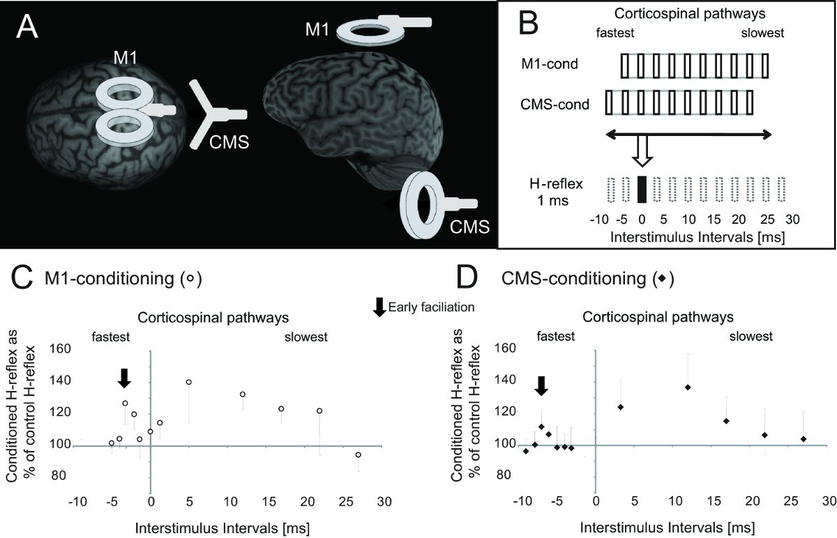
Figure 1: Procedure of M1- and CMS-conditioning. This modified figure from one of our previous publicati...
Access restricted. Please log in or start a trial to view this content.
Materials
| Name | Company | Catalog Number | Comments |
|---|---|---|---|
| Self-adhesive EMG electrodes | Blue sensor N, Ambu, Ballerup, Denmark | Used to record EMG signals | |
| Electrical stimulator | Digitimer DS7A, Hertfordshire, UK | Used to elicit the soleus H-reflex | |
| Stimulating electrode | Blue sensor N, Ambu, Ballerup, Denmark | Used to elicit the soleus H-reflex | |
| Magnetic stimulator #1 | Magstim Rapid2 TMS stimulator, Magstim Company Ltd., Whitland, UK | Used to elicit contralateral motor evoked potentials in the soleus muscle | |
| Coil #1: 90 mm figure-of-eight coil | Magstim Company Ltd., Whitland, UK | Used to elicit contralateral motor evoked potentials in the soleus muscle | |
| Magnetic stimulator #2 | MagPro X100 with MagOption, MagVenture A/S, Farum, Denmark | Used to elicit contralateral motor evoked potentials in the soleus muscle | |
| Coil #2: 95 mm focal “butterfly shaped” coil (D-B80) | MagVenture A/S, Farum, Denmark | ||
| Magnetic stimulator #3 | Magstim Company Ltd., Whitland, UK | Used to stimulate at the cervicomedullary junction | |
| Coil #3: double-cone magnetic coil | Magstim Company Ltd., Whitland, UK | Used to stimulate at the cervicomedullary junction | |
| Image-guided TMS navigational system #1 | Brainsight 2, Rouge Research, Montreal, Canada | Used to monitor coil position throughout the experiment | |
| Image-guided TMS navigational system #2 | TMS Navigator SW-Version 2.0, LOCALITE GmbH, Sankt Augustin, Germany | Used for the video session |
