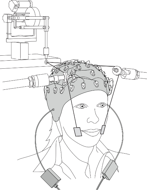
All procedures involving human participants have been performed in compliance with the institutional, national, and international guidelines for human welfare and have been reviewed by the local institutional review board.
1. Electroenchephalopgaphy (EEG) Preparation
- Measure head size to determine the appropriate EEG cap.
- Identify the location of the vertex by finding the mid-point between nasion and inion with a measuring tape.
- Place the EEG cap on the head using the pre-determined vertex as Cz. Examine the midline central region of the head (Cz) again after placing the cap by using a measuring tape as done in 1.2. Note that the EEG cap is equipped with electrode holders and the placement of the 64 electrodes (or holders) is based on a modified 10-20 system with a pre-specified coordinates system based on Cz.
NOTE: This representative application uses a 64-electrode configuration to assess scalp distribution changes and for source analysis. For simpler applications (event-related potential changes in amplitude and latency) using fewer electrodes are possible. There are two additional electrodes for ground in the EEG system used here. Those electrode holders are also included in the cap.
- Apply electrode gel in the electrode holders using a disposable syringe.
- Attach EEG electrodes (including ground electrodes) into the electrodes holders matching the labels of the electrodes and to the electrode holders on the electrode cap.
- Clean the skin surface with alcohol pads.
NOTE: For electrodes for detecting eye motion (electro-oculography), the skin locations are above and below the right eye (vertical eye motion), and lateral to the outer canthus of both eyes (horizontal eye motion); for somatosensory stimulation the skin lateral to the oral angle is cleaned.
- Fill the four electro-oculography electrodes with the electrode gel and secure the electrodes with double-sided tape to the sites noted in 1.6.
- Secure all electrode cables using a Velcro strap. If required, tape the cables to the participant's body or other locations that do not introduce any additional electrical or mechanical noise.
- Position the participant in front of the monitor and the robot for somatosensory stimulation. Secure all electrode cables again as in 1.8.
- Connect the EEG and electro-oculography electrodes (including the ground electrodes) into the appropriate connectors (matching label and connecter shape) on the amplifier box of the EEG system.
- Check to see that the EEG signals are artifact-free and that the offset value is in an acceptable range (<50 µV or smaller). If noisy signals or large offsets that are usually indicative of high impedance are found, correct those electrode signals by adding additional EEG gel and/or repositioning hair that is directly under the electrode.
- Insert the EEG-compatible earphones and confirm that the sound level is in a comfortable range based on the subject report.
2. Somatosensory Stimulation
NOTE: The current protocol applies facial skin stretch for the purpose of somatosensory stimulation. The experimental setup with the EEG system is represented in Figure 1. The details of the somatosensory stimulation device have been described in the previous studies. Briefly, two small plastic tabs (2 cm wide and 3 cm height) are attached with double-sided tape to the facial skin. The tabs are connected to the robotic device using string. The robot generates systematic skin stretch loads according to experimental designs. The setup protocol for ERP recording is as follows:
- Place the participant's head in the headrest in order to minimize head motion during stimulation. Remove carefully the electrode cables between the participant's head and headrest.
- Ask the participant to hold the safety switch for the robot.
- Attach plastic tabs to the target skin location using double-sided tape for somatosensory stimulation. For the representative results, in which the target is the skin lateral to the oral angle, place the center of the tabs on the modiolus, a few mm lateral to the oral angle with the center of the tabs at approximately the same height as the oral angle.
- Adjust the configuration of the string, string supports and the robot in order to avoid EEG electrodes and cables.
- Apply a few facial skin stretches (one cycle sinusoid at 3 Hz with a maximum force of 4 N) to check for artifacts due to the stimulation (usually observed as relatively large amplitude and lower frequency compared with the electrophysiological response). If artifacts are observed in the EEG signals, go back to 2.4.
3. ERP Recording
- Explain the experimental task to the subject and provide practice trials (one block = 10 trials or less) to confirm if the subject understands the task clearly.
NOTE: The experimental task and stimulus presentation for ERP recording are preprogrammed in software for stimulus presentation.
- In the representative test with combined somatosensory and auditory stimulation, apply the somatosensory stimulation associated with skin deformation to the skin lateral to the oral angle. The pattern of stretch is a one cycle sinusoid (3 Hz) with a maximum force of 4 N. A single synthesized speech utterance that is midway in a 10-step sound continuum between "head" and "had" is used for auditory stimulation.
- Present both stimulations separately or in combination. In the combined stimulation, test three onset timings (90 msec lead and lag, and simultaneous in somatosensory and auditory onsets: see Figure 2A).
- Randomize the presentation of five stimulations (somatosensory alone, auditory alone and three combined: lead, simult. and lag). Vary the inter-trial interval between 1,000 and 2,000 msec in order to avoid anticipation and habituation. The experimental task is to identify whether the presented speech sound, which is the sound that is acoustically intermediate between "head" and "had', was "head" by pressing a key on a keyboard. In the somatosensory alone condition, in which there is no auditory stimulation, the participants are instructed to answer not "head".
- Record participant judgments and the reaction time from the stimulus onset to the key press using the software for stimulus presentation. Ask the participant to gaze a fixation point on the display screen in order to reduce artifacts due to eye movement.
- Remove the fixation point every 10 stimulations for a short break.
- Start the software for ERP recording at 512 Hz sampling, which also records the onset time of stimulation in the timeline of ERP data. Note that the time stamps of the stimulation, which also include the information about the type of stimulation, are sent for every stimulus from the software for stimulus presentation. The two programs (for ERP recording and for the stimulus presentation) are running on two separate PCs that are connected through a parallel port.