This video demonstrates the method of juxtacellular recording and staining in a restrained, awake rat. The procedure involves recording signals from neurons and injecting dye to precisely localize the recording site. This technique allows accurate mapping of neural activity to the brain's anatomical structure.
A subscription to JoVE is required to view this content. Sign in or start your free trial.
Method Article
Juxtacellular Recording and Staining for Precise Mapping of Neural Activity in an Awake Rat
641 views
⸱
June 18th, 2025
In This Article
Abstract
Protocol
All procedures involving animal models have been reviewed by the local institutional animal care com-mittee and the JoVE veterinary review board.
1. Juxtacellular Monitoring of Neuronal Units
- Pull quartz capillary tubing on a carbon dioxide laser micropipette puller (see Materials section) with tip diameters of less than 1 μm (Figure 2A).
NOTE: The heating parameters will vary according to the particular instrument, and that the required neck diameter will vary depending on the brain structure of interest. For recordings in rat thalamus, micropipettes have necks ranging from 5-7 mm. - Secure the pipette in place under a differential interference contrast (DIC) microscope equipped with long working distance objectives. Use modeling clay to hold the pipette in place on the microscope’s stage.
- Slowly move a glass block (0.5 - 1 cm thick; a piece of glass used for making ultra-microtome knives is convenient) into the field of view with the pipette tip. Using the stage micromanipulator, gently touch the pipette tip to the glass, causing it to break. Repeat as necessary until the pipette tip outer diameter is between 1-3 μm (Figure 2B, C). Ensure that these micropipettes have impedances between approximately 5-15 MΩ.
- Prepare extracellular saline (135 mM NaCl, 5.4 mM KCl, 1.8 mM CaCl2, 1 mM MgCl2, 5 mM HEPES (4-(2-hydroxyethyl)piperazine-1-ethanesulfonic acid), pH 7.2 with NaOH) and add 2% (w/v) Chicago Sky Blue. Fill the back end of the pipette with the solution using a syringe with a 30 G needle or smaller. Alternatively, for single-cell juxtacellular labeling, add 2% (w/v) Neurobiotin or biotinylated dextran amine (BDA-3000 or BDA-10000) to the saline solution in place of Chicago Sky Blue.
- Place the rat inside the cloth sock inside the rigid tube on an appropriate experimental jig (Figure 1). Wait a minimum of 72 hr after surgery before placing the animal on the head-restraint jig. Tighten the drawstring around the upper sternum, rather than the neck, to avoid obstruction of the airway. If breathing appears to be labored or obstructed, loosen the drawstring or move it posteriorly. Carry out this procedure while the rat is alert.
- Attach the head-restraining plate on the rat to the corresponding piece on the jig. To do this, first pin the head-restraint plate in place, and then secure it using a 4-40 screw. Be sure to wait until the animal is calm in order to avoid applying excessive torque to the head. Next, place an 8-32 nut on the head-restraining bolt that is implanted in the rat. Then screw in a threaded stainless-steel rod to the head bolt. Affix the rod to the experimental jig in such a way that it can be tightened in place (Figure 1).
NOTE: Securing the animal with the head bolt as well as the head-restraint plate minimizes the bending of the apparatus and improves recording stability. In most cases, recording can commence on the first day the animal is head-restrained. However, if the animal fidgets excessively or vocalizes, provide one day of head-restraint habituation training before commencing any recordings. In this case, leave the animal on the jig for 15 min and then place it back in its cage. Repeat this step the following day and continue with the protocol. - Open the recording chamber and remove the silicone gel. If tissue has regrown in the craniotomy, clean it using fine forceps.
- Attach the pipette to the motorized micromanipulator, and plug in the headstage pre-amplifier.
NOTE: In the present demonstration, a small relay circuit on the head stage switches between the amplifier lead wires and an external current source with high compliance(Figure 3A-C). Note that some amplifiers have an appropriate built-in high-compliance source. - Use the motorized micromanipulator to move the tip of the pipette to the stereotaxically identified mark in the recording chamber. Note the coordinates of this location. Be careful not to break the tip of the pipette on the cranium.
- Move the pipette to the desired recording location in the anterior-posterior and mediolateral axes. Then advance the pipette ventrally through the dura until it is approximately 500 μm dorsal to the intended recording location.
- Slowly advance the pipette while listening for spiking events on an audio monitor of the amplified voltage recorded between the pipette tip and the reference wire. Once spiking events are identified, continue to move the pipette 0-100 μm until positive-going voltage deflections greater than approximately 500 μV are observed.
NOTE: The electrode resistance will increase by a factor of approximately 1.5-10 when this occurs. - Recording should begin once a unit has been isolated, along with all other behavioral and physiological measures of interest. In the present demonstration, self-generated vibrissa movements are monitored with high-speed videography (see Materials section).
- To label the recording site, switch the electrode leads to connect to the current source. There are several ways to do this, using either a relay circuit(Figure 3A-C), a built-in current source on the amplifier, or manually(Figure 3D). Pass -4 μA with 2-sec pulses at 50% duty cycle for 4 min to iontophoretically inject Chicago Sky Blue through the pipette.
- Kill and perfuse the animal after several labeling procedures according to standard practice. Section the brain and counterstain as necessary to identify the anatomical location of the recording site. Counterstain the tissue for cytochrome oxidase reactivity. Alternatively, identify the Chicago Sky Blue deposits using fluorescence microscopy.
NOTE: To accurately differentiate between different labeled units, it is important that all labels are made with the same pipette on the same day, without unclamping the pipette between labels. In this case, recording sites can be differentiated by their relative locations in post-hoc histology, along with the noted manipulator coordinates of each site. For unambiguous identification, mark the labels at least 200 μm apart from one another, and no more than 3-5 labels per brain region.
Access restricted. Please log in or start a trial to view this content.
Results
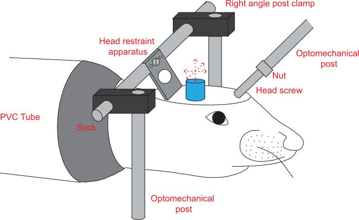
Figure 1: Experimental jig. Diagram of rat in the mechanical jig for electrophysiological and beh...
Access restricted. Please log in or start a trial to view this content.
Materials
| Name | Company | Catalog Number | Comments |
|---|---|---|---|
| Ketaset (Ketamine HCl) | Fort Dodge | N/A | |
| Anased (Xylazine solution) | Lloyd Laboratories | N/A | |
| Betadyne (Povidone-Iodine) | CVS Pharmacy | 269281 | |
| Loctite 495 | Grainger Industrial Supply | 4KL86 | 20-40 cp cyanoacrylate |
| Vetbond | 3M | 1469SB | |
| Grip cement powder | Dentsply Intl | 675571 | For the base of the recording chamber |
| Grip cement liquid | Dentsply Intl | 675572 | For the base of the recording chamber |
| Silicone Gel | Dow Corning | Mar-80 | |
| Jet denture repair acrylic powder | Lang Dental Manufacturing Co. | N/A | For securing the head restraint apparatus to the cranium |
| Ortho-Jet Fast curing orthodontic acrylic resin liquid | Lang Dental Manufacturing Co. | N/A | For securing the head restraint apparatus to the cranium |
| Chicago sky blue | Sigma | C8679 | |
| Paraformaldehyde | Sigma | 158127 | For perfusion and tissue fixation |
| Phosphate-buffered saline | Sigma | P3813 | For perfusion and tissue fixation |
| Cytochrome C | Sigma | C2506 | |
| Diaminobenzidine | Sigma | D5905 | |
| Rat sock | Sew Elegant (San Diego, CA) | N/A | |
| PVC tube 2 ½” | U.S. Plastic Co. | 34108 | |
| Subminiature D pins & sockets | TE Connectivity | 205089-1 | |
| Stainless steel music wire 0.010” diameter | Precision Brand Products, Inc. | 21010 | |
| Stereotaxic holding frame | Kopf Instruments | Model 900 | |
| Stereotaxic ear bars | Kopf Instruments | Model 957 | |
| Stereotaxic manipulator | Kopf Instruments | Model 960 | |
| ½ mm drill burr | Henry Schein | 100-3995 | |
| Quiet-Air dental drill | Midwest Dental | 393-1600 | |
| Stainless steel 0-80 1/8” screw | Fastener superstore | 247438 | |
| 0.2mL centrifuge tube | Fisher Scientific | 05-407-8A | |
| Custom head-holding bar | UCSD SIO Machine Shop | N/A | |
| Right angle post-clamp | Newport | MCA-1 | |
| 8-32 3/4” screw | Fastener Superstore | 240181 | |
| 4-40 ¼” screw | Fastener Superstore | 239958 | |
| Quartz capillary tubing | Sutter Instruments | QF-100-60-10 | |
| Motorized micromanipulator | Sutter Instruments | MP-285 | |
| Microelectrode amplifier | Molecular Devices | Multiclamp 700B | Alternate part: Molecular Devices Axoclamp 900A |
| Microelectrode amplifier head stage | Molecular Devices | CV-7B | Alternate part: HS-9Ax10 with Molecular Devices Axoclamp 900A |
| Isolated pulse stimulator | A-M Systems | Model 2100 | Alternate part: HS-9Ax10 with Molecular Devices Axoclamp 900A |
| Audio monitor | Radio Shack | 32-2040 | |
| Electrode lead wire | Cooner wire | NEF34-1646 | |
| Relay for amplifier head-stage | COTO Technology | #2342-05-000 | (optional) Used with a custom-made printed circuit board (UCSD Physics Electronics Shop), Figure 6A-C |
| Digital video camera | Basler | A602fm | |
| Pipette holder | Warner Instruments | #MEW-F10T | |
| Custom head-holding plate | UCSD SIO Machine Shop | N/A |
