Cryo Electron Microscopes, either Scanning (SEM) or Transmission (TEM), are widely used for characterization of biological samples or other materials with a high water content1. A SEM/Focused Ion Beam (FIB) is used to identify features of interest in samples and extract a thin, electron-transparent lamella for transfer to a cryo-TEM.
Method Article
Cryo-electron Microscopy Specimen Preparation By Means Of a Focused Ion Beam
In This Article
Summary
Abstract
Here we present a protocol used to prepare cryo-TEM samples of Aspergillus niger spores, but which can easily be adapted for any number of microorganisms or solutions. We make use of a custom built cryo-transfer station and a modified cryo-SEM preparation chamber2. The spores are taken from a culture, plunge-frozen in a liquid nitrogen slush and observed in the cryo-SEM to select a region of interest. A thin lamella is then extracted using the FIB, attached to a TEM grid and subsequently thinned to electron transparency. The grid is transferred to a cryo-TEM holder and into a TEM for high resolution studies. Thanks to the introduction of a cooled nanomanipulator tip and a cryo-transfer station, this protocol is a straightforward adaptation to cryogenic temperature of the routinely used FIB preparation of TEM samples. As such it has the advantages of requiring a small amount of modifications to existing instruments, setups and procedures; it is easy to implement; it has a broad range of applications, in principle the same as for cryo-TEM sample preparation. One limitation is that it requires skillful handling of the specimens at critical steps to avoid or minimize contaminations.
Introduction
In this protocol a cryo-FIB/SEM is used to produce TEM samples from a specific region of the sample, previously identified with high precision by SEM analysis. Electron microscopy (scanning or transmission) analysis of biological samples is a routine technique used for research and diagnostic. SEM is rather fast and easy to employ and interpret, but information is obtained only from the sample surface and with a resolution in the 1.5 nm range. TEM has a higher resolution but is more difficult to implement, the image analysis is less straightforward and whereas bulk information is obtained, samples have to be thinned to electron transparency (less than about 500 nm thick). An additional problem is that the vacuum requirements of those instruments are rarely tolerated by water-containing samples. In most cases, biological samples have to be either chemically fixed (substituting water with, for example, polymers) or dried. In both cases, significant changes to the morphology and structure of the specimen are likely to occur. Cryo TEM preparation of hydrated specimens induces minimal chemical changes and it produces samples as close as possible to their native state, especially if vitrification of ice is obtained1-6.
The FIB is widely used to prepare TEM samples for its numerous advantages7. To name a few: the use of high-energy ions at near-normal incidence minimizes the effect of material-related differential milling rates; the region extracted from the bulk sample can be chosen with a sub-micron precision; a very small amount of material is extracted. Some recent technical developments have made possible using the FIB also for TEM sample preparation at cryogenic temperatures2,8-10. There are several advantages over the traditional preparation method of cryo-microtomy11,12 used mainly for soft matter samples, such as the lack of mechanical deformation of the sliced lamella, the absence of knife marks and the possibility to prepare composite samples with hard/soft interfaces or components.
Protocol
NOTE: all parameters given in this protocol are valid for the instruments and models indicated here. Some of those parameters (marked by * in the text) may differ if another manufacturer or model is used.
1. Start-up of the FIB/SEM
- Mount the custom-built cold nanomanipulator (NM) tip without attaching the Cu braids to the anticontaminator (AC). Instead make sure the braids are connected to the rest of the NM above the insulation point to prevent charge up during the sharpening step (1.2).
- Close the SEM chamber, pump to high vacuum and image the NM tip.
- If the tip is blunt, bent or contaminated by previous use, sharpen it by means of the ion beam: select polygonal milling patterns along the sides of the tip, so that after milling, the tip will taper down to 1 µm or less.
- Once the sides of the tip have been milled away, manually rotate by 90° the entire NM rod from outside the SEM chamber.
- Adjust the polygonal milling patterns to adapt to the rotated tip and repeat milling from a different angle.
- Once the tip has been sharpened to be less than 1 µm, retract the NM and insert the needle of the Gas Injection System (GIS); reposition the needle to be at about 1 mm above the working distance (instead of the usual 175 µm).
- If using a Pt precursor, change its operating temperature to 24-26 °C (instead of the usual 40 °C). These steps are needed for cryo-deposition13 of the Pt.
- Open the SEM chamber and prepare the FIB/SEM for cryo-mode by mounting the cryo sample stage and the AC.
- Switch the NM to the inserted position and connect its Cu braids to the AC. Make sure to not accidentally touch the NM tip. The system is cooled with the NM inserted to make sure that the loss of flexibility of the Cu braid at cryogenic temperatures will not hamper the NM movement.
- Purge the pipes for cooling with dry nitrogen gas for a few minutes.
- Pump the cryo preparation chamber and the main sample chamber to high vacuum.
- Add liquid nitrogen to the Dewars to cool both chambers. Wait until the desired temperature is reached.
2. Sample Freezing
-
- Mount two TEM grids for FIB samples on the SEM transfer holder. Secure them by tightening the corresponding screws with a screwdriver.
- Mount a sample stub appropriate for the specimen and add a portion of the specimen. Depending on the type of sample, the specimen can be fixed with cryogenic glue or with a clamp. Use amounts as small as possible to ensure optimal freezing.
- Mount the SEM transfer holder onto the vacuum transfer device (VTD).
-
- Add liquid nitrogen into the slushing station and pump down to obtain nitrogen slush.
- Open the slushing station and plunge-freeze the SEM transfer holder. Pump down again until boiling is completed and slush is obtained again. It should be noted that an ethane or propane slush or high pressure freezing are better suited techniques to obtain the vitrification of the sample.
-
- Retract the SEM transfer holder into the vacuum chamber of the VTD and seal it.
- Vent the slushing station and the cryo preparation chamber airlock.
- Match the VTD seal with the airlock of the cryo preparation chamber and pump.
- When a good vacuum level is reached, engage the airlock pin to open the seal of the VTD and the outer airlock; insert the SEM transfer holder. There are markings on the sliding contacts in the preparation chambers indicating the sample position for sputtering and fracturing.
- If necessary, the sample can be: fractured with the cold knife; sublimated by setting a higher temperature (usually -100 °C); coated with Au/Pd or Pt by means of the cold sputterer (300 V, 10 mA, 60 sec for a 2-3 nm Au/Pd cap)*. Sublimation should not be used for vitrified samples to avoid their recrystallization.
-
- Use the cold knife to open the protective lids of the TEM grid slots.
- Bring the cold stage in the sample chamber to the receiving height (16 mm*).
- Switch off the HT on the FIB/SEM and open the inner airlock.
- Use the VTD to transfer the SEM holder into the sample chamber. Dimming the lighting in the room may help in this step.
- Once the SEM holder is in the cold stage, disengage the VTD by pushing and rotating.
- Retract the VTD rod all the way into the VTD vacuum chamber and close the inner airlock, the outer airlock and the VTD seal. The outer airlock can now be vented to remove the VTD seal. This last step is not required, but it is recommended as the VTD rod may be easily dislodged by accident, which may cause damage to the VTD or the airlock.
3. Ion Milling
- Turn on the high tension on both columns and set the appropriate imaging parameters (accelerating voltage: 10 kV for the electron beam, 30 kV for the ion beam; spot size: 3; working distance: 5 mm, ion beam current: 10-100 pA for imaging, 1-3 nA for milling)*.
- Use the electron beam to find a feature of interest and to acquire images to document the status of the sample before the extraction of the lamella.
- Once a region of interest (ROI) for extraction has been identified, mark it by ion beam patterning, unless the topography of the sample itself allows for an easy identification of the ROI even after Pt deposition. For increased precision, use the method described by Pettersson et al.14 The markings should be deep, wide and far enough to be still visible after being covered by the cryo-Pt deposition (which is non-selective and will cover several mm2 of the sample surface).
- Heat the precursor gas to 24-26 °C and insert the GIS needle to a height of about 1 mm above the sample surface (see also step 1.3).
- While imaging with the electron beam, open the gas valve for a few seconds. The rate of cryo-Pt deposition is 100-500 nm/sec or more, depending on the distance of the GIS needle, the sample roughness and the user’s system. It is advisable to run a few test depositions to determine the optimal parameters.
- The raw cryo-Pt deposition is very rough and inhomogeneous. Cure the deposit over the ROI by using a 1,000 pA ion beam at low magnification (for example 2,000X). Unlike the cryo deposition, this curing is site selective and should be performed on the ROI only. The purpose of this first cryo-deposition is to protect the surface of the sample from ion beam damage and to reduce curtaining during ion thinning13.
- Tilt the sample to 52° so that the surface is perpendicular to the ion beam. Mill away two terraced trenches on either side of the ROI. Typical dimensions for the trenches are 20-30 µm in the direction (X) parallel to the lamella to be extracted, 10-15 µm in the perpendicular direction (Y) and with a variable, sloping depth (Z), with the deepest point close to the ROI. The slope should be 45-55°. In some instruments, terraced trenches can only be milled with the deepest point on top. In such case, mill one under the ROI, then rotate the image 180° and mill the second one on the other side. The depth of milling can be selected if the sputter rate of the material is known. For most frozen-hydrated sample, the sputter rate of ice can be used7.
- Tilt the sample back to 0° and use the ion beam to cut away the sides and underside of the lamella, making sure the cut marks go through the entire lamella (they should leave milling marks on the terraced slopes milled in the previous step). Leave only two small bridges connecting the lamella to the rest of the sample.
- Insert the GIS needle (this may slightly shift the sample). Maneuver the NM until its tip is in physical contact with the lamella, preferably on the side. Make sure the NM is not obstructing the ion beam view of the two small connecting bridges.
-
- Open the GIS valve for a few seconds and monitor the cryo deposition by continuous imaging with the electron beam.
- When an additional 1-2 µm layer of Pt has been cryo-deposited, close the valve.
- Cure the Pt (see step 2.6) only in the few µm around the point where the NM is in contact with the lamella.
- Use a high ion beam current to cut the lamella free. The two connecting bridges should be milled away, as well as any excess of Pt that may have formed new contact points between the lamella and the rest of the sample. Do not retract the GIS needle yet.
- Carefully maneuver the NM to extract the lamella from the trenches and move it at least 500 µm above the sample surface. Only after this step, retract the GIS needle.
- Lower the sample stage a few mm and move it until one of the TEM grids is in view. Move the attachment area on the grid into the working position and insert the GIS needle.
-
- Carefully maneuver the NM to bring the attached lamella into physical contact with the attachment area on the TEM grid. There should be no pressure or tension between the lamella, the TEM grid and the NM.
- Open the gas valve for a few seconds and cryo-deposit an additional 1-2 µm layer of Pt.
- Cure the Pt (see step 2.6) only in the few µm around the point of contact between the lamella and the TEM grid.
- Use a high ion beam current to cut the lamella free of the NM. This can be accomplished by milling away either the NM tip or the side of the sample. In the first case, the tip will have to be sharpened again before the next use, as described in step 1.2.
- OPTIONAL: at this stage it is possible to use the VTD to take the SEM transfer holder and store it O/N in a Dewar filled with liquid nitrogen. This transfer and O/N storage is likely to cause ice formation on the surface of the lamella if ice crystals are already present and/or if the liquid nitrogen is exposed to humid air; but such contamination will be removed by the next step in a relatively short time. As the previous steps may have taken several hours to complete, it could be appropriate to do so, since after the following step such storage O/N is not recommended, as there would be no way to remove the ice contamination except by sublimation (which cannot be performed if vitrification of the sample is to be maintained).
- Tilt the sample to 52° and use the ion beam to thin it to electron transparency7. It is recommended to start with higher, rougher beam currents to remove the bulk and proceed to fine polishing the surface with lower beam currents, eventually also reducing the accelerating voltage. The final thickness of the lamella should be 100-200 nm or less for ultrastructure analysis in a 100-200 kV TEM or up to 500 nm for tomography in a 300 kV TEM, depending on the sample composition. During thinning, the internal stresses of the sample may cause the lamella to curl or bend. In such case, the region thinned should be restricted. This happened for example in the Figures 11 and 12.
4. Cryo Transfer to TEM
-
- Flush the cryo-transfer station with dry nitrogen gas for a few minutes.
- Add liquid nitrogen to the Dewar of the TEM AC and to the cryo-transfer station.
- Insert the cryo-transfer TEM holder in the appropriate slot of the cryo-transfer station and fill its Dewar as well. Wait until each component has reached the desired temperature (about 15 min). If possible, the controller of the cryo-transfer TEM holder should be connected to monitor the temperature during the transfer. It is important to realize that the tip of the TEM holder (where the temperature sensor is located) will be in contact with the cryo-transfer station and will therefore cool down much faster than the rest of the TEM holder. It is therefore recommended that the time needed for the whole cryo-transfer TEM holder to cool down is measured beforehand, and that the system is allowed to thermalize for at least that amount of time.
- Fill a cryogenic cup with liquid nitrogen and immerse in it: the TEM sample clamping tool, a screwdriver and tweezers, in order to cool down their tips to the desired temperature. All tools should be properly insulated on the other end so as not to cause cold burns to the operator’s hand.
- Match the VTD to the outer airlock. Bring the cold stage to the transfer height (16 mm*). Turn off the high tension.
-
- Open the VTD seal, the outer airlock and the inner airlock.
- Use the VTD rod to lock into the SEM transfer holder by pushing and rotating clockwise.
- Retract the SEM transfer holder into the cryo preparation chamber.
- Use the cold knife to close the protective lids of the TEM grids. This is necessary to reduce possible ice contamination during transfer.
- Use the VTD rod to move the sample into the vacuum chamber of the VTD.
- Close the airlocks and seal.
- Vent the outer airlock and detach the VTD. Match the VTD to the SEM port of the cryo-transfer station. While flushing with dry nitrogen, use the pin on the station to open the seal of the VTD and slide the SEM transfer holder into the Dewar of the cryo-transfer station.
-
- Add enough liquid nitrogen so that the level in the cryo-transfer station is high enough to just submerge the sample.
- Use the previously cooled screwdriver to open one of the lids and loosen the corresponding screw that is keeping the TEM grid in place.
- Use the previously cooled tweezers to pick the TEM grid and place it into the TEM holder.
- Use the cooled hexring to fasten the TEM grid onto the TEM holder.
- Close the shutter of the cryo-transfer TEM holder. The sample transfer step is crucial and might be hampered by nitrogen gas reducing the visibility of the small TEM sample.
- Disconnect the cryo-transfer station from the pumping system and transport it near the TEM, together with the heater controller of the cryo-transfer TEM holder.
- Start the turbomolecular pump of the TEM to pump the backing line to the TEM airlock.
- Set the TEM sample stage to a tilt* of -70°.
- Set the shortest pumping time for the airlock (30-60 sec), with only one cycle of purging with dry nitrogen gas.
- Ensure that the protective shutter on the cryo-transfer TEM holder is closed. Remove the TEM holder from the cryo-transfer station and insert it into the tilted goniometer (liquid nitrogen will spill out of the TEM holder Dewar). The pumping cycle will start. Once the cycle is completed, set the goniometer to tilt back to 0° and, at the same time, hold the TEM holder so that it does not rotate with the goniometer. Insert it fully inside the TEM. During this step, the cryo-transfer TEM holder should be connected to its heater controller to monitor the temperature. The procedure to insert the sample holder into the TEM may vary between different TEMs. It is therefore recommended to contact the TEM manufacturer to obtain the appropriate procedure.
- Refill the cryo-transfer TEM holder Dewar. Wait for the vacuum in the TEM to reach an acceptable level.
Results
In this work we made use of: a dual beam FIB/SEM equipped with a nanomanipulator and a cryo-preparation chamber; a TEM with a cryo-transfer holder; a prototype cryo-transfer station. The anticontaminator (AC) blades of the cryo-preparation chamber and the tip of the nanomanipulator (NM) were modified by Gatan. With respect to a standard cryo-preparation chamber, the AC blades are larger to provide a greater heat sink for the NM tip. Moreover, the AC is fitted with clamps for connecting the Cu braids for heat exchange with the NM tip. The pneumatics of the FIB/SEM were modified to allow the NM to be and remain inserted even when the sample chamber was vented. It should be noted that the parameters used in this work are best suited for the equipment listed above; those parameters may needed to be adjusted when working with other types of equipment. To work with this protocol, the normal precautions for handling cryogenics, liquid nitrogen and vacuum systems should be followed.
The method has been tested on different types of samples with good results, ranging from solutions or polymer matrices containing nanoparticles, to single-celled organism to nematodes. Examples of the various steps of the procedure are illustrated in Figures 1-12 on A. niger spores stained with osmium tetroxide and potassium permanganate. The spores are first imaged by SEM (Figure 1) to identify the site for extraction. In this case, a cross section of any spore was sufficient, but it is possible to position the ROI for extraction with sub-micrometer precision to, for example, slice a specific cell at a specific distance from the cell membrane. Once the feature of interest has been identified, the first step of the cryo-Pt deposition is implemented (Figure 2), to protect the sample from beam damage from the ion milling. The sample is tilted to 52° to proceed with the first steps of the milling (Figure 3): the sputtering of two trenches on both sides of the lamella. The sample is then tilted back and further milled to leave only two small bridges connecting it to the bulk (Figure 4). The cooled nanomanipulator is brought into contact with the lamella (Figure 5) and another cryo-deposition of Pt solders them together (Figure 6). The small connecting bridges are then milled away and the NM moves the lamella near the attachment area of the TEM grid (Figure 7), where it is soldered with a final cryo-deposition of Pt (Figure 8). The NM is then separated from the lamella (Figure 9), which is thinned down to electron transparency with the ion beam (Figure 10 and 11). The lamella is finally transferred to the TEM (Figure 12) where high resolution imaging, spectroscopy, tomography and other techniques can be employed.

Figure 1. Cryo-SEM image of spores of A. niger, before Pt deposition.

Figure 2. The same area in Figure 1 after Pt deposition but before curing.

Figure 3. Cryo-SEM image of the same area in Figure 2, tilted 52º, after Pt deposition and curing, with trench milling underway (see step 3.7).

Figure 4. The lamella, ready for lift-out.

Figure 5. The cold nanomanipulator tip makes contact with the lamella.

Figure 6. A second Pt cryo-deposition is used to solder together the nanomanipulator and the lamella.
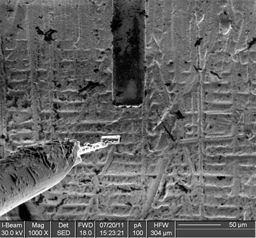
Figure 7. The cold nanomanipulator is used to transfer the lamella to the attachment area of the TEM grid.

Figure 8. Cryo-deposition is used once more to attach the lamella to the TEM grid.

Figure 9. The lamella is cut free of the nanomanipulator and it is now ready for either storage or thinning to electron transparency.

Figure 10. An intermediate step of the thinning, with a few spores visible in cross section.

Figure 11. Cryo-SEM image of the sample after final thinning; most of the other spores had to be milled away because the lamella had started to curl.

Figure 12. A composite cryo-TEM picture of the lamella. Part of the Al stub has been included in the lamella (black arrow).
Discussion
This protocol is a rather straightforward adaptation to cryogenic temperatures of the standard FIB/TEM sample preparation used in material sciences at RT. The method produces TEM samples free of mechanical deformation and knife marks (the major drawback of microtomy), although curtaining may occur if the sample surface is inhomogeneous. This can be reduced by cryo-deposition of a capping layer (in this work Pt was used), cured until it is smooth and featureless13. Samples with components of very different hardness can be prepared as well without the risk that they would break under stress during preparation. Internal stresses may still cause the thin lamella to bend or curl, in which case the size of the section has to be reduced. A drawback compared to other method is the possibility to alter the biological structure due to exposure to the ion beam and possible implantation of the ions in the sample. These drawbacks also occur at RT for sample preparation in materials science15. They can be reduced by completing the thinning with a final polishing step at the lowest accelerating voltage for the ions (500-1,000 V). This very gentle polishing step will remove the damaged layer from the lamella.
Due to the nature of the cryo-deposition (steps 3.5, 3.10 and 3.13), large parts of the sample will be covered, thereby obstructing the view of the original surface. This may make it difficult to keep track of the ROI, unless multiple markings are used as suggested in step 3.3.
During steps 4.5 and 4.7 the thin lamella risks coming in contact with air. This has to be avoided as it would cause the moisture in the air to form ice crystals on the surface of the sample, possibly to the point of obscuring important features. Those steps should be performed as quickly as possible, but at the same time a mishandling during the transfer is likely to result in the loss of the sample itself. It is recommended that the user practices those steps by using empty TEM grids before an attempt on a real sample is made.
In material science, the FIB instrument has become the chief method of TEM sample preparation within a decade of its commercialization. Since it can be used on virtually any specimen, it removes the need to tailor the preparation technique to the type of sample. We strongly believe the same could happen at cryogenic temperatures, thanks to the procedure detailed here. Its application to larger samples is still subject to the ability to cryo-preserve them in a vitrified state, but techniques such as plunge-freezing or high-pressure freezing3,5 can prove to be the optimal solutions to this problem.
Disclosures
Authors have nothing to disclose.
Acknowledgements
This research received support from the QNano Project http://www.qnano-ri.eu which is financed by the European Community Research Infrastructures under the FP7 Capacities Programme (Grant No. INFRA-2010-262163).
We also thank the research council Formas for financial support.
Materials
| Name | Company | Catalog Number | Comments |
|---|---|---|---|
| Strata DB 235 | FEI | FIB/SEM | |
| Omniprobe 100 | Oxford Instruments | Nanomanipulator | |
| Alto 2500 | Gatan | Cryo preparation chamber | |
| Cryo-holder model 626 | Gatan | Cryo transfer TEM holder | |
| Tecnai F30 | FEI | TEM |
References
- Echlin, P. Low Temperature Microscopy and Analysis. , Plenum Press. New York. (1992).
- Rubino, S., et al. A site-specific focused-ion-beam lift-out method for cryo Transmission Electron Microscopy. J. Struct. Biol. 180, 572(2012).
- Studer, D., et al. A new approach for cryofixation by high-pressure freezing. J. Microsc. 203, 285(2001).
- Umrath, W. Cooling bath for rapid freezing in electron microscopy. J. Microsc. 101, 103(1974).
- Walther, P. Recent progress in freeze-fracturing of high-pressure frozen samples. J. Microsc. 212, 34(2003).
- Elder, H. Focused ion beam micromachining of eukaryotic cells for cryoelectron tomography. Cryo fixation. Techniques in Immunocytochemistry. , Academic Press. London. (1989).
- Giannuzzi, L. A., Stevie, F. A. Introduction to Focused Ion Beams. , Springer. New York. (2005).
- Marko, M., et al. Focused-ion-beam thinning of frozen-hydrated biological specimens for cryoelectron microscopy. Nat. Methods. 4, 215(2007).
- Hayles, M. F., et al. The making of frozen-hydrated, vitreous lamellas from cells for cryo-electron microscopy. J. Struct. Biol. 172, 180(2010).
- Rigort, A. Focused ion beam micromachining of eukaryotic cells for cryoelectron tomography. J. Struct. Biol. 109, 4449-44 (2012).
- Hsieh, C., et al. Towards high-resolution three-dimensional imaging of native mammalian tissue: electron tomography of frozen-hydrated rat liver sections. J. Struct. Biol. 153, 1(2006).
- McDowall, A. W., et al. Electron microscopy of frozen hydrated sections of vitreous ice and vitrified biological samples. J. Microsc. 131, 1(1983).
- Hayles, M. F., et al. A technique for improved focused ion beam milling of cryo-prepared life science specimens. J. Microsc. 226, 263(2007).
- Pettersson, H., et al. A method for producing site-specific TEM specimens from low contrast materials with nanometer precision. Microsc. Microanal. 19 (1), 73(2013).
- Wätjen, J. T., et al. Cu out-diffusion in kesterites—A transmission electron microscopy specimen preparation artifact. Appl. Phys. Lett. Appl. Phys. Lett, 051902(2013).
Reprints and Permissions
