Transcranial magnetic stimulation, electromyography, and 3D motion capture are commonly used non-invasive techniques for investigating neuromuscular function in humans. In this paper, we describe a protocol that synchronously samples data generated by all three of these tools along with the unique addition of virtual reality stimulus presentation and feedback.
A subscription to JoVE is required to view this content. Sign in or start your free trial.
Method Article
Multifunctional Setup for Studying Human Motor Control Using Transcranial Magnetic Stimulation, Electromyography, Motion Capture, and Virtual Reality
In This Article
Summary
Abstract
The study of neuromuscular control of movement in humans is accomplished with numerous technologies. Non-invasive methods for investigating neuromuscular function include transcranial magnetic stimulation, electromyography, and three-dimensional motion capture. The advent of readily available and cost-effective virtual reality solutions has expanded the capabilities of researchers in recreating “real-world” environments and movements in a laboratory setting. Naturalistic movement analysis will not only garner a greater understanding of motor control in healthy individuals, but also permit the design of experiments and rehabilitation strategies that target specific motor impairments (e.g. stroke). The combined use of these tools will lead to increasingly deeper understanding of neural mechanisms of motor control. A key requirement when combining these data acquisition systems is fine temporal correspondence between the various data streams. This protocol describes a multifunctional system’s overall connectivity, intersystem signaling, and the temporal synchronization of recorded data. Synchronization of the component systems is primarily accomplished through the use of a customizable circuit, readily made with off the shelf components and minimal electronics assembly skills.
Introduction
Virtual reality (VR) is rapidly becoming an accessible research tool for use in a number of fields, including the study of human motion. The study of upper limb movement is especially benefited by incorporating VR. Virtual reality permits the rapid customization of experimental parameters designed to investigate specific kinematic and dynamic features of arm movement control. These parameters can be individually adjusted for each subject. For example, the locations of virtual targets can be scaled to ensure identical initial arm posture across subjects. Virtual reality also allows the manipulation of visual feedback during experiments, which is an invaluable tool in visuomotor research1–5.
The use of realistic VR environments with other biomechanical tools will also permit naturalistic movement scenarios in which to test movement patterns. This arrangement is becoming increasingly valuable to the study and practice of rehabilitation after disease and injury6,7. Mimicking naturalistic movements and environments (e.g. performing movements in a virtual kitchen) in a clinical setting will enable rehabilitation specialists to more precisely describe an individual’s impairments in a real-world context. Highly individualized impairment descriptions will allow for more focused treatment strategies, potentially increasing the efficacy and reducing the duration of rehabilitation.
Combining VR with other tools such as transcranial magnetic stimulation (TMS), surface electromyography (EMG), and full body motion capture, creates an extremely powerful and flexible platform for studying the neuromuscular control of movement in humans. Transcranial magnetic stimulation is a powerful non-invasive method of measuring the excitability and functional integrity of descending motor pathways (e.g. corticospinal tract) through EMG responses such as motor evoked potentials (MEPs)8. Modern three-dimensional motion capture systems also enable researchers to study neuromuscular activity together with resulting movement kinematics and dynamics. This permits the creation of extremely detailed models of the musculoskeletal system as well as the testing of hypotheses regarding the structure and function of neural controllers. These studies will expand our scientific knowledge of the human sensorimotor system and lead to improvements in treatment of musculoskeletal and neurological disorders.
However, one major problem with multifunctional systems is the synchronization of separately recorded data streams (e.g. motion capture, EMG, etc.). The goal of this protocol is to describe a generalizable arrangement of common commercially available systems to simultaneously record biomechanical and physiological measurements during movement. Other investigators using equipment from different manufacturers may have to alter elements of this protocol to fit their specific needs. However, general principles from this protocol should still be applicable.
Access restricted. Please log in or start a trial to view this content.
Protocol
All participants involved in experimentation undergo informed consent procedures approved by the West Virginia University Institutional Review Board (IRB).
1. Overall System Characteristics, Design, and General Experimental Task
Note: The complete setup is comprised of the following major components: EMG equipment and associated digital acquisition (DAQ) equipment; a motion capture system (this protocol incorporates an active LED system); a TMS unit with a figure-of-eight coil and stereotaxic localization equipment; a VR headset and associated computer and software; and a custom synchronization circuit. Figure 1 schematically outlines the connectivity between the protocol components.
- Connection of System Components
- Connect EMG pre-amplifier to main amplifier.
- Connect output of EMG amplifier to DAQ recording equipment input block using BNC or similar connections.
- Connect DAQ recording equipment to dedicated computer that will execute a data acquisition script (supplementary file).
- Connect VR control computer parallel output to custom circuit unit (see next section for details).
- Connect synchronization and motion capture triggering outputs from custom circuit to DAQ recording block alongside EMG signal connections.
- Split motion capture trigger and connect it to the “Analog Input Start” port on the EMG DAQ equipment as well as the trigger connection on the computer that controls motion capture equipment.
Note: The temporal difference between the beginnings of the respective data acquisition streams for the described equipment (motion capture and EMG) can range from 160-190 msec. This temporal difference motivated the design of the synchronization circuit described in this protocol and is likely caused by the software and hardware differences between these two systems. - Connect TMS trigger port on custom circuit unit to BNC input trigger on the TMS control unit.
- Establish network connectivity between the VR and motion capture computers using vendor-provided software and physical network connections.
- Connect VR headset to VR computer and ensure operability with any scripts/programs that display virtual environments to participants.
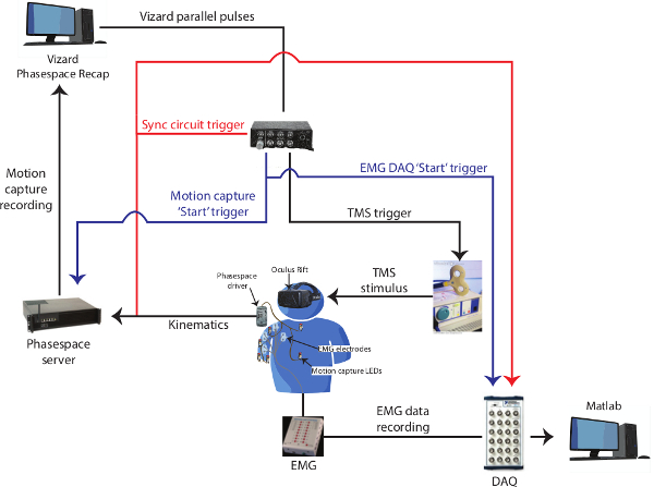
Figure 1: Connectivity of entire setup. This layout describes the general connectivity between the elements of our system. The synchronization circuit is described elsewhere in the text in more detail. The blue trace corresponds to the signal that starts both motion capture and EMG data streams. This event is the source of the temporal delay of up to 190 msec using the equipment described in this protocol. The red trace corresponds to the VR-initiated synchronization event that is concomitantly recorded by the motion capture and EMG systems and subsequently used for temporal alignment of the respective data streams. Please click here to view a larger version of this figure.
2. General Details of System Integration and Synchronization
Note: Synchronization of the separate data acquisition systems in this protocol (motion capture and EMG) is accomplished through the use of an event signal that is common to all recording streams. Using a common event, all of the signals can be temporally realigned after data collection to minimize real-time recording discrepancies (upwards of 190 msec using the equipment in this protocol). In this protocol, the common signal originates from the VR system as a parallel port signal. The common signal is routed to a circuit that permits synchronization of the separate data streams through direct recording with EMG signals and by simultaneously turning off a motion capture LED. The circuit is constructed using basic tools and techniques for building electronic components, similar to circuits described elsewhere9.
- Design, Layout, and Construction of Synchronization Circuit
- Identify any analog TTL-based triggering mechanisms on equipment control units (e.g. TMS, motion capture) and become familiar with triggering requirements such as TTL pulse direction (positive/negative) and amplitude. Analog triggering mechanisms often possess common “BNC” coaxial connectors that make connecting components simple.
- Add an additional LED to the motion capture system to be used for signal synchronization; route the LED’s wires through the synchronization circuit (Figure 3).
- Determine the electrical component parameters (i.e. resistance, capacitance) needed to turn off the synchronizing LED for a specific amount of time. Find the amount of time that the circuit’s syncing LED is turned off by the equation: t = 1.1*R1*C1. This time is suggested to be less than the average duration of an experimental movement. For example, the currently described experiment required a resistor and capacitor rated at approximately one megaohm and one microfarad, respectively.
- Use a soldering iron to adhere electrical components to a printed “protoyping” or “project” circuit board following the schematic shown in Figure 3. Enclose this circuit in a commonly available plastic “project” box; it will likely be necessary to drill holes in this box for the BNC connectors. The circuit can readily be powered by 5 V USB power from a desktop computer; it will be necessary to deconstruct a USB cable to isolate the power and ground wires. Bypass capacitors may also be needed to regulate the power to the 555 chip (not shown in Figure 3).
- Inspect the circuit board for any unintended solder bridges between electrical components. If found, remove solder with a suction tool or heat the solder and mechanically remove the bridging connection.
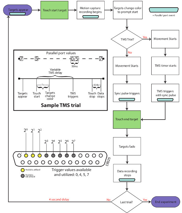
Figure 2: Trial flowchart. This flowchart outlines the stimulus and signal events that occur during a typical experimental trial that includes TMS stimulation. Parallel port codes that occur throughout a trial are shown in the DB25 schematic symbols (light blue).
- Synchronization Details
- Using a flowchart similar to Figure 2, determine when individual pieces of equipment should be triggered during the course of an experimental movement. For example, some equipment may be individually triggered, while others may be simultaneously triggered.
- At time points that require triggering or signaling (e.g. blue parallel port symbols in Figure 2), determine which parallel ports signal lines to use and incorporate them into the VR system. This is accomplished by sending numerical values to the parallel port at the specified times during movements, each line representing a binary digit. For more details about parallel port based signaling, please refer to the Discussion.
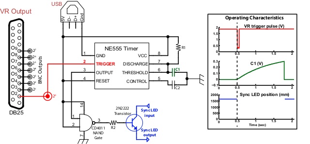
Figure 3: Synchronization Circuit. This schematic displays the layout of our custom synchronization circuit. The default output of the NAND gate is a high voltage state; this voltage output is sent to the gate of a transistor through which the sync LED’s circuit is routed. This default state renders the circuit closed, which maintains the LED in a lighted state. Upon receiving a sync trigger parallel port signal (red trace in inset), an internal state of the 555 device is flipped rendering the output into a high state, shutting off the LED (blue trace). When this occurs, the voltage on C1 (green trace) builds up to a voltage that resets the internal state of the 555, reactivating the LED. The parallel port sync trigger signal is also directly routed to a BNC connector that is connected to the TMS input trigger port. Note: The direction of this trigger signal may have to be reversed (from positive- to negative-going or vice-versa) depending on an investigator’s specific equipment requirements. The addition of an “inverter” chip on this trigger output would easily accomplish this task. Please click here to view a larger version of this figure.
3. Experimental Procedures
- Safety Procedures and Informed Consent
- Ensure that all experimental procedures are approved by an Institutional Review Board (IRB). Explain all procedures to participants and acquire informed consent with IRB approved documentation.
- After acquiring informed consent, conduct a basic TMS safety screening with participants to ensure they do not have tinnitus, a family history of epilepsy or seizures, or other conditions with elevated risks of seizure.
- During TMS stimulation, strictly require the use of protective earplugs to prevent hearing damage.
- Electromyography Collection
- Depending on the scientific goals of a reader’s study, determine from which arm muscles to record EMG signals. For the study described in this protocol, torques generated at the shoulder and elbow during movement were investigated. Thus, EMG signals recorded were from the major superficial muscles that act on these two joints, such as the deltoid, pectoralis, biceps, triceps, and brachioradialis.
- Make all necessary electrical connections between various EMG equipment including amplifiers, preamplifiers, sensor wires, and sensor pads according to the manufacturer’s specifications by connecting matching connectors.
- Prepare each electrode site by lightly cleaning it with an alcohol swab, removing any excessive hair with a razor, and by applying a mild abrasive gel. Proper site preparation will ensure consistent and low electrode-to-skin impedance values (<10 kOhms) and high signal-to-noise ratio of recorded EMG signals.
- Have subjects perform isometric contractions designed to isolate individual muscles of interest based upon accepted anatomical and biomechanical descriptions10. For example, to isolate the biceps, ask the participant to resist an imposed extension of the elbow.
- After having subjects perform muscle-isolating contractions, affix differential bipolar EMG electrodes over the thickest, central portion, or “belly”, of each muscle at accepted locations11. This ensures coverage of a maximal number of muscle fibers and minimizes “crosstalk” between neighboring muscles. Be sure to align the bipolar electrodes’ longest axes along the muscles, parallel to the fibers.
- Affix the EMG ground electrode according to equipment specifications (e.g. the skin over the C7 vertebra).
- Record amplified EMG signals through DAQ equipment controlled by a custom computer script. The script used in the current protocol is attached as a supplementary file.
- Adjust gains applied to recorded signals to desired level by moving dials on the EMG preamplifier. Avoid gain values that cause recorded signals to exceed the input range of the recording equipment (typically 5V). Common EMG gain values are between 1,000-4,000.
- Perform similar isometric contractions to those performed in step 3.2.4 and visually inspect EMG signals to ensure that they are of high quality (i.e. high signal-to-noise ratio). Reposition electrodes and change the signal gain if necessary.
- Motion Capture System Preparation
- Calibrate motion tracking cameras using vendor-supplied instructions and equipment according to manufacturer’s instructions.
- Using tape and other wrapping materials, attach active LED sensors to bony landmarks near the joints of the arm and other anatomical points of interest used in the construction of biomechanical models: the distal phalanx of the index finger, radial and ulnar styloid processes at the wrist, olecranon process at the elbow, coracoid and acromion processes of the shoulder, sternoclavicular notch, xiphoid process, and spinous process of C7. Attach another LED to the VR headset to set the view point in the virtual environment.
- Connect each LED to a wiring harness that is attached to the wireless driver unit. Turn on driver unit and ensure proper illumination of all LEDs.
- Position the synchronization LED in a convenient location away from the subject, but within clear view of the cameras.
- Transcranial Magnetic Stimulation Stereotaxic Localization
- Calibrate hardware and software designed for TMS registration12, to allow for accurate coil placement. This generally involves co-registering TMS coils with anatomical landmarks such as the nasion, preauricular points, and nose tip. Stereotaxic registration between a participant and the stimulation coil is integral to consistent stimulation localization.
- MEP Hot-spot Localization and MEP Threshold Pprocedures
- Perform so-called “hot-spot” techniques to locate TMS-sensitive regions of cortex that produce the greatest amplitude MEPs with the lowest threshold upon stimulation8,13,14. Transcranial magnetic stimulation for studying motor systems typically involves stimulating a cortical area that controls movement in a specific body part (e.g. the arm and hand)15.
- Record the location of any ideal stimulation sites on the participants scalp with the calibrated stereotaxic registration equipment and associated software. After each location is recorded with the software, ensure its accuracy by relocating the spot and stimulating again, looking for similar MEP responses.
- Behavioral Task in Virtual Reality
- Design the parameters of the behavioral task (e.g. reaching movements) to be used in the experiment. In the current study, the task is to reach to virtual targets placed sequentially in different spatial locations. The size of the targets defines the accuracy with which the participants move. Design the movements such that varying directions and magnitudes of joint torques are evoked as participants reach for targets.
- Setup the VR environment that guides subjects through the behavioral task using commercial VR software that is compatible with the headset and motion tracking system according to the manufacturer’s protocol. Become familiar with the software package’s required computational resources and programming language requirements. Common VR software packages have the ability to be programmed with languages including Python, C++, C#, and others. Additionally, program analog outputs through the parallel port for synchronization and marking of specific events of interest (Figure 2). In the current experiment, the VR software outputs events at the start of each repetition of the task and at times of desired TMS stimulation.
- Connect the VR output to the synchronization circuit (Figure 3) and/or the other equipment to be synchronized using cables with matching connectors.
- Instruct subjects to perform the VR behavioral task. In the current study, the VR environment was presented using a head-mounted display in which participants viewed arrays of spherical targets. Using the VR software, program specific movement sequences by altering the appearance of targets (color, location, etc.) and familiarize participants with these actions. Additionally inform participants of any other desired movement constraints. For example, participants in the current study were asked to keep all arm segments within a vertical plane of movement while reaching for targets.
- Once participants are accustomed to the experimental movements, record EMG and motion capture data, and synchronizing signals using custom scripts or vendor-supplied software packages. Adjust the sampling rate of each data acquisition system to desired values; additionally become familiar with and adjust any manufacturer-specific parameters such as motion-tracking LED intensity.
Access restricted. Please log in or start a trial to view this content.
Results
Synchronization of the numerous data streams in this setup allows one to record the kinematics, continuous muscle activity (EMG), and instantaneous neuromuscular activity (MEPs) that occur during movements of the upper limb. Repeated trials of a given movement are required to reconstruct MEP response profiles over an entire movement. Figure 4 displays data collected from one subject. Figure 4A shows an example of these data streams during a single trial with the corresponding synchroniza...
Access restricted. Please log in or start a trial to view this content.
Discussion
The objective of this article is to describe a method for incorporating VR into the study of human motion and a method for synchronizing various data streams. Virtual Reality will expand the capabilities of researchers that attempt to recreate real-world movement scenarios in a laboratory setting. Combining VR with other neuromuscular recording and stimulus methodologies forms a powerful suite of tools for comprehensively studying human motor control mechanisms. The resulting multidimensional datasets obtained during met...
Access restricted. Please log in or start a trial to view this content.
Disclosures
The authors have no conflicts of interest to declare.
Acknowledgements
This work was supported by NIH grant P20 GM109098, NSF and WVU ADVANCE Sponsorship Program (VG), and WVU departmental start-up funds.
Access restricted. Please log in or start a trial to view this content.
Materials
| Name | Company | Catalog Number | Comments |
|---|---|---|---|
| Transcranial magnetic stimulator | Magstim | N/A | TMS stimulator and coils |
| Impulse X2 | PhaseSpace | N/A | Motion capture system |
| MA300 Advanced Multi-Channel EMG System | Motion Lab Systems | MA300-28 | EMG pre-amplifier and amplifier |
| Norotrode EMG electrodes | Myotronics | N/A | EMG electrodes |
| BNC-2111 Single-Ended, Shielded BNC Connector Block | National Instruments | 779347-01 | BNC Connector Block |
| NI PXI-1033 5-Slot PXI Chassis with Integrated MXI-Express Controller | National Instruments | 779757-01 | DAQ chassis |
| NI PXI-6254 16-Bit, 1 MS/s (Multichannel), 1.25 MS/s (1-Channel), 32 Analog Inputs | National Instruments | 779118-01 | DAQ card |
| SHC68-68-EPM Cable (2m) | National Instruments | 192061-02 | Shielded cable |
| DK1 or DK2 | Oculus VR | N/A | Ocuclus Rift headset |
| Vizard 5 Lite | WorldViz | N/A | Virtual reality software |
| C1 and C2 capacitors | varied | N/A | Adjust values to suit |
| R1 and R2 resistors | varied | N/A | Adjust values to suit |
| CD4011 NAND gate | varied | N/A | NAND gate |
| 2N2222 transistor | varied | N/A | Transistor |
| NE555 timer circuit | varied | N/A | Timer circuit |
| DB25 and USB connectors | varied | N/A | parallel and USB connectors |
References
- Dounskaia, N., Wang, W., Sainburg, R. L., Przybyla, A. Preferred directions of arm movements are independent of visual perception of spatial directions. Exp. brain Res. 232 (2), 575-586 (2014).
- McIntosh, R. D., Mulroue, A., Brockmole, J. R. How automatic is the hand’s automatic pilot? Evidence from dual-task studies. Exp brain Res. 206 (3), 257-269 (2010).
- Shabbott, B. A., Sainburg, R. L. Learning a visuomotor rotation: simultaneous visual and proprioceptive information is crucial for visuomotor remapping. Exp. Brain Res. 203 (1), 75-87 (2010).
- Sarlegna, F. R., Sainburg, R. L. The roles of vision and proprioception in the planning of reaching movements. Adv. Exp. Med. Biol. 629, 317-335 (2009).
- Lillicrap, T. P., et al. Adapting to inversion of the visual field: a new twist on an old problem. Exp. brain Res. 228 (3), 327-339 (2013).
- Saposnik, G., Levin, M. Virtual reality in stroke rehabilitation: a meta-analysis and implications for clinicians. Stroke. 42 (5), 1380-1386 (2011).
- Robles-García, V., et al. Motor facilitation during real-time movement imitation in Parkinson’s disease: a virtual reality study. Parkinsonism Relat. Disord. 19 (12), 1123-1129 (2013).
- Gritsenko, V., Kalaska, J. F., Cisek, P. Descending corticospinal control of intersegmental dynamics. J. Neurosci. 31 (33), 11968-11979 (2011).
- Shirvalkar, P. R., Shapiro, M. L. Design and construction of a cost effective headstage for simultaneous neural stimulation and recording in the water maze. J. Vis. Exp. (44), e2155(2010).
- Kendall, F. P., McCreary, E. K., Provance, P. G., Rodgers, M., Romani, W. Muscles: Testing and Function With Posture and Pain. , Lippincott Williams & Wilkins. (2005).
- Barbero, M., Merletti, R., Rainoldi, Atlas of Muscle Innervation Zones: Understanding Surface Electromyography and Its Applications. Springer-Verlag Mailand. , (2012).
- Sliwinska, M. W., Vitello, S., Devlin, J. T. Transcranial magnetic stimulation for investigating causal brain-behavioral relationships and their time course. J. Vis. Exp. (89), (2014).
- Goss, D. A., Hoffman, R. L., Clark, B. C. Utilizing transcranial magnetic stimulation to study the human neuromuscular system. J. Vis. Exp. (59), e3387(2012).
- Rogers, J., Watkins, K. E. Stimulating the lip motor cortex with transcranial magnetic stimulation. J. Vis. Exp. (88), e51665(2014).
- Ellaway, P., et al. Variability in the amplitude of skeletal muscle responses to magnetic stimulation of the motor cortex in man. Electroencephalogr. Clin. Neurophysiol. Mot. Control. 109 (2), 104-113 (1998).
- Storr, W. Electronics Tutorials 555 Timer Tutorial. , Available from: http://www.electronics-tutorials.ws/waveforms/555_timer.html (1999).
Access restricted. Please log in or start a trial to view this content.
Reprints and Permissions
