We describe a technique for inscribing identical fiber Bragg gratings into each core of a multicore fiber. This is achieved by introducing an additional surface into the optical path to mitigate lensing by the curved surface of the fiber cladding.
A subscription to JoVE is required to view this content. Sign in or start your free trial.
Method Article
Writing Bragg Gratings in Multicore Fibers
In This Article
Summary
Abstract
Fiber Bragg gratings in multicore fibers can be used as compact and robust filters in astronomical and other research and commercial applications. Strong suppression at a single wavelength requires that all cores have matching transmission profiles. These gratings cannot be inscribed using the same method as for single-core fibers because the curved surface of the cladding acts as a lens, focusing the incoming UV laser beam and causing variations in exposure between cores. Therefore we use an additional optical element to ensure that the beam shape does not change while passing through the cross-section of the multicore fiber. This consists of a glass capillary tube which has been polished flat on one side, which is then placed over the section of the fiber to be inscribed. The laser beam enters the fiber through the flat surface of the capillary tube and hence maintains its original dimensions. This paper demonstrates the improvements in core-to-core uniformity for a 7-core fiber using this method. The technique can be generalized to larger multicore fibers.
Introduction
Fiber Bragg gratings (FBGs) are widely used as narrowband filters due to the fact they can be customized for a large number of applications1. They are not limited to suppressing single wavelengths; complex transmission spectra can be created by the use of aperiodic refractive index variations2. One limitation is that FBGs can only be inscribed in single-mode fibers (SMFs), as the wavelength that is suppressed for a given grating period depends on the propagation constant. In a multimode fiber (MMF), where each mode has a different propagation constant, the suppressed wavelength for each mode is different and hence the grating does not give strong suppression at any single wavelength.
The impetus for this experiment comes from astronomy. Under seeing-limited conditions, direct coupling into an SMF is difficult and inefficient; extreme adaptive optics are required to do so3. Because of this, MMFs are typically used when collecting light from the telescope focal plane4. Therefore in order to keep the functionality available only to SMFs, it is necessary to have efficient conversion between SMFs and MMFs. This is made possible with the photonic lantern, a device which consists of a multimode port connected to an array of SMFs via a taper transition5. Photonic lanterns were used in the GNOSIS instrument, in which the SMFs contained FBGs to remove atmospheric emission lines (caused by OH radicals and other molecules) from near-infrared observations6. The drawbacks of using individual, single-core SMFs for this task are that they must be written one by one and spliced individually into the optical train, requiring significant time and manual effort. The technique described in this article attempts to address these shortcomings using a more complex fiber format to provide the single-mode functionality.
The next generation OH suppression instrument PRAXIS7 will make use of multi-core fibers (MCFs). These fibers contain any number of single-moded cores embedded in a single cladding. The advantage of this approach is that the MCF can be tapered into an MMF with the resulting photonic lantern being a compact and robust self-contained unit. In the completed instrument, light from the telescope will be coupled into the MMF port of the lantern; the taper transition will separate this light into the single-mode cores where it will pass through the FBGs. After the wavelength filtering the remaining light is dispersed onto a detector, the spectra collected.
Using MCFs also speeds up the process of writing gratings, as all cores can be inscribed in a single pass. However, the writing process must be modified in order to ensure that all cores have the same reflection characteristics. This is because the curved surface of the cladding acts as a lens during side-writing of the FBGs, resulting in a UV field which varies in power and direction at each core if the standard side-writing method is used. Hence each core will have a different transmission profile, and the fiber will not provide strong suppression at a single wavelength8.
A group at the Naval Research Laboratory experimented with modifying the distribution and photosensitivity of cores to cancel the effects of this variation9. The downside of using such an approach is that the fiber must be redesigned for every combination of cladding size, core size, number of cores and chemical composition. In addition, the lack of axial symmetry in the resulting designs means that the MCF cannot be effectively tapered into an MMF with a circular core. This paper details a different approach to the problem: modifying the field within the fiber by having it pass through a flat surface instead of being directly incident on the curved cladding. Using this approach results in a technique which is transferable to a variety of MCF designs and sizes, particularly the axially symmetric fibers which we wish to incorporate into photonic lanterns.
To create the necessary flat surface, the MCF is placed inside a UV-transparent capillary tube which has been ground and polished on one side to give a flat outer wall. A small gap must be left between the fiber and capillary, since the latter may contain ±10 µm variations in diameter. See Figure 1 for a representation. This paper will describe the experimental procedure to write FBGs in this manner and provide examples of the possible improvements. For more information see previously published simulations10 and experimental results11.
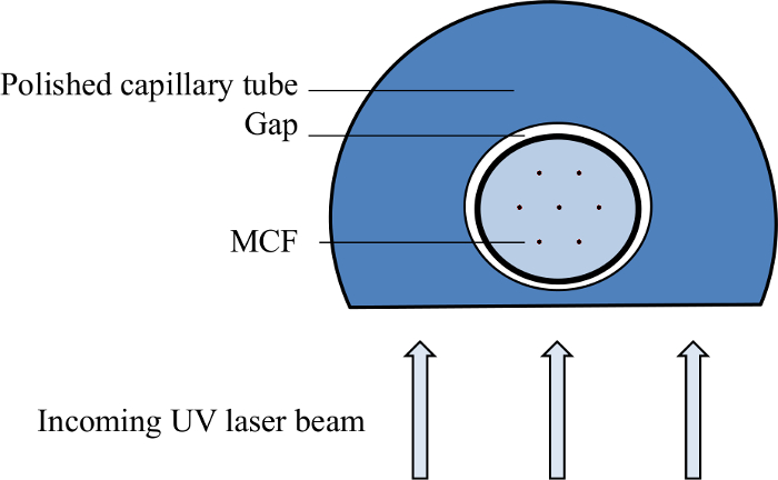
Figure 1. Diagram of polished capillary tube as used in FBG production. The MCF is placed inside the capillary tube. The gap between the two should be small but allow for small variations in diameter. The UV light which has passed through the phase mask then enters the system through the flat side of the capillary tube. Please click here to view a larger version of this figure.
Access restricted. Please log in or start a trial to view this content.
Protocol
1. Preparation of Polished Capillary Tubes (ANFF OptoFab)
- Obtain glass capillary tubes with inner diameter closely matched to fiber diameter. The closer in size, the better the performance, but ensure that a ±10 µm variation in capillary size is allowed for. Remove any protective coatings from the capillary tubes. Shave off coatings with a razor blade to remove them without damaging the tubes.
- Taper the capillary tubes to a smaller diameter if required. Use a computer-controlled automatic tapering machine if available.
- Secure a length of tubing with clamps at either end.
- Heat the capillary to melting point evenly around its diameter using a hot filament located between the clamps.
- Draw the capillary through the heating element with a constant tension until the desired length has been tapered to the smaller diameter.
- Cut the capillary tube into approximately equal lengths with a glass cutting tool. Ensure that these are at least 2 cm longer than the intended grating length but small enough to fit within the polishing equipment used. Note: For this experiment, a capillary length of 7 cm was used.
- Attach 8-10 of the capillary lengths to a glass puck using UV-curable glue. Install the puck onto a jig compatible with the lapping/polishing machine.
- Use the lapping/polishing machine to grind the exposed walls of the capillary tubes to a flat surface. CAUTION: Do not inhale loose grit. Note: The abrasive element is Al2O3 in a suspension of reverse-osmosis purified water.
- Use 25 µm grit until the remaining thickness of the capillary wall is approximately 70 µm. Use a micrometer to measure the displacement of the jig during grinding and hence the amount that has been removed.
- Switch to 5 µm grit and grind until the remaining thickness of the wall is approximately 50 µm.
- Use the lapping/polishing machine to polish the flattened surface for at least 3 hr with high-purity colloidal silica in alkaline dispersion (NaOH). Note: This restores the surface to optical quality. The silica can be prevented from solidifying by adding 1 part 0.004 M NaOH to 3 parts polishing solution.
- Separate the capillary tubes from the holding puck by soaking overnight in acetone.
- Examine the capillary tubes at both ends under a microscope with 10X magnification to check the wall thickness. Note: A good quality capillary will have a uniform thin (~ 50 µm) wall along its length.
2. Creation of Gratings
- Hydrogenate the MCF to increase photosensitivity.
- Place the fibers to be hydrogenated into a sealed airtight chamber. CAUTION: Ensure the chamber is securely bolted due to the presence of pressurized gases.
- Pump high purity H2 into the chamber. Use N2 gas as a booster to increase pressure.
- Leave the fibers inside the chamber for an extended period: 2 weeks at 300 bar and room temperature, or 3 days at 380 bar and 80 °C.
- Vent the gases from the chamber and remove the fibers. CAUTION: Ensure the room is well ventilated. Gases may act as asphyxiants, or fire risk in the case of H2.
- Keep the fibers in a freezer with temperature -70 °C or below until they are used. This slows the rate of hydrogen outgassing and preserves the increased photosensitivity.
- Strip the protective coating from the MCF. Strip MCFs the same size as SMFs with a standard SMF fiber stripper; otherwise shave off the coating with a razor blade. Remove the coating from the region where the grating is to be written, all the way to the end of the fiber.
- Insert the stripped end of the fiber into the capillary tube, and slide the tube along the fiber so that it covers the region to be inscribed.
- Put on UV-protective eyewear. Mount the fiber on the moving stage which holds the phase mask, with the flat side of the capillary tube angled towards the phase mask. Ensure the fiber is positioned within the interference pattern created by the mask, but not touching the mask itself as this may cause damage.
- Align the 244 nm laser so that the beam is perpendicular to the flat surface of the phase mask. Ensure that the fiber receives at least 90 mW of laser power.
- Expose a 4 cm length of the fiber to the UV interference pattern by moving the fiber and phase mask together with respect to the incoming beam at a rate of 0.25 mm/min.
- Remove the capillary tube from the fiber.
- Anneal the grating at 110 °C for 20 hr to stabilize the wavelength response. Note: This step is optional as the grating will stabilize by itself over the course of approximately three days, but annealing makes the process faster.
3. Analysis of Spectra
- Cleave both ends of the fiber. Use a fiber cleaver that allows the user to set both fiber diameter and tension to ensure a flat end surface.
- Illuminate one end of the fiber using a tunable laser with a central wavelength approximately matched to the Bragg wavelength.
- Connect a CCD camera to a PC with control software to display and record the fiber output. Image the fiber output with the CCD camera, using a microscope objective lens with 50X magnification in front of the camera to ensure that all cores cover multiple CCD pixels. Note: The following steps 3.4.1 – 3.5.5 are specific to the custom software used by the authors and represent only one method of capturing spectra.
- Select a circular region of pixels corresponding to each core by clicking on the centers of cores as they appear in the image in the control software. Enter the diameter of the cores in units of pixels in the 'Length or Diameter' field.
- Record the pixel values registered by the camera for the selected regions. Sum the values for all pixels covering a given core to quantify the total throughput at that wavelength.
- Connect the tunable laser to the control PC so that observations and data collection can be automated.
- Enter a wavelength approximately 5 nm below the Bragg wavelength in the 'Start Wavelength' field.
- Set the wavelength increment of the laser to 0.01 nm in the 'Scan - Step' field. Note: Set the delay between steps to at least 300 msec so that lasing is stable at each wavelength before measurements are recorded and the next wavelength step occurs.
- Enter a wavelength approximately 5 nm greater than the Bragg wavelength in the 'End Wavelength' field.
- Click the 'Automatic Scan' button to set the laser to the defined Start Wavelength and increase the wavelength by the chosen increment at regular time intervals.
- Record the intensity transmitted through each core for each wavelength step. Export the calculated values to a text file by enabling the 'Text File Save' option.
- Repeat the scan at least 3 times and average the data from all runs.
- Plot transmitted power versus wavelength for each core to generate a set of spectra.
- Compare the spectra of all cores to confirm whether they have the same suppression characteristics. Check that the central wavelength, depth and bandwidth of each grating match.
Access restricted. Please log in or start a trial to view this content.
Results
The effectiveness of this technique is best demonstrated by comparing the multicore fiber Bragg gratings (MCFBGs) that result from exposure with and without the capillary. Figure 2 shows the transmission characteristics of a 7-core MCF exposed using the standard method for SMFs, with individual core spectra represented by different colors. There is minimal overlap between the suppressed wavelengths, and core #5 has received weaker exposure resulting in a shallower notch. ...
Access restricted. Please log in or start a trial to view this content.
Discussion
Figures 2 and 3 together show that introducing the polished capillary tube (PCT) when writing gratings is sufficient to improve the uniformity of core spectra in the MCFBG. The rest of the inscription process is largely unchanged from established methods for creating SMF gratings and can be used with most existing FBG writing systems. Hence the preparation of PCTs as outlined in section 2 of the protocol is most critical for improving MCFBG uniformity. The best results are achieved with ...
Access restricted. Please log in or start a trial to view this content.
Disclosures
The authors declare that they have no competing financial interests.
Acknowledgements
The SAIL labs are funded through JBH's Australian Laureate Fellowship from the Australian Research Council.
This research was supported by the Australian Research Council Centre of Excellence for Ultrahigh bandwidth Devices for Optical Systems (project number CE110001018).
Experimental work was performed in part at the OptoFab node of the Australian National Fabrication Facility, utilizing NCRIS and NSW state government funding. Fiber hydrogenation services were provided by TE Connectivity in Redfern. SLS would like to acknowledge the Optics and Electronics Laboratory, Fujikura Ltd, Japan for providing the 7-core fiber used in this experiment.
Access restricted. Please log in or start a trial to view this content.
Materials
| Name | Company | Catalog Number | Comments |
|---|---|---|---|
| Multicore fiber | Fujikura Ltd. | 7 cores with diameter 5.5 µm, core separation 35 µm, hexagonally arranged within 125 µm cladding, NA = 0.177 | |
| Glass tapering machine | Vytran | GPX-3000 | |
| UV laser | Coherent | 300 FreD Innova | Frequency doubled 244 nm, at least 150 mW output. CAUTION: eye damage; wear appropriate goggles |
| Phase mask | Lasiris | PM-244-1069.50-50.8 | Custom component, 1069.50 nm grating period, 5.08 mm thickness |
| Capillary tubes | Polymicro | TSP200794 | Inner diameter 200 µm, outer diameter 794 µm |
| Lapping machine | Logitech | PM5 | Combination grinder/polisher |
| UV-curable glue | Norland | NOA-61 | Cures rapidly, removable with acetone |
| Microgrit | Eminess | Al2O3: 25 µm and 5 µm particle size | |
| Polishing fluid | Eminess | ULTRA-SOL 500S | SF-500S-5, ULTRA-SOL 500S N/D, 5 GAL |
| Sodium hydroxide | 0.004 M | ||
| Fiber cleaver | Vytran | LDC-400 | |
| Tunable laser | JDS Uniphase | SWS15101 | |
| IR Camera | Xenics | XEVA-1429 | 320x256 pixel, 16 bit resolution |
| Oven | Thermoline Scientific | LDO-030N | For annealing at T = 110 °C |
| Hydrogen gas | BOC | For hydrogenating fiber. CAUTION: flammable, pressurised gas | |
| Nitrogen gas | BOC | Booster for hydrogenation. CAUTION: pressurised gas | |
| Acetone | |||
| Razor blades |
References
- Othonos, A. Fiber Bragg gratings. Rev. Sci. Instrum. 68 (12), 4309-4341 (1997).
- Bland-Hawthorn, J., Englund, M., Edvell, G. New approach to atmospheric OH suppression using an aperiodic fiber Bragg grating. Opt. Express. 12 (24), 5902-5909 (2004).
- Jovanovic, N., Guyon, O., Martinache, F., Schwab, C., Cvetojevic, N. How to inject light efficiently into single-mode fibers. Proc. SPIE. 9147, 91477P(2014).
- Bland-Hawthorn, J., et al. A complex multi-notch astronomical filter to suppress the bright infrared sky. Nat. Comm. 2, 581(2011).
- Leon-Saval, S. G., Argyros, A., Bland-Hawthorn, J. Photonic lanterns. Opt. Express. 18 (8), 8430-8439 (2010).
- Trinh, C. Q., et al. GNOSIS: the first instrument to use fiber Bragg gratings for OH suppression. Astron. J. 145 (2), 51(2013).
- Content, R., et al. PRAXIS: low thermal emission high efficiency OH suppressed fiber spectrograph. Proc. SPIE. 9151, 91514W(2014).
- Birks, T. A., Mangan, B. J., Dìez, A., Cruz, J. L., Murphy, D. F. Photonic lantern' spectral filters in multi-core fiber. Opt. Express. 20 (13), 13996-14008 (2012).
- Askins, C., et al. Inscription of fiber Bragg gratings in multicore fiber. BGPP. , JWA39(2007).
- Lindley, E., et al. Core-to-core uniformity improvement in multicore fiber Bragg gratings. Proc. SPIE. 9151, 91515F(2014).
- Lindley, E., et al. Demonstration of uniform multicore fiber Bragg gratings. Opt. Express. 22 (25), 31575-31581 (2014).
- Tomaru, S., Yasu, M., Kawachi, M., Edahiro, T. V. A. D. VAD single-mode fiber with 0.2 dB/km loss. Elec. Lett. 17 (2), 93-93 (1981).
Access restricted. Please log in or start a trial to view this content.
Reprints and Permissions
