In this manuscript, we demonstrate the preparation of a biohybrid hydrogel bioink containing graphene for use in peripheral tissue engineering. Using this 3D biohybrid material, the neural differentiation protocol of stem cells is performed. This can be an important step in bringing similar biomaterials to the clinic.
A subscription to JoVE is required to view this content. Sign in or start your free trial.
Method Article
Preparation and Characterization of Graphene-Based 3D Biohybrid Hydrogel Bioink for Peripheral Neuroengineering
In This Article
Summary
Abstract
Peripheral neuropathies can occur as a result of axonal damage, and occasionally due to demyelinating diseases. Peripheral nerve damage is a global problem that occurs in 1.5%-5% of emergency patients and may lead to significant job losses. Today, tissue engineering-based approaches, consisting of scaffolds, appropriate cell lines, and biosignals, have become more applicable with the development of three-dimensional (3D) bioprinting technologies. The combination of various hydrogel biomaterials with stem cells, exosomes, or bio-signaling molecules is frequently studied to overcome the existing problems in peripheral nerve regeneration. Accordingly, the production of injectable systems, such as hydrogels, or implantable conduit structures formed by various bioprinting methods has gained importance in peripheral neuro-engineering. Under normal conditions, stem cells are the regenerative cells of the body, and their number and functions do not decrease with time to protect their populations; these are not specialized cells but can differentiate upon appropriate stimulation in response to injury. The stem cell system is under the influence of its microenvironment, called the stem cell niche. In peripheral nerve injuries, especially in neurotmesis, this microenvironment cannot be fully rescued even after surgically binding severed nerve endings together. The composite biomaterials and combined cellular therapies approach increases the functionality and applicability of materials in terms of various properties such as biodegradability, biocompatibility, and processability. Accordingly, this study aims to demonstrate the preparation and use of graphene-based biohybrid hydrogel patterning and to examine the differentiation efficiency of stem cells into nerve cells, which can be an effective solution in nerve regeneration.
Introduction
The nervous system, which is the mechanism that bridges the internal structure of the organism and the environment, is divided into two parts: the central and peripheral nervous systems. Peripheral nerve damage is a global problem that constitutes 1.5%-5% of the patients who present to the emergency department and develops due to various traumas, leading to significant job loss1,2,3.
Today, cellular approaches to peripheral neuro-engineering are of great interest. Stem cells come first among the cells used in these approaches. Under normal conditions, stem cells are the regenerative cells of the body, and their number and functions do not decrease with time to protect their populations; these cells are specialized but can differentiate upon appropriate stimulation in response to injury4,5. According to the stem cell hypothesis, the stem cell system is under the influence of its microenvironment, called the stem cell niche. The preservation and differentiation of stem cells are impossible without the presence of their microenvironment6, which can be reconstituted via tissue engineering using cells and scaffolds7. Tissue engineering is a multidisciplinary field that includes both engineering and biology principles. Tissue engineering provides tools for the creation of artificial tissues that can replace living tissues and can be used in the regeneration of these tissues by removing the damaged tissues and providing functional tissues8. Tissue scaffolds, one of the three cornerstones of tissue engineering, are produced using different methods from natural and synthetic materials9. Three-dimensional (3D) printing is an emerging additive manufacturing technology that is widely used to replace or restore defective tissues via its simple but versatile production of complex shapes using various methods. Bioprinting is an additive manufacturing method that enables the coexistence of cells and biomaterials, called bioinks10. Considering the interaction of nerve cells with each other, studies have shifted to conductive biomaterial candidates such as graphene. Graphene nanoplates, which have properties such as flexible electronics, supercapacitors, batteries, optics, electrochemical sensors, and energy storage, are a preferred biomaterial in the field of tissue engineering11. Graphene has been used in studies where the proliferation and regeneration of damaged tissues and organs were performed12,13.
Tissue engineering consists of three basic building blocks: scaffold, cells, and biosignal molecules. There are deficiencies in the studies on peripheral nerve damage in terms of providing these three structures completely. Various problems have been encountered in the biomaterials produced and used in the studies, such as them containing only stem cells or biosignal molecules, the lack of a bioactive molecule that will enable stem cell differentiation, the lack of biocompatibility of the biomaterial used, and the low effect on the proliferation of cells in the tissue niche, and, thus, nerve conduction not being fully realized2,13,14,15,16. This requires the optimization of nerve regeneration, reducing muscle atrophy17,18, and creating necessary homing19 with growth factors against such problems.At this point, the characterization and analysis of the neuro-activity of a surgical biomaterial prototype, to be transferred to the clinic, are very important.
Accordingly, this methods study investigates the bioink hydrogel patterning with graphene nanoplates formed by a 3D bioprinter and its effectiveness on the neurogenic differentiation of the stem cells it contains. Also, the effects of graphene on neurosphere formation and differentiation are investigated.
Access restricted. Please log in or start a trial to view this content.
Protocol
1. Culturing of Wharton's jelly mesenchymal stem cells
- Take the Wharton's jelly mesenchymal stem cells (WJ-MSCs, from ATCC) out of a −80 °C freezer. Culture WJ-MSCs in DMEM-F12 medium containing 10% fetal calf serum (FBS), 1% Pen-Strep, and 1% L-glutamine in a sterile laminar flow at room temperature, as described in Yurie et al.20.
- Cryopreserve some of the cells at 1 x 10⁶ cells/mL with freezing medium containing 35% FBS, 55% DMEMF-12, and 10% dimethyl sulfoxide (DMSO). For this, count 1 x 10⁶ cells on a Thoma cell counting slide and add the freezing solution dropwise. Quickly transfer the slide to a liquid nitrogen container.
- When cultured cells are 80% confluent in the flask, pour out the medium and wash with 5 mL of PBS. Add 5 mL of 0.25% trypsin and 2.21 mM EDTA-4Na. Incubate in an incubator at 37 °C for 5 min.
- Add 10 mL of DMEM-F12 medium with 10% FBS to the cells removed from the incubator. Suspend it well, collect the medium, and transfer the medium to a centrifuge tube.
- Centrifuge at a rotational speed of 101 x g for 5 min at room temperature. Discard the supernatant and re-seed the cells in new flasks with fresh nutrient medium containing 10% FBS.
NOTE: Commercial WJ-MSCs labeled with the GFP gene by the transduction method can be used to better visualize the biomaterial-cell interactions to be produced21. The groups to be used in this method can be created as shown in Table 1.
| Created Groups | Reasons to create | Number of reps | ||
| 2D WJ-MSCs (2D-C) | 2D Control | x 5 | ||
| 2D WJ-MSCs & Graphene (2D-G) | Graphene toxic dose determination in 2D | x 5 reps to each of different concentrations | ||
| WJ-MSCs are included in bioinks (3D-B ) | 3D Control | x 3 | ||
| WJ-MSCs & 0.1% Graphene are included in bioinks (3D-G ) | 3D Graphene-Bioink Biohybrid Group | x 3 | ||
| WJ-MSCs are in spheroid form on the bioinks (3D-BS ) | 3D Control of Spheroid Form | x 3 | ||
| WJ-MSCs & 0.1% Graphene arein spheroid form on the bioinks (3D-GS group) | 3D Graphene-Bioink Biohybrid Group of Spheroid Form | x3 | ||
| 3D Bioink drop | It is produced for SEM and FTIR characterization analysis. | x5 | ||
| 3D Graphene drop | It is produced for SEM and FTIR characterization analysis. | x5 | ||
| 3D Bioink with GFP labeled WJ-MSCs & 0.1% | Observation of the movements of WJ-MsCs in the bioink containing the appropriate dose of graphene. | x3 | ||
Table 1. Groups in the method. All 2D and 3D groups in the method are included.
2. Graphene toxicity and 2D imaging
- Preparation of graphene concentrations and application to cells
NOTE: Raw graphene nanoparticles were purchased commercially (industrial graphene nanoplates type) and were also donated. The dimensions of the particles were 5-8 nm in thickness, 5 µm in diameter, and 120-150 m2/g in surface area.- Weigh the graphene to create a 1% solution (mg/mL). Make a stock solution by adding 10 mL of DMEMF-12 medium with 10% FBS to the weighed 100 µg of graphene nanoparticles and label this solution as stock solution. Sterilize in an autoclave at 121 °C under 1.5 atm pressure for 20 min.
NOTE: The sterile graphene mixture is stored in the refrigerator at 4 °C until use. It may not be suitable for long-term use (maximum 1 month). In these cases, the mixture must be reconstituted and sterilized. - Prepare a mixture of medium graphene at different concentrations to determine non-toxic doses. Set the initial dilutions as 1%, 0.1%, 0.01%, 0.001%, and 0.0001% graphene/media.
- Starting with the 1% stock solution, take 1 mL successively from each concentration and transfer it into a new tube. Add 9 mL of DMEMF-12 medium with 10% FBS to each tube, making five gradually diluted samples, and shake and vortex the solutions to get equal distribution. Use only 10 mL of DMEMF-12 medium with 10% FBS as control.
NOTE: The heavy flakes of graphene precipitate and, hence, need to be redistributed. - Seed the WJ-MSCs in 6-well plates with 2 mL of fresh medium containing 10% FBS at 5 x 10⁵ cells per well. Incubate for 1 day at 37 °C. Then, divide the plates into groups of equal and repeated wells. Do five repetitions for each concentration.
- Discard the medium and then replace the medium with graphene medium concentrations at 2 mL per well. Use only the medium for the control group. Incubate the plates at 37 °C for 24 h.
- Weigh the graphene to create a 1% solution (mg/mL). Make a stock solution by adding 10 mL of DMEMF-12 medium with 10% FBS to the weighed 100 µg of graphene nanoparticles and label this solution as stock solution. Sterilize in an autoclave at 121 °C under 1.5 atm pressure for 20 min.
- Determination of non-toxic concentrations of graphene with MTT
- Discard media with graphene after 24 h. Wash each well with PBS. Add fresh DMEMF-12 medium with 10% FBS at 2mL per well.
NOTE: It is important to wash with PBS following the application of graphene concentrations on the cell because graphene nanoparticles, which are not taken into the cell by endocytosis, are removed from the environment. This makes the MTT test more efficient. - Use the MTT (3-(4,5-dimethylthiazol-2-yl)-2,5-diphenyl-tetrazolium bromide) protocol to determine the IC50 value indicating 50% cell viability, as described in Kose et al.22 and in steps 2.2.3.-2.2.6.
- Firstly, weigh out 5 mg/mL of MTT salt and dissolve in PBS. Sterilize using a 0.45 µm filter. Wrap the MTT solution, made in a 15 mL centrifuge tube, with aluminum foil and store at 4 °C.
- Add 10 µL of MTT to all the wells and incubate the plate for 4 h at 37 °C. Observe the formation of formazan crystals at 10x magnification under the microscope after incubation.
- To dissolve the crystals formed in the cells, add 100 µL of DMSO to each well and mix by pipetting. Keep the plate in the dark at room temperature for 30 min. Insert the plate into the ELISA plate reader. Set a wavelength of 570 nm from the program for absorbance measurement and have it read the plate22.
NOTE: In addition, while graphene particles alone are read at 270 nm23, the read range of 570 nm24 here will be for reading cell viability only. - Perform statistical analysis on the obtained results using one-way ANOVA with Tukey's test in a statistical analysis program.
- Discard media with graphene after 24 h. Wash each well with PBS. Add fresh DMEMF-12 medium with 10% FBS at 2mL per well.
- Stitch imaging
- To examine the interaction of different graphene concentrations with cells, perform a time-lapse of the cells with the method called stitch imaging. This method creates a time-lapse image using image samples taken at regular intervals under the microscope.
- To do this, turn on the computer first. Turn on the time-lapse imaging incubator and set it to 37 °C. Place the MTT plate in the time-lapse incubator slot.
- Open the Stitch program on the computer. Specify the wells to be read in the system. Bring the reader to the first well and locate and focus the area at 10x magnification in white light. Start the program.
NOTE: It is a program for creating high-quality 4 rows x 5 columns multiple photo collages. The program combines photos taken one after the other in HD quality. When you press the system start button, the wells are automatically read, and it takes and stitches 4 rows x 5 columns multiple photos.
3. Graphene - Bioink biohybrid hydrogel production and WJ-MSCs differentiation
- Production of bioinks
NOTE: The lyophilized commercially available Alginate-Gelatin (3:5) powders are used as the basis of bioinks. The graphene bioink group (3D-G; 3D-GS) and the graphene-free control bioink group (3D-B; 3D-BS) are prepared with the same method (Table 1).- Use 50 mL conical tubes for the preparation. First, weigh 4.5 mg of alginate and 1.5 mg of gelatin and transfer to a centrifuge tube. Add DMEMF-12 medium containing 10% FBS to the mixture to a total volume of 50 mL. This is the control (C) group without graphene.
- Repeat weighing 4.5 mg of alginate and 1.5 mg of gelatin and transfer to a centrifuge tube. Then, take 50 µL of the prepared 0.1% graphene from step 2.1.3. and add it to the tube. Add DMEMF-12 with 10% FBS to a total volume of 50 mL.
- Mix the bioinks first by pipetting and then vortex. Sterilize in an autoclave at 121 °C under 1.5 atm pressure for 20 min. Alternatively, perform sterilization by microwaving until boiling point.
- After the mixtures are autoclaved, centrifuge at 280 x g for 2 min at room temperature to remove formed bubbles. Keep the bioinks at 37 °C until the cells are prepared.
- Addition of WJ-MSCs and 3D bioprinting
- For counting, wash the cells when there is 80% confluence with approximately 5 mL of PBS, and add 5 mL of 0.25% trypsin and 2.21 mM EDTA 4Na. Leave for 5 min at 37 °C.
- Add 10 mL of DMEM-F12 medium with 10% FBS to the cells after removing from the incubator. Suspend well, collect the medium, and transfer it to a centrifuge tube. Centrifuge at 101 x g for 5 min at room temperatures and then discard the supernatant.
- Leave approximately 250 µL of medium with the pellet. Redissolve the pellet in 1 mL of fresh medium. To 48 µL of medium, add 2 µL of cell suspension and 50 µL of trypan blue (0.4 g trypan blue/100 mL) in a conical tube (1.5 mL) for counting4. Pipette it well.
- Add approximately 10 mL of the prepared stained cell suspension to a Thoma cell counting chamber. Calculate the average number of cells falling into the squares on both sides of the light microscope.
Calculate the vitality percentage (%) = (counted viable cells/total cells counted) x 100
NOTE: The cell-bioink interaction is studied in two ways: (1) It can be printed by adding it into the bioinks (3D-B; 3D-G); (2) The cells are seeded on the bioinks after being pressed, and the cells form a spheroid (3D-BS; 3D-GS). - For the cell-bioink interaction, first create the bioink groups (Table 1). Group 1 includes 3D-B and 3D-G printed with bioink for bioprinting. Group 2 includes 3D-BS and 3D-GS bioinks on which spheroids were formed after bioprinting.
- Count the cells for group 1 so that there are approximately 1 x 10⁷ cells in 0.5 mL of medium. Add 4.5 mL of bioink to bring the total volume to 5 mL. Transfer this to the cartridges in the sterile cabinet with the help of syringes. Install the cartridges in the corresponding extruder section of the bioprinter.
- For the second group, take 5 mL from each of the bioink groups and transfer them to sterile cartridges with the help of an injector.
- Use the bioprinter with two coaxial printheads and the pneumatic-driven extrusion technology. Set the X/Y/Z resolution per microstep to 1.25 µm, the extrusion width to 400 µm, and the extrusion height to 200 µm. A 20 mm x 20 mm x 5 mm grid is one of the most used 3D models for 3D bioprinting work.
- Create the 3D models using open-source, web-based CAD programs. Before bioprinting, create simple 3D models with one of the open-source platforms (e.g., infill). The model can be linear (like the model used here), honeycomb, or grid-shaped.Export and download in .stl format after creating a 5 mm x 20 mm x 20 mm square.
- The bioprinter software uses .stl files and converts them to printable .gcode format using slicer modules. To get a printable grid shape, disable the outer shell in the slicer module. Wipe the device with 70% ethanol before operation and then sterilize by UV sterilization.
- For the bioprinting process, transfer the bioink groups to the cartridges with the help of an injector. Install the cartridges in the corresponding extruder section of the bioprinter.
- Set the average pressure of the 3D printer to 7.5 psi and the cartridge and bed temperature to 37 °C. Set the speed to 60% and carry out a standard 3D printing process.
NOTE: Planning the prepared models with spaces (like a linear model) allows cell culture to be done in the spaces after bioprinting. - Put the system in the home position during the writing phase. Position the axes (X, Y, Z) automatically, select the extruder, and set.Start the printing process. After the bioprinting process, take the sample and place it under a laminar flow cabinet.
- Spray the bioinks with 0.1 N CaCl2 solution after printing or add 1 mL of the solution with a pipette at room temperature. Wait for about 10-20 s and wash the printed patterns 2x with PBS containing Ca2+ and Mg2+.
- Add 2 mL of DMEMF-12 with 10% FBS medium on top of each of the cell-containing bioink groups. Incubate the plates at 37 °C with 5% CO2. Afterward, add 2 mL of suspension medium containing 1 x 10⁶ cells to each group for spheroid formation.
- Incubate the plates at 37 °C with 5% CO2. After 24 h incubation, observe the spheroid formation under an inverted microscope.
- WJ-MSCs differentiation to neuron-like cells
- Observe and photograph all batches of bioink after 24 h of incubation. Add 2 mL of neurogenic differentiation medium per well (except for the control group) and refresh every 2 days. Follow for 7 days to observe neural differentiation.
4. Graphene-Bioink biohybrid hydrogel characterization
NOTE: Time-lapse imaging, Fourier transform infrared spectroscopy (FT/IR), and scanning electron microscopy (SEM) analyses are performed for the characterization of graphene-bioink biohybrid hydrogel. The samples are created from 3D-B and 3D-G bioink groups by the drip method for FT/IR and SEM analysis.
- FT/IR analysis
NOTE: FT/IR is a chemical analytical method based on the mathematical Fourier transform, indispensable for material characterization. Use an FT/IR device based on 28 °C Michelson interferometer principles, with a halogen lamp, water-cooled mercury light source, signal aspect ratio of 4 cm−1, measured for 1 min, at 2,200 cm−1.- Prepare the FT/IR microscope and make sure the optics of the instrument are aligned. Calibrate the device.
- Since the sample is in a drop, take a piece of 1-2 mm thick hydrogel and place it with forceps on the sample part. Focus on the sample and raise it until close contact is made. Collect the sample spectrum by starting the process from the system.
- Scanning electron microscopy (SEM) analysis
NOTE: The surface morphology, internal structure, cell distribution, and bioink-cell interactions can be examined by SEM analysis in different dimensions.- Drop the hydrogel into 6-well plates containing 1 mL of CaCl2 crosslinker using the pipette tip droplet method (see Figure 1).
- Wash the plates 2x with approximately 1 mL of PBS to free the solution of salts. Then, put these drops into a falcon tube containing 5 mL of 5% paraformaldehyde with the help of forceps.
- Make thin sections from the drop bioinks with the help of a scalpel. Stick the samples on the sticky side on the metal plate. Insert into the coating device where the gold palladium, which passes into the plasma phase by replacing the air with argon gas, covers the sample.
- Put it in the electron microscope (SEM). Open the microscope program that the SEM is connected to. Perform the scaling and take images of different parts of the sample. For this protocol, 5 µm, 10 µm, and 200 µm scales were used. A total of 40 images were taken for the 3D-B and 3D-G groups.
- Time-lapse imaging
NOTE: During time-lapse imaging, not only bioink samples containing GFP gene transformed cells were used but also bioinks with spheroids are imaged for 16 h. Time-lapse imaging is performed to examine the effects of graphene on stem cells and to monitor cell interactions within the bioink.- Add commercially available 1 x 10⁷ GFP-labeled MSCs into 5 mL of bioink and bioprint as in step 3.2.11. Add 1 mL of crosslinker, hold for 20-30 s, and wash 2x with PBS.
- Turn on the time-lapse monitor and open the program on the computer. Set approximately 16 h in Time-Lapse mode and set the temperature to 37 °C. Press the Start button. Videos in the form of 40 s time-lapse video samples are recorded by the system.
- Focus the microscope at 10x magnification every 2 h. Also, visualize the spheroids created by following the same steps.
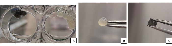
Figure 1: 3D-B and 3D-G bioink groups produced as drops for use in characterization. (A) Bioink samples (pre-characterization image) on a plate with a crosslinker. (B) 3D-B drop image of bioink. (C) 3D-G bioink drop image. The biomaterial to be characterized and the cells it contains can more easily go through processes such as gold plating, sampling, etc. Please click here to view a larger version of this figure.
5. Determination of neurogenic differentiation by immunostaining method
- Collect the spheroids, without interrupting sphere forms, and reseed into new plates to restain with an easier method, instead of embedding in paraffin for tissue sectioning.
- Cover the 48-well plates with about 20 mL of pre-autoclaved 0.1% gelatin solution and keep in an incubator for at least 1 h. Pipette approximately 500 µL of prepared 0.1% gelatin into 48-well plates. Leave the gelatinous plates in the incubator for 10 min.
NOTE: This will allow the gelatin to swell slightly, covering the surface and creating a better environment for the collected spheroids to attach. - Collect the spheroids by pipetting, distribute the collected spheroids from the incubator into the wells of the 48-well plate, and add fresh medium. Then, incubate for 12-24 h.
NOTE: It is quite difficult to distribute the spheroids by counting. Collect the spheroids in a single tube and evenly distribute the total volume to the wells. For this study, each well contained approximately 4-6 spheroids.
NOTE: For 2D samples, pre-stain washing is sufficient, and no media replacement is required. - Remove the medium and slowly wash the cells with PBS as the spheroids will be at the top. Fix in 4% paraformaldehyde for 2 h.
- Wash the samples with PBS again and block with about 10 mL of 2% BSA and 0.1% TritonX for 30 min. Then, wash with PBS 3x.
- Dilute selected primer antibodies (N-cadherin-rabbit and β-III tubulin-mouse) at a 1:100 ratio with antibody diluent reagent solution. Add 100 µL of antibody solution to each of the samples and incubate overnight at 4 °C.
- Wash the samples 3x with PBS. Incubate with anti-mouse IgG-FTIC-rabbit for β-III tubulin and anti-mouse IgG-SC2781-goat secondary antibody for N-Cad diluted to 1:200 at room temperature for 30 min. Perform all operations in the dark.
NOTE: Whatever strain is used as the primary antibody (e.g., mouse) in double staining, a different strain (e.g., goat or rabbit) should be used for the secondary antibody. - Wash the secondary antibody with PBS 3x and then drip the DAPI solution (1:1) into each of the samples. Wait for 15-20 min. Perform immunofluorescence imaging.
Access restricted. Please log in or start a trial to view this content.
Results
Graphene toxicity and 2D imaging
Statistical analysis of the obtained MTT results was conducted with a one-way ANOVA with Tukey's test in statistical analysis software, and the graph obtained is shown in Figure 2. The graphene percentage compared to control showed a significant decrease only for the 0.001% graphene concentration (**p < 0.01).. There were no significant differences between the other groups and the control (p > 0.05). Therefore, the optimum graphene ...
Access restricted. Please log in or start a trial to view this content.
Discussion
The advantages of treatments applied with engineered 3D scaffolds over conventional 2D methods are becoming more and more noticeable every day. Stem cells used alone in these therapies or along with scaffolds produced from various biomaterials with low biocompatibility and biodegradability are usually inadequate in peripheral nerve regeneration. Wharton's jelly mesenchymal stem cells (WJ-MSCs) seem to be a suitable candidate cell line, especially considering the optimization of the protocols for acquisition, their prolif...
Access restricted. Please log in or start a trial to view this content.
Disclosures
The authors declare that there is no conflict of interest. The project was performed in collaboration with HD Bioink, developer of the 3D bioprinting technology.
Acknowledgements
The graphene used in this study was developed at Kirklareli University, Department of Mechanical Engineering. It was donated by Dr. Karabeyoğlu. The graphene toxicity test was financed by the project titled "Printing and Differentiation of Mesenchymal Stem Cells on 3D Bioprinters with Graphene Doped Bioinks" (Application No: 1139B411802273) completed within the scope of TÜBİTAK 2209-B-Industry-Oriented Undergraduate Thesis Support Program. The other part of the study was supported by the research fund provided by Yildiz Technical University Scientific Research Projects (TSA-2021-4713). Mesenchymal stem cells with GFP used in the time-lapse imaging stage were donated by Virostem Biotechnology. The authors thank Darıcı LAB and YTU The Cell Culture and Tissue Engineering LAB team for productive discussions.
Access restricted. Please log in or start a trial to view this content.
Materials
| Name | Company | Catalog Number | Comments |
|---|---|---|---|
Centrifugal | Hitachi | Used in cell culture and biomaterial step | |
| 0.1N CaCl2 | HD Bioink | Used for crosslinker | |
| 0.22 µm membrane filter | Aιsιmo | Used for sterilization | |
| 0.45 µm syringe filter | Aιsιmo | Used for sterilization | |
| 1.5mL conic tube | Eppendorfa | Used for bioink drop | |
| 15mL Falcon tube | Nest | Used in cell culture step | |
| 25 cm2 cell culture flasks (Falcon, TPP tissue culture flasks | Nest | Used for cell culture | |
| 3D Bioprinting | Axolotl Biosystems Bio A2 (Turkey) | Bioprinting Step | |
| 50 mL Falcon tube | Nest | Used in cell culture step | |
| 6/24/48/96 well plates (Falcon, TPP microplates) | Merck Millipore | Used in cell culture step | |
| 75 cm2 cell culture flasks (Falcon, TPP tissue culture flasks | Nest | Used for cell culture | |
| Anti mouse IgG-FTIC-rabbit | Santa Cruz Biotechnology | J1514 | Seconder antibody, used for dye |
| Anti mouse IgG-SC2781-goat | Santa Cruz Biotechnology | C3109 | Seconder antibody, used for dye |
| Au coating device EM ACE600 | Leica | for gold plating of biomaterial section before SEM imaging | |
| Autoclave | NUVE-OT 90L | Used for the sterilization process. | |
| Autoclave | NUVE-OT 90L | Used for the sterilization process. | |
| Cell Cultre Cabine | Hera Safe KS | Used for the cell culture process | |
| Dulbecco's Modified Eagle's Medium/Nutrient Mixture-F12 | Sigma | RNBJ7249 | Used as cell culture medium |
| FEI QUANTA 450 FEG ESEM SEM | Quanta | FEG 450 | for SEM |
| Fetal Bovine Serum-FBS | Capricorn | FBS-16A | It was used by adding to the cell culture medium. |
| Freezer -80°C | Panasonic | MDF-U5386S-PE | We were used to store cells and the resulting exosomes |
| Gelatine-Alginate bioink powder | HD Bioink | Used for produced bioink step | |
| GFP labelled-WJ-MSCs | Virostem | Used for imaging to cell-bioink interaction | |
| Graphene nanoplatelets (Graphene-IGP2) | Grafen Chemical Industries Co. | Used for production 3D-G bioink | |
| Immunofluorescence antibodies (N-CAD; β-III Tubulin) | Cell Signalling and Santa Cruz | Used for dye | |
| JASCO 6600 | Tetra | for FTIR | |
| MTT Assay | Sigma | Viability testing | |
| Penicilin/Streptomycin Solution | Capricorn | PB-S | It was added to the medium to prevent contamination in cell culture. |
| Thoma slide | Isolab | Used for counting the cell | |
| Time-Lapse Imaging System | Zeiss Axio.Observer.Z1 | Imaging | |
| Tripsin-EDTA | Multicell | The flask was used to remove the cells covering the surface. | |
| Vorteks | Biobase | For produced bioink step | |
| WJ-MSCs | ATCC | Used for the cell culture process |
References
- Kamasak, B., et al. Peripheral Nerve Injuries and Physiotherapy. Clinical Physiotherapy. 19, Vize Publishing, Istanbul. (2019).
- Yegiyants, S., Dayicioglu, D., Kardashian, G., Panthaki, Z. J. Traumatic peripheral nerve injury: A wartime review. Journal of Craniofacial Surgery. 21 (4), 998-1001 (2010).
- Mushtaq, S., et al. Frequency of peripheral nerve injury in trauma in emergency settings. Cureus. 13 (3), 14195(2021).
- Allahverdiyev, A. Basic Principles of Somatic and Stem Cell Culture Systems, 1st Edition. , Nobel Medicine Bookstore. Istanbul. (2018).
- Allahverdiyev, A. M., et al. Adipose tissue-derived mesenchymal stem cells as a new host cell in latent leishmaniasis. The American Journal of Tropical Medicine and Hygiene. 85 (3), 535-539 (2011).
- Schofield, R. The relationship between the spleen colony-forming cell and the hemopoietic stem cell. Blood Cells. 4 (1-2), 7-25 (1978).
- Goodman, S. R. Stem Cells and Regenerative Medicine (Chapter 13). Goodman's Medical Cell Biology, Fourth Edition. , Academic Press. 361-380 (2021).
- Kaya, T. I. Tissue engineering. International Journal of Medical Sciences. 1 (48), 165-169 (2018).
- Sensharma, P., Madhumathi, R. G., Jayant, R. D., Jaiswal, A. K. Biomaterials and cells for neural tissue engineering: Current choices. Materials Science and Engineering: C. 7, 1302-1315 (2017).
- Hölzl, K., et al. Bioink properties before, during, and after 3D bioprinting. Biofabrication. 8 (3), 032002(2016).
- Zheng, Y., et al. 2D nanomaterials for tissue engineering and regenerative nanomedicines: Recent advances and future challenges. Advanced Healthcare Materials. 10 (7), 2001743(2021).
- Shin, S. R. Graphene-based materials for tissue engineering. Advanced Drug Delivery Reviews. 105, 255-274 (2016).
- Chen, M., Qin, X., Zeng, G. Biodegradation of carbon nanotubes, graphene, and their derivatives. Trends in Biotechnology. 35 (9), 836-846 (2017).
- Chen, S., et al. PAM/GO/Gel/SA composite hydrogel conduit with bioactivity for repairing peripheral nerve injury. Journal of Biomedical Materials Research Part A. 107, 1273-1283 (2019).
- Chiriac, S., Facca, S., Diaconu, M., Gouzou, S., Liverneaux, P. Experience of using the bioresorbable copolyester poly(DL-lactide-ε-caprolactone) nerve conduit guide Neurolac™ for nerve repair in peripheral nerve defects: Report on a series of 28 lesions. Journal of Hand Surgery (European Volume). 37 (4), 342-349 (2011).
- Karaaltin, A. B., et al. Human olfactory stem cells for injured facial nerve reconstruction in a rat model). Head & Neck. 38, 2011-2020 (2016).
- Bingham, J. R., et al. Stem cell therapy to promote limb function recovery in peripheral nerve damage in a rat model. Annals of Medicine and Surgery. 41, 20-28 (2019).
- Zhuang, H., et al. Gelatin-methacrylamide gel loaded with microspheres to deliver GDNF in bilayer collagen conduit promoting sciatic nerve growth. International Journal of Nanomedicine. 11, 1383-1394 (2016).
- Scheib, J., Hoke, A. Advances in peripheral nerve regeneration. Nature Reviews: Neurology. 9 (12), 668-676 (2013).
- Yurie, H., et al. The efficacy of a scaffold-free bio 3D conduit developed from human fibroblasts on peripheral nerve regeneration in a rat sciatic nerve model. PLOS ONE. 12 (2), 0171448(2017).
- Guo, Y., et al. Assessment of the green florescence protein labeling method for tracking implanted mesenchymal stem cells. Cytotechnology. 64 (4), 391-401 (2012).
- Kose, C., Kacar, R., Zorba, A. P., Bagirova, M., Allahverdiyev, A. The effect of CO2 laser beam welded AISI 316L austenitic stainless steel on the viability of fibroblast cells, in vitro. Materials Science and Engineering: C. 60, 211-218 (2016).
- Liu, Y., et al. Bio-adenine-bridged molecular design approach toward non-covalent functionalized graphene by liquid-phase exfoliation. Journal of Materials Science. 55, 140-150 (2020).
- Rehman, S. Reduced graphene oxide incorporated GelMA hydrogel promotes angiogenesis for wound healing applications. International Journal of Nanomedicine. 14, 9603-9617 (2019).
- Bei, H. P., et al. Graphene-based nanocomposites for neural tissue engineering. Molecules. 24 (4), 658(2019).
- Othman, S. A., et al. Alginate-gelatin bioink for bioprinting of HeLa spheroids in alginate-gelatin hexagon-shaped scaffolds. Polymer Bulletin. 78, 6115-6135 (2021).
- Peng, X. L., Li, Y., Zhang, G., Zhang, F., Fan, X. Functionalization of graphene with nitrile groups by cycloaddition of tetracyanoethylene oxide. Journal of Nanomaterials. 2013, 841789(2013).
- Zorba Yildiz, A. P., et al. 3D therapeutic approaches for peripheral nerve damage. 9th International Molecular Biology and Biotechnology Congress Abstract Book. , E- ISBN: 978-605-70057-4-8 (2020).
- Liau, L. L., Ruszymah, B. H. I., Ng, M. H., Law, J. X. Characteristics and clinical applications of Wharton's jelly-derived mesenchymal stromal cells. Current Research in Translational Medicine. 68 (1), 5-16 (2020).
- Yoo, J., et al. Augmented peripheral nerve regeneration through elastic nerve guidance conduits prepared using a porous PLCL membrane with a 3D printed collagen hydrogel. Biomaterials Science. 22, 1-12 (2020).
- Jansen, K., Meek, M. F., vander Werff, J. F. A., van Wachem, P. B., van Luyn, M. J. A. Long-term regeneration of the rat sciatic nerve through a biodegradable poly (DL-lactide-Ɛ-caprolactone) nerve guide: Tissue reactions with a focus on collagen III/IV reformation. Journal of Biomedical Materials Research. 69 (2), 334-341 (2016).
- Pathre, P., et al. PTP1B regulates neurite extension mediated by cell-cell and cell-matrix adhesion molecules. Journal of Neuroscience Research. 15, 143-150 (2001).
- Qing, L., Chen, H., Tang, J., Jia, X. Exosomes and their microRNA cargo: New players in peripheral nerve regeneration. Neurorehabilitation and Neural Repair. 32 (9), 765-776 (2018).
Access restricted. Please log in or start a trial to view this content.
Reprints and Permissions
