Here we introduce the principle, structure, and instruction of the intelligent high-throughput antimicrobial sensitivity testing/phage screening system. Its application is illustrated by using Salmonella isolated from poultry in Shandong, China, as an example. The Lar index is calculated, and its significance in evaluating antimicrobial resistance is discussed comprehensively.
A subscription to JoVE is required to view this content. Sign in or start your free trial.
Method Article
Application of the Intelligent High-Throughput Antimicrobial Sensitivity Testing/Phage Screening System and Lar Index of Antimicrobial Resistance
In This Article
Summary
Abstract
To improve the efficiency of antimicrobial susceptibility testing (AST) and phage high-throughput screening for resistant bacteria and to reduce the detection cost, an intelligent high-throughput AST/phage screening system, including a 96-dot matrix inoculator, image acquisition converter, and corresponding software, was developed according to AST criteria and the breakpoints of resistance (R) formulated by the Clinical & Laboratory Standards Institute (CLSI). AST and statistics of minimum inhibitory concentration (MIC) distributions (from R/8 to 8R) of 1,500 Salmonella strains isolated from poultry in Shandong, China, against 10 antimicrobial agents were carried out by the intelligent high-throughput AST/phage screening system. The Lar index, meaning "less antibiosis, less resistance and residual until little antibiosis", was obtained by calculating the weighted average of each MIC and dividing by R. This approach improves accuracy in comparison with using the prevalence of resistance to characterize the antimicrobial resistance (AMR) degree of highly resistant strains. For the strains of Salmonella with high AMR, lytic phages were efficiently screened from the phage library by this system, and the lysis spectrum was computed and analyzed. The results showed that the intelligent high-throughput AST/phage screening system was operable, accurate, highly efficient, inexpensive, and easy to maintain. Combined with the Shandong veterinary antimicrobial resistance monitoring system, the system was suitable for scientific research and clinical detection related to AMR.
Introduction
As antimicrobial agents have been widely used to prevent bacterial infectious diseases, antimicrobial resistance (AMR) has become a global public health problem1. Combating AMR is the current main mission of monitoring AMR of epidemiological pathogens and synergistic therapy of sensitive antimicrobial agents and lytic bacteriophages2.
In vitro antimicrobial sensitivity testing (AST) is the mainstay for monitoring therapy and detecting the level of AMR. It is an important part of antimicrobial pharmacology and the critical basis for clinical medication. The Clinical and Laboratory Standards Institute (CLSI) of the United States and the European Committee on Antimicrobial Susceptibility Testing (EUCAST) have formulated and revised international criteria of AST and continuously modified and supplemented AST methods and the breakpoints to determine the MIC of one certain "organism-antimicrobial agent" combination as sensitive (S), resistant (R) or intermediate (I)3,4.
From the 1980s to the 1990s, automatic micro broth dilution instruments were rapidly developed and applied to clinical practice, with examples including Alfred 60AST, VITEK System, PHOENIXTM, and Cobasbact5,6,7. However, these instruments were expensive, required high-cost consumables, and their detection ranges were designed for clinical patient medication5,6,7. For these reasons, they are not suitable for veterinary clinical examination and detection of large quantities of highly resistant strains. In this study, an intelligent high-throughput AST/phage screening system, including a 96-dot matrix inoculator (Figure 1), image acquisition converter (Figure 2), and corresponding software8, was developed to conduct AST for a batch of bacteria strains against multiple antimicrobial agents at one time by the agar dilution method. Moreover, the system was also used to detect and analyze the lysis patterns of phages against antimicrobial-resistant bacteria9, and lytic phages were selected efficiently from the phage library. This system was found to be efficient, affordable, and easy to operate.
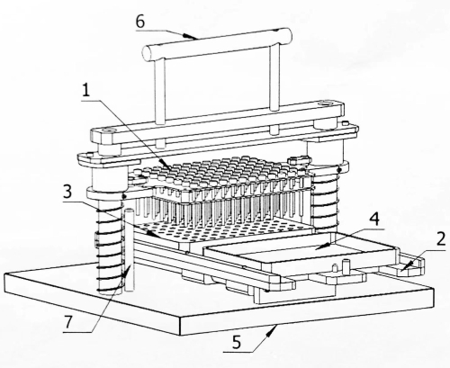
Figure 1: Structural diagram of the 96-dot matrix inoculator. 1: Inoculation pin plate; 2: Mobile carrier; 3: Seed block; 4: Incubated plate; 5: Base; 6: Operating handle; 7: Limit pin. Please click here to view a larger version of this figure.
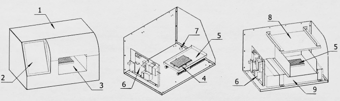
Figure 2: Structural diagram of the image acquisition converter. 1: Shell; 2: Display screen; 3: Image acquisition room; 4: Detection board base; 5: Detection board in and out of warehouse; 6: Control board; 7: Image acquisition conversion device; 8: Light source; 9: Image scanner. Please click here to view a larger version of this figure.
Access restricted. Please log in or start a trial to view this content.
Protocol
The Salmonella strains used in this study were collected from poultry in Shandong, China, after obtaining approval from the Biosafety Committee of the Institute of Animal Sciences and Veterinary Medicine, Shandong Academy of Agricultural Sciences, China.
1. Application of the intelligent high-throughput AST system8
- Inoculum preparation
- Incubate the quality control organism Escherichia coli and 93 Salmonella strains to be tested for AST on Mueller-Hinton agar (MHA) plates for 16-18 h at 37 °C3.
- Prepare the inoculum of each strain to match 0.5 McFarland turbidity standard based on the method specified in the CLSI standard3and then dilute 10 times.
- Place 200 µL of sterile normal saline into the horizontal 1st well (A1) of the 96-well plate as the negative control, two suspensions of quality control organism into the horizontal 2nd and 3rd wells (A2 and A3) as the positive control, and quality control, respectively. Add 200 µL of the diluted inoculum suspensions of each tested stain into the corresponding 93 wells in the 96-well seed block.
- Preparation of antimicrobial agar plate
- Set the concentration ranges of different antibacterial agents tested according to the calculation range of the Lar index (from 0.125R to 8R). The concentrations range from the quality control range or 0.0625R (subject to the lower range) to 8R.
NOTE: If the Lar index is not calculated, the range of antibiotic concentrations can be set according to the needs of AST. - Execute a log2 doubling dilution scheme for antibiotic solution beginning with a suitable stock concentration based on the agar dilution method specified in the CLSI standard3.
- Sterilize 50 mL glass bottles containing 18 mL of Mueller-Hinton agar media. Add 2 mL of the appropriate dilutions of the antimicrobial solution to 18 mL of molten media cooled to 45-50 °C, mix thoroughly, and pour into the plates in the biosafety cabinet.
- Allow the agar to solidify at room temperature (RT), leave a gap under the lid of incubated plates and blow to dry the agar surface before inoculating.
- Label the types of antimicrobial agents and concentrations on the reverse side of the incubated plates. Arrange the multiple incubated plates of each antimicrobial agent in a stack in log2-doubling dilution order.
- Prepare two drug-free agar plates as the controls for each antimicrobial agent.
- Set the concentration ranges of different antibacterial agents tested according to the calculation range of the Lar index (from 0.125R to 8R). The concentrations range from the quality control range or 0.0625R (subject to the lower range) to 8R.
- Inoculation steps for 96-dot matrix inoculator
- Install the autoclaved inoculation pin plate on the support of a 96-dot matrix inoculator in the biosafety cabinet.
- Place the prepared seed block with tested strains and an agar incubated plate on the mobile carrier, with the same positioning angle for the two plates.
- Push the mobile carrier so the seed block is directly below the inoculation pin plate.
- Press the operating handle, move the inoculation pin plate down, and direct the 96 pins to the inocula in 96 wells of the seed block.
- Release the operating handle with control, then reset the inoculation pin plate under the action of the spring.
- Press the operating handle 2-3 times to stir each inoculum well and dip. Push and move the carrier plate so the incubated plate is directly below the inoculation pin plate.
- Press the operating handle, move the inoculation pin plate down, and stop for 1-2 s to make the inoculation pins contact the surface of the incubated plate fully.
- Release the operating handle. This completes one inoculation. Replace another incubated plate and continue the cycle until one group of antimicrobial agar plates is finished.
- Replace another inoculation pin plate and seed block, and inoculate another group of tested strains. Cycle until all inoculations are completed.
NOTE: Inoculate a control agar plate (no antimicrobial agent) first, then the plate in order of drug concentration from low to high, and a second control agar plate last to ensure no contamination or antimicrobial agent carry-over. The inoculating volume relies on the volume of the natural deposition of each pin of approximately 2 µL.
- Incubating the antimicrobial agar plates
- Incubate the inoculated antimicrobial agar plates at RT until the moisture in the inoculum spots is absorbed into the agar.
- Invert the plates and incubate them for 16-20 h at 37 °C for the tested strains to ensure that the uninhibited bacteria form colonies.
- Image acquisition and data statistics
- Double-click on 96-dot matrix AST image acquisition system to open the program.
- Click on Test Information in the taskbar. Click on New to create a new test task, and fill in the information according to the prompts, including the code, name, source, bacteria, number of strains, antibiotics, and gradient.
- Click on Data Collection > Photograph > Test item to select the new task created. Click on Antibiotics to select the name of the antibiotic, and click on Gradient to select the initial concentration of this antibiotic.
- Click on Connect to connect with the image acquisition converter.
- Place the corresponding incubated plates on the detection plate base with the missing angle at the right front for orientation and push into the image acquisition converter.
- Click on Collection to obtain the images. The antibiotic gradient will automatically jump to the next gradient. Place the next plate in turn and continue to click on Collection until the plates for this antibiotic have been collected.
- Click on Antibiotics, and select the next set of incubated plates. Click on Gradient to select the starting gradient and proceed to the next round of image collection.
- After completing all collections, click on Submit. The program will automatically recognize the number of white pixels formatted at each inoculation point in the images, determine if there is colony formation and convert the images into MIC values.
- Click on Query to obtain all MIC results of the strains against the tested antibiotics.
NOTE: The intelligent high throughput AST system is suitable for determining MICs of large batches of bacterial strains. The testing process, including preparation, inoculation, incubation, and result reading, takes 3 days. The types of antibiotics and MIC detection ranges can be set according to respective needs, and the main consumables can be reused.
- Calculation of the Lar index
- Determine the Lar index accurately with the formula:
 , where:
MICi: minimum inhibitory concentration.
The range of MIC distributions from MIC-3 to MIC3 represents serial twofold concentrations centered on R: 0.125R, 0.25R, 0.5R, R, 2R, 4R, and 8R.
 is 2i, and the range of i is -3 to 3.
R: the breakpoints of resistance of bacteria against antimicrobial agents standardized by CLSI.
f: the MIC frequency distribution.
NOTE: The general Lar index is the arithmetic mean of all Lar indices. After the Lar index is calculated, round off the final value to two significant digits after the decimal point.
- Determine the Lar index accurately with the formula:
2. Intelligent high-throughput phage screening system9
- Preparing the phage seed block and double-layer incubated plates containing bacteria.
- Use the double-layer agar method10 or liquid culture method11 for making different phages. Dilute to a suitable parallel concentration with a titer of 1 x 10⁴-5 pfu/mL, and add 200 µL of the phage inoculum into the 96-well seed block.
- Make double-layered plates with bacteria (10 mL of bottom agar media [agar 12 g/L] and 6 mL of upper semi-agar media [6 g/L] with 100 µL of bacteria [0.5 McFarland]) to be tested.
- Make a double-layer incubated plate for each strain to be tested. Leave a gap under the lid of the double-layered plate and blow to dry the agar surface in the biosafety cabinet.
- Screening test
- Place the prepared phage seed block and double-layer plate on the mobile carrier of the 96-dot matrix inoculator, and transfer all phage inocula to the semi-agar surface. Continue the cycles until all tested strains are completed.
- Let the inoculated double-layer plates remain at RT until the moisture in the inoculum spots is absorbed fully into the semi-agar.
- Invert the plates and incubate under suitable conditions for the tested strains for 4-6 h to ensure that clear lytic spots are formed.
- Analyzing data
- Obtain and save the image of the experimental result of each double-layer plate by the image acquisition converter (steps 1.5.4-1.5.6).
- Record the number and morphologies of the different shapes of spots into a spreadsheet based on the obtained images, and calculate the respective proportions of the different kinds of phages.
Access restricted. Please log in or start a trial to view this content.
Results
Following the protocol of the intelligent high-throughput AST system, its application was illustrated by Salmonella from poultry in Shandong, China, as an example.
The growth of Salmonella strains on agar plates with ampicillin (R of 32 µg/mL) at concentrations from 2 to 256 µg/mL determined by the image acquisition converter is shown in Figure 3. The horizontal 1st well A1 was the negative control and showed no colony growth; A2 and A...
Access restricted. Please log in or start a trial to view this content.
Discussion
The agar dilution method has been well-established and used widely. The principle of the high-throughput AST system was that of the agar dilution method. One of the critical steps within the protocol was the accurate high throughput transfer of 96 inocula at one time, which was performed multiple times in a row. To complete this critical step, the pins of the 96-dot matrix inoculator were uniform and very smooth. The natural deposition of each pin was a volume of approximately 2 µL, which aggregated into small dropl...
Access restricted. Please log in or start a trial to view this content.
Disclosures
Yuqing Liu et al. have filed Chinese patents for the 96-dot matrix inoculator and image acquisition converter and their applications (Patent number ZL 201610942866.3 and Patent number ZL 201910968255.X).
Acknowledgements
This work was supported by the National Key Research and Development Project (2019YFA0904003); Modern Agricultural Industrial System in Shandong Province (SDAIT-011-09); International Cooperation Platform Optimization Project (CXGC2023G15); Major Innovation tasks of agricultural Science and technology innovation project of Academy of Agricultural Sciences Shandong, China (CXGC2023G03).
Access restricted. Please log in or start a trial to view this content.
Materials
| Name | Company | Catalog Number | Comments |
|---|---|---|---|
| 96 well culture plate | Beijing lanjieke Technology Co., Ltd | 11510 | |
| 96-dot matrix AST image acquisition system | Institute of Animal Science and Veterinary Medicine, Shandong Academy of Agricultural Sciences | In-house software copyright | |
| 96-dot matrix inoculator | Institute of Animal Science and Veterinary Medicine, Shandong Academy of Agricultural Sciences | N/A | Patented product |
| Agar | Qingdao hi tech Industrial Park Haibo Biotechnology Co., Ltd | HB8274-1 | |
| Amikacin | Shanghai McLean Biochemical Technology Co., Ltd | A857053 | |
| Amoxicillin | Shanghai McLean Biochemical Technology Co., Ltd | A822839 | |
| Ampicillin | Shanghai McLean Biochemical Technology Co., Ltd | A830931 | |
| Analytical balance | Sartorius | BSA224S | |
| Automated calculation software for Lar index of AMR | Institute of Animal Science and Veterinary Medicine, Shandong Academy of Agricultural Sciences | In-house software copyright | |
| Bacteria Salmonella strains | Institute of Animal Science and Veterinary Medicine, Shandong Academy of Agricultural Sciences | N/A | Animal origin |
| Bacterial resistance Lar index certification management system V1.0 | Institute of Animal Science and Veterinary Medicine, Shandong Academy of Agricultural Sciences | In-house software copyright | |
| Ceftiofur | Shanghai McLean Biochemical Technology Co., Ltd | C873619 | |
| Ciprofloxacin | Shanghai McLean Biochemical Technology Co., Ltd | C824343 | |
| Clavulanic acid | Shanghai McLean Biochemical Technology Co., Ltd | C824181 | |
| Clean worktable | Suzhou purification equipment Co., Ltd | SW-CJ-2D | |
| Colistin sulfate | Shanghai McLean Biochemical Technology Co., Ltd | C805491 | |
| Culture plate | Institute of Animal Science and Veterinary Medicine, Shandong Academy of Agricultural Sciences | N/A | Patented product |
| Doxycycline | Shanghai McLean Biochemical Technology Co., Ltd | D832390 | |
| Enrofloxacin | Shanghai McLean Biochemical Technology Co., Ltd | E809130 | |
| Filter 0.22 μm | Millipore | SLGP033RB | |
| Florfenicol | Shanghai McLean Biochemical Technology Co., Ltd | F809685 | |
| Gentamicin | Shanghai McLean Biochemical Technology Co., Ltd | G810322 | |
| Glass bottle 50 mL | Xuzhou Qianxing Glass Technology Co., Ltd | QX-7 | |
| High-throughput resistance detection system V1.0 | Institute of Animal Science and Veterinary Medicine, Shandong Academy of Agricultural Sciences | In-house software copyright | |
| Image acquisition converter | Institute of Animal Science and Veterinary Medicine, Shandong Academy of Agricultural Sciences | N/A | Patented product |
| Meropenem | Shanghai McLean Biochemical Technology Co., Ltd | M861173 | |
| Mueller-Hinton agar | Qingdao hi tech Industrial Park Haibo Biotechnology Co., Ltd | HB6232 | |
| Petri dish 60 mm x 15 mm | Qingdao Jindian biochemical equipment Co., Ltd | 16021-1 | |
| Petri dish 90 mm x 15 mm | Qingdao Jindian biochemical equipment Co., Ltd | 16001-1 | |
| Salmonella phages | Institute of Animal Science and Veterinary Medicine, Shandong Academy of Agricultural Sciences | N/A | |
| Shaker incubator | Shanghai Minquan Instrument Co., Ltd | MQD-S2R | |
| Turbidimeter | Shanghai XingBai Biotechnology Co., Ltd | F-TC2015 | |
| Varms base type library system V1.0 | Institute of Animal Science and Veterinary Medicine, Shandong Academy of Agricultural Sciences | In-house software copyright | |
| Vertical high-pressure steam sterilizer | Shanghai Shen'an medical instrument factory | LDZX-75L | |
| Veterinary pathogen resistance testing management system | Institute of Animal Science and Veterinary Medicine, Shandong Academy of Agricultural Sciences | In-house software copyright | |
| Veterinary resistance cloud monitoring and phage control platform V1.0 | Institute of Animal Science and Veterinary Medicine, Shandong Academy of Agricultural Sciences | In-house software copyright |
References
- Ramanan, L., et al. Antimicrobial resistance-the need for global solutions. The Lancet Infectious Diseases. 13 (12), 1057-1098 (2013).
- Xiaonan, Z., Qing, Z., Thomas, S. P., Yuqing, L., Martha, R. J. C. inPhocus: Perspectives of the application of bacteriophages in poultry and aquaculture industries based on Varms in China. PHAGE: Therapy, Applications, and Research. 2 (2), 69-74 (2021).
- CLSI. Performance Standards for Antimicrobial Disk Susceptibility Tests. CLSI document M100. , M100 32nd edition, Clinical and Laboratory Standards Institute, Wayne, PA . (2022).
- Yuqing, L., et al. Antimicrobial Sensitivity Testing Standard of EUCAST. , China Standards Press, Beijing. (2017).
- Barnini, S., et al. A new rapid method for direct antimicrobial susceptibility testing of bacteria from positive blood cultures. BMC Microbiology. 16 (1), 185-192 (2016).
- Höring, S., Massarani, A. S., Löffler, B., Rödel, J. Rapid antimicrobial susceptibility testing in blood culture diagnostics performed by direct inoculation using the VITEK®-2 and BD PhoenixTM platforms. European Journal of Clinical Microbiology & Infectious Diseases. 38 (3), 471-478 (2019).
- Dupuis, G. Evaluation of the Cobasbact automated antimicrobial susceptibility testing system. European Journal of Clinical Microbiology & Infectious Diseases. 4 (2), 119-122 (1985).
- A system of bacterial antimicrobial resistance detection and its operation method. China Patent. , ZL 201610942866.3 (2019).
- A high throughput test plate for screening bacteriophage of zoonotic pathogens and its application. China Patent. , ZL 201910968255.X (2022).
- Adams, M. H. Bacteriophages. , Interscience Publishers, New York. (1959).
- Nair, A., Ghugare, G. S., Khairnar, K. An appraisal of bacteriophage isolation techniques from environment. Microbial Ecology. 83 (3), 519-535 (2022).
- Shandong veterinary antibiotic resistance system. , http://www.varms.cn (2023).
- Ming, H., et al. Comparison of the results of 96-dot agar dilution method and broth microdilution method. Chinese Journal of Antibiotics. 43 (6), 729-733 (2018).
- Laxminarayan, R., Klugman, K. P. Communicating trends in resistance using a drug resistance index. BMJ Open. 1 (2), e000135(2011).
- Chen, Y., et al. Assessing antibiotic therapy effectiveness against the major bacterial pathogens in a hospital using an integrated index. Future Microbiology. 12, 853-866 (2017).
- Ciccolini, M., Spoorenberg, V., Geerlings, S. E., Prins, J. M., Grundmann, H. Using an index-based approach to assess the population-level appropriateness of empirical antibiotic therapy. Journal of Antimicrobial Chemotherapy. 70 (1), 286-293 (2015).
- Yanbo, L., et al. Preliminary application of inoculation system for high-throughput drug susceptibility test. China Poultry. 42 (6), 52-57 (2020).
Access restricted. Please log in or start a trial to view this content.
Reprints and Permissions
