The proposed setup allows controlled mechanical ventilation and Magnetic Resonance imaging of 3D thorax movement in mice and rats. We have used this setup to study the pathophysiology underlying mechanical ventilation-induced respiratory muscle dysfunction.
Method Article
3D Cine Magnetic Resonance Imaging of Respiratory Motion in Mechanically Ventilated Mice and Rats
* These authors contributed equally
In This Article
Summary
Abstract
The pathophysiology of diaphragm dysfunction in mechanically ventilated patients has yet to be fully understood, and adequate animal models are required to accommodate further research. Mechanical ventilation settings, such as the level of positive end-expiratory pressure (PEEP), play a crucial role. The goal was to develop a method to image 3D thoracic movement during mechanical ventilation of mice and rats at different respiratory pressure settings. Rats (Wistar) and mice (C57BL/6) were anesthetized with a mix of ketamine, atropine, and dexmedetomidine. Anesthesia was maintained by continuous infusion through a peritoneal catheter. Next, a tracheostomy was performed to enable mechanical ventilation of the animals. Animals were placed in a 7T MR system while ventilated with an MR-compatible ventilator. 3D cine imaging of the thorax was conducted using a 3D gradient echo sequence with pseudo-spiral k-space filling. A navigator signal, generated by the slice selection rewinder gradient, was recorded every TR. Retrospective binning and reconstruction of the data in 12 respiratory cine time frames was performed using in-house developed software. We successfully visualized thoracic movement in 3D in both species during mechanical ventilation, enabling the investigation of changes in thorax geometry throughout the respiratory cycle at varying PEEP levels. We found that retrospective binning of respiratory frames was highly facilitated by the fixed respiration rate. The protocol presented here can be used to study cardiac and thoracic geometry and movement in mechanically ventilated mice and rats.
Introduction
Mechanical ventilation is the cornerstone of treatment for acute respiratory failure in the intensive care unit. Unfortunately, it can also cause injury. Ventilator-induced lung injury, ventilator-associated brain injury, and ventilator-induced diaphragm dysfunction are examples of iatrogenic complications associated with acute mechanical ventilation1,2,3. The pathophysiology underlying these mechanisms of injury remains poorly understood. Experimental work in animals has identified important mechanisms that underlie complications of mechanical ventilation, allowing for translation to clinical practice through the application of new ventilation strategies4. A recent example is the research on the impact of ventilator dyssynchronies on diaphragm function in porcine ARDS models5. Such research in mechanically ventilated animal models is vital to elucidate the mechanisms of injury, even with the current tendency to move away from animal testing. Studies on the effects of mechanical ventilation require an intact cardiopulmonary system and the ability to simulate pathophysiology commonly seen in the ICU4. Large animal models are used often because they mimic human physiology more closely than rodents and can be ventilated with machines that are used in the ICU4. The main drawbacks are the large cost associated with using large animals and the lack of genetically engineered large animal models to investigate molecular mechanisms of disease6,7. Therefore, experiments in mechanically ventilated rodents are unavoidable as long as alternatives, such as sophisticated tissue cultures or organ-on-a-chip models, are not available.
Various interventions that improved outcomes in animals did not translate to humans4,6, underlining the importance of understanding how commonly used animal models of mechanical ventilation differ from humans. The effects of ventilator settings on the respiratory system are determined by a plethora of factors that may be species-specific, such as tissue elastance, muscle tone, and variation in the response to commonly used anesthetics8,9,10,11. These differences may lead to contrasting effects on thorax and lung movement and geometry that may account for the disparity between humans and animals. Investigating the effect of ventilation settings on the geometry and movement of the cardiopulmonary system may elucidate differences between species and may aid in the translation of pathophysiological concepts derived from animal studies to the clinical setting. The technical advancement of motion-resolved cardiovascular magnetic resonance imaging has enabled imaging of the beating heart in rodent models, providing insights into shape, function, and pathophysiology in rodent models of cardiovascular disease12,13. These methods are underutilized to image the thorax and movement during the respiratory cycle in mechanically ventilated animals.
Here, we present a method to study thorax geometry and movements in mechanically ventilated rodents using 3D cine MRI. This allows for studying the acute effects of numerous ventilator settings or other interventions on thorax geometry and movement in mechanically ventilated rodents. We applied a novel pseudo-spiral, respiratory-gated 3D cine MRI acquisition for ventilated small animals13,14. In this initial study, we investigated the effects of positive-end-expiratory pressure (PEEP), but this method can also be used to study the effect of other interventions or respiratory settings, such as I: E ratio, tidal volume, and respiratory rate. This method will open up a range of possibilities for pre-clinical imaging of rodent models that require mechanical ventilation in the field of intensive care research and beyond.
Protocol
All procedures described were performed according to the European Union EC directive 86/609. The experiments were approved by the Animal Ethics Board of Amsterdam UMC, location VUmc and AMC. C57BL/N mice and Wistar rats were obtained from Charles River laboratories. Male and female mice aged 3-6 months with a weight of 25-32 g and male and female rats aged 3-6 months with a weight between 200-400 g were used for all experiments. Food and water were provided ad libitum. All animals were acclimatized for at least 1 week before the start of experiments.
1. Preparation of the setup
- Prepare the anesthesia medications following the dosages mentioned in step 2.
- Calibrate the mechanical ventilator by scrolling through the ventilator menu and clicking Setup > More Ventilator > Calib&Tests. Perform all four tests and calibrations listed there: Leak Test, Purge Tubing, Measure Deadspace, and Purge Tubing.
- Place the MR-compatible mechanical ventilator in the MR room and pull the cables connected to the MR-compatible ventilator through the bore of the MR machine. One can use a test lung (for example, a small balloon) to check the ventilation coming from the MR-compatible ventilator.
- Connect the MR-compatible mechanical ventilator to the compressor and a source of oxygen flow.
- Prepare a PEEP column by filling a 10 mL measuring column with water and marking the depth of the water in centimeters. Place the MR-compatible ventilator's expiratory tubing in the PEEP column. An overview of the setup is shown in Figure 1.
- Tape a respiratory cushion loosely to the MR cradle at the location where the thorax of the animal will be.
2. Anesthesia and the start of mechanical ventilation
- Start sedation of the animal (mouse or rat) by placing it in a gas chamber filled with 4% isoflurane in 100% O2.
- Weigh the animal to determine the dose of anesthesia. Inject the surgical site (laryngeal area) with 3 mg/kg bupivacaine and apply eye ointment in both eyes.
- Place the animal on a heating pad while spontaneously breathing 2%-4% of isoflurane in 100% oxygen through a nose cone. Ensure monitoring of heart rate, oxygen saturation and temperature by placing a pulse oximeter on one of the paws of the animal and inserting the rectal thermometer probe.
- Test for absence of reflexes before incision. Lift skin covering the larynx and trachea with surgical forceps and make an incision using bent scissors.
- Bluntly dissect the salivary glands and underlying musculature until the trachea is visible.
- Using bent, sharp forceps, dissect the dorsal side of the trachea and place forceps underneath the trachea to pull a nonabsorbable braided silk suture (size 6/0) around the trachea.
- Grab the trachea at a cartilage ring and open the trachea immediately under the ring using spring scissors.
- Cannulate the trachea with a 20G (mouse) or 14G (rat) Abbocath, cut at approximately 1-1.5 cm in length. Tie the suture around the cannulated trachea to ensure an airtight seal.
- Start the animal's ventilation with a tidal volume of 7 mL/kg, frequency of 150 BPM for mice and 80 BPM for rats, 2 cmH2O PEEP with 3% isoflurane in 100% oxygen.
- Perform an intraperitoneal injection of the induction dose of injection anesthesia (mouse: ketamine 126 mg/kg, dexmedetomidine 0.1 mg/kg, atropine 0.5 mg/kg; rat: ketamine 90 mg/kg, dexmedetomidine 0.25 mg/kg, atropine 0.05 mg/kg) and after 5 min, gradually decrease the isoflurane flow (3% to 0% in 10 min) to allow for a smooth transition from gas to injection anesthesia.
- Place 24G Abbocath intraperitoneally and connect to perfusor with the following rates mouse: ketamine 36 mg/kg/h, dexmedetomidine 0.02 mg/kg/h, atropine 0.075 mg/kg/h; rat: ketamine 30 mg/kg/h, dexmedetomidine 0.015 mg/kg/h, atropine 0.075 mg/kg/h. Start infusion.
NOTE: We performed a tracheostomy to ventilate the animals instead of oral intubation because this enabled us to place a suture around the trachea. This was required to prevent air leakage, which is crucial for maintaining sufficient PEEP.
3. MRI under mechanical ventilation
- Place the animal in the dedicated MR cradle in a supine position, and place the appropriate MR coil for mice or rats over it while keeping an eye on the tracheotomy tube.
- Stop and disconnect the mechanical ventilator used in 1.2 and the anesthesia pump and transport the animal to the MR room. Reconnect the animal to the MR-compatible ventilator and start ventilating with a tidal volume of 10 mL/kg and a frequency of 150 BPM for mice and 80 BPM for rats. The tidal volume is larger than with the ventilator used in 1.2 to recruit lung tissue that might have collapsed during transport.
- Reconnect the anesthesia pump at the aforementioned rates to maintain the depth of anesthesia. Depending on the MR system, place the anesthesia lines inside or outside the MR bore.
- Place the sensor of the saturation and heart rate monitor on the hind limb of the animal and insert the rectal thermometer probe. Connect the respiratory monitoring system to the respiratory cushion. Check all signals and ensure that the heart rate, oxygen saturation, and temperature are in the physiological range.
NOTE: Respiratory monitoring should indicate the respiratory frequency set on the MR-compatible ventilator and is only used to detect respiratory effort from the animal. In case of respiratory effort from the animal, the respiratory curve shows additional peaks. This requires the administration of an additional dose of anesthesia (1/3 of the initial induction dosage). - Place the animal in the MR scanner with the coil centered over the thorax and connect the radiofrequency cables to the coil. There is a separate coil and cradle to accommodate the size difference between mice and rats (rat coil and cradle have a larger diameter compared to the mouse coil). Immerse the expiratory tubing 6 cm into the water column, administering 6 cmH2O PEEP.
- Titrate the tidal volume to 7-9 mL/kg depending on the oxygen saturation (go for lowest tidal volume that is possible with a saturation of 100%).
4. Scan acquisition
NOTE: Table 1 provides an overview of the scan settings.
- Use vendor-specified methods to perform RF calibration and shimming.
- Acquire a SCOUT with five images in coronal and axial orientation and make sure that the full thorax is in the field of view (FOV). A SCOUT is a fast scan used for planning the other imaging planes and usually covers a larger field of view than the other images. If needed, readjust the position of the animal in the cradle and redo the SCOUT.
- Plan the 2D scans (see Table 1 and Figure 2) on the SCOUT images. Ensure the coronal and sagittal plane cover the complete thorax.
NOTE: The sagittal plane is placed on the top of the right hemidiaphragm to limit the portion of the heart inside the FOV. By acquiring the SCOUT at 6 cmH2O PEEP, we make sure that the diaphragm is imaged at the most caudal position. - Acquire the 2D scans at 6 cmH2O PEEP and immediately reconstruct the images to check the animal's positioning and ensure image quality (follow step 6). If needed, readjust the positioning of the FOV or the animal and redo the scans.
- Plan the 3D scan (Figure 2) by placing the FOV around the complete thorax and cover the 2D scans. Ensure that about 20% of the FOV in the slice direction is outside the animal to prevent fold-over artifacts.
NOTE: The 2D scans are added to the protocol because the acquisition time is shorter than for the 3D scans, making them suitable for quickly testing the effect of interventions. - Acquire the 3D scan with the required pseudo-spiral k-space sampling scheme (Figure 3), allowing for robust retrospective binning of data and visualization of respiratory motion14.
- Repeat the 2D and 3D scans at 3 and 0 cmH2O PEEP. The total scan time was 2.5 minutes per 2D scan and 15 minutes per 3D scan.
NOTE: In this case, we adapted PEEP during the experiments. We selected 0, 3, and 6 cmH2O PEEP because we know from experiments (previous research and ongoing studies) with long-term ventilated animals these PEEP levels result in relevant changes in the diaphragm and thorax geometry15. Additionally, we opted for using zero, a medium and a high level of PEEP in this work to show the effect of PEEP. Depending on the research question, other interventions are possible. For example, the effects of muscle relaxants or other medications on thorax geometry can be studied. The protocol allows us to study the within-subject effects of the intervention.
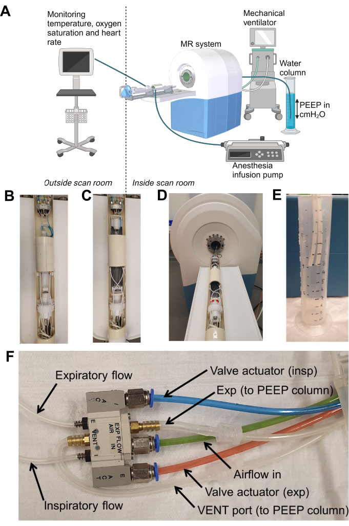
Figure 1: Overview of the set-up. (A) A schematic overview of the set-up, (B) the coil set-up for a mouse, (C) the coil set-up for a rat, with a larger bore than the mouse coil, (D) coil set-up with respect to the MR scanner, (E) the PEEP column with expiratory tubing placed at 3 cmH2O PEEP and (F) a close-up of the valve that regulates ventilation, indicating which tubes should be placed in the PEEP column. Please click here to view a larger version of this figure.
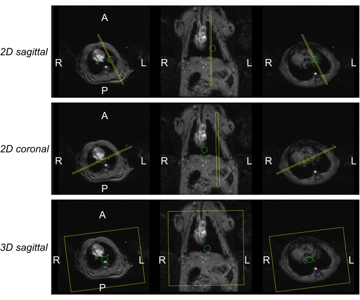
Figure 2: Planning of the MR Images for the 2D and 3D cines. Figure showing how the field of view was set for the 2D scans in sagittal and coronal orientation (upper and middle row) and 3D scans in sagittal orientation (bottom row). The left column represents one of the slices of the SCOUT in axial orientation at the heart level, the middle column shows a slice of the SCOUT in coronal orientation, and the right column shows a slice in axial orientation at the level of the liver. Please click here to view a larger version of this figure.
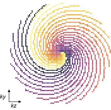
Figure 3: MR pseudo-spiral sampling pattern. The sampling pattern is in ky/kz phase encoding direction with matrix size 80 x 80 optimized for retrospective respiratory motion binning. Spirals are created by starting at the center of k-space and then turning out and in again, thereby repeating every spiral. The entire sampling pattern is performed with 25 repetitions to generate sufficient data within each respiratory frame. Each spiral has a different color. Please click here to view a larger version of this figure.
5. End of experiment
- After finishing all scans, remove the animal from the scanner. The animals cannot survive the experiment due to the tracheostomy. Euthanize mice with cervical dislocation and rats by exsanguination.
- Save all raw and reconstructed MR files.
| Scan type | Gradient Echo SCOUT | Gradient Echo 2D | Gradient Echo 3D |
| Orientation | Coronal and Sagittal | Coronal and Sagittal | Sagittal |
| k-Space sampling scheme | Cartesian | Cartesian | Pseudo-spiral |
| Number of slices | 10 | 1 | 80 |
| Slice thickness (mm) | 1 (Mouse) | 1 (Mouse) | 0.38 (Mouse) |
| 1 (Rat) | 1 (Rat) | 0.81 (Rat) | |
| Slice gap (mm) | 2 (Mouse) | 0 (Mouse) | 0 (Mouse) |
| 5 (Rat) | 0 (Rat) | 0 (Rat) | |
| Slice sampling* | 0.8 | 0.8 | 0.8 |
| FOV (read x phase x slice; mm) | 35 x 35 (Mouse) | 30 x 23 (Mouse) | 30 x 23 x 30 (Mouse) |
| 80 x 80 (Rat) | 65 x 49 (Rat) | 65 x 49 x 65 (Rat) | |
| Matrix size (freq x phase) | 256 x 192 | 256 x 192 | 211 x 80 x 80 |
| TR / TE (ms) | 45328 | 45330 | 45328 |
| Flip angle (°) | 15 | 15 | 10 |
| Number of repetitions | 80 | 70 | 25 |
| Respiratory triggering | No | Yes, retrospectively | Yes, retrospectively |
| Imaging time (min:s) | 2:02 | 2:23 | 16:00 |
| PEEP levels (cmH2O) | 6 | 6, 3, 0 | 6, 3, 0 |
Table 1: Acquisition parameters for all scans. * Slice sampling indicates which percentage of the slice selection pulse is used for imaging
6. Image reconstruction
- To perform image reconstruction, use the in-house developed software available on GitHub16. Perform these steps for all scans with a navigator requiring retrospective respiratory gating.
NOTE: It was previously described by Daal et al., but that work was focused on cardiac imaging13. Here, we describe a method for reconstructing respiratory gated images of the whole thorax. - Load the raw data file by clicking Load MRD. This visualizes the raw navigator signal and its spectrum in the top left panel. If the respiratory signal is not clearly visible, adapt the primary navigator in the tab Settings.
- In Heart/respiration filters, fill in the respiratory rate set on the MR-compatible mechanical ventilator and set the width to 15. The settings in the other boxes are not relevant to this type of reconstruction. Press Filter to apply the settings, which results in a gated navigator signal, as shown in Figure 4. Ensure the red signal in the box Respiration navigator and Respiration rate follow the blue, raw navigator signal.
- In Cine, select the Respiratory Movie and set the number of frames to 12 and the number of dynamics to 1. In the tab Geometry, turn on the PCA (level 8) and Ringing Filter. Press Sort k-space to apply the settings.
- In CS reco parameters, apply the following settings: WVxyz 0.0010, TVxyz 0.0000, LLRxyz 0.0050, TVcine 0.015, TVdyn 0.000. Press Reco Movies to start the reconstruction.
- Inspect the reconstruction in the bottom right panel by scrolling through the frames and (if applicable) slices. Export the reconstructed images by pressing Export DCM and/or Export GIF.
7. Image analysis
NOTE: Depending on the research question, several outcome parameters can be computed from the cine images. Here, we focus on parameters that quantify thorax geometry, lung volume, and excursion.
- Open an appropriate DICOM viewer, for example, the software mentioned in the Table of Materials and load a 2D cine by clicking on File > Open and selecting the 2D cine files. Identify the frame with the highest diaphragm position (end-expiratory frame). Select the frame and open it in the DICOM viewer.
- Measure the anterior-posterior and craniocaudal lung dimensions (Figure 5) in the sagittal 2D cine and the left-right dimension in the coronal-oriented 2D cine manually using the measure button in microdicom. Repeat these measurements for all PEEP levels or other interventions. These measurements can also be performed in one frame of the 3D cine, depending on the choice of scans.
- Load the 3D cine into the 3D image analysis program and place the image in the correct orientation by clicking Tools > Reorient Image. Fill in SPL as RAI Code. Select the end-expiratory frame by scrolling through the dynamics at Tools > Layer Inspector and then increase the Component number.
- Initialize the segmentation by manually contouring the middle part of the lungs in two slices for every orientation (Figure 6). Use the paintbrush mode and adjust the size of the brush if needed.
- Start the 3D segmentation by pressing Active Contour in the Main Toolbar. Ensure the red box (ROI) covers the complete thorax. Turn on Initialize with Current Segmentation and press Segment 3D.
- Select Thresholding as Presegmentation mode and use only an upper threshold by selecting the Rightmost Threshold Mode. Press Next. Then skip the step of adding bubbles by again pressing Next. Because the segmentation was already initialized at step 7.5, there is no need to add any bubbles.
- Start active contouring by pressing the Play button and pause it as soon as the segmentation reaches the edges of the lung. Scroll through the images to check the segmentation. Press Finish to finalize the segmentation.
- Press Update to visualize the 3D segmentation in the bottom left panel and inspect and rotate it.
- Save the segmentation as NiFTI by clicking Segmentation > Save Segmentation Image and STL Mesh File by clicking Segmentation > Export Segmentation Mesh.
- Write down the lung volume which can be found at Segmentation, Volume and Statistics.
- Register the images of the other respiratory states to the end-expiration dynamic using the script provided in Supplementary Coding File 1. Apply the computed transformations to the segmentation, resulting in a segmentation for every dynamic. Use these segmentations to compute outcome parameters, such as excursions in all directions.
Results
Using the protocol described in this study, we scanned a group of 8 healthy C57BL/6 WT mice and 8 Wistar WT rats successfully using a 7 Tesla MRI scanner. We were able to mechanically ventilate the animals at different levels of PEEP and monitor basic physiological parameters during scanning (Figure 7).
In Figure 5, an example of three 2D scans in the end-expiratory frame is shown of a mouse and a rat in sagittal orientation. As can be seen, PEEP introduces a caudal displacement of the diaphragm in both animals, but in mice, this is accompanied by a widening of the thorax as well, indicated by an increase in the anterior-posterior diameter.
These high-quality scans show that using this technique, we can measure the size of the different parts of the thorax and show the effects of various ventilatory settings on the movement of the thorax and the diaphragm. The short scan time allows for within-subjects comparison of the outcome parameters that one is interested in, reducing the required number of animals. Table 2 shows the outcome parameters of all animals.
Figure 8 shows the lung segmentations of the end-expiratory dynamic at three PEEP levels with the corresponding lung volume. As expected, increasing PEEP resulted in an increase in lung volume. The 3D cines are also displayed as a movie in Supplementary Video 1 and Supplementary Video 2.
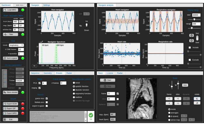
Figure 4: Screenshot of the software used to reconstruct the images with retrospective gating of the data. The gating of the data is based on the navigator signal. Please click here to view a larger version of this figure.
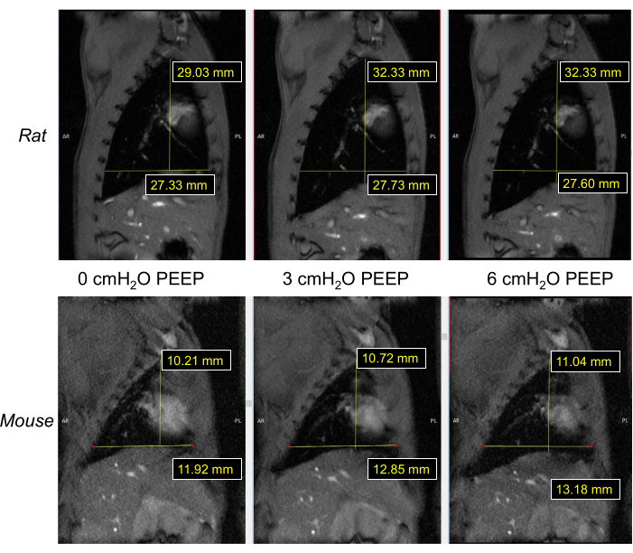
Figure 5: Representative results of 2D images in a rat and a mouse at three PEEP levels, with the anterior-posterior and cranio-caudal lung dimensions. Please click here to view a larger version of this figure.
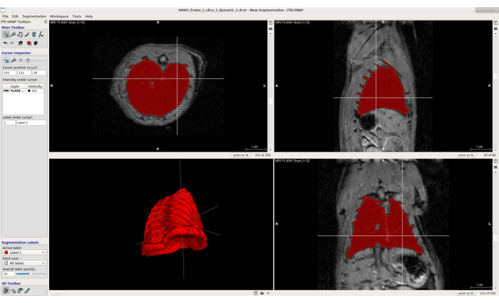
Figure 6: Screenshot of the software used to segment the lungs in the 3D cines. In the left-top panel, an axial view of the 3D cine is shown with the lung segmented in red. In the right-top panel a sagittal view is shown with the lung segmented in red. In the left bottom panel a 3D render of the segmented lung is shown. In the left-right panel, a coronal view is shown with the lung segmented in red. Please click here to view a larger version of this figure.
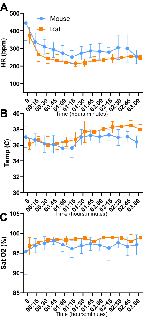
Figure 7: Vital parameters of the animals during the experiments. N = 8 mice (blue), N = 8 Rats (orange). Data is shown as mean with SD. Note the drop in heart rate when the animals enter a surgical plane of anesthesia. Please click here to view a larger version of this figure.
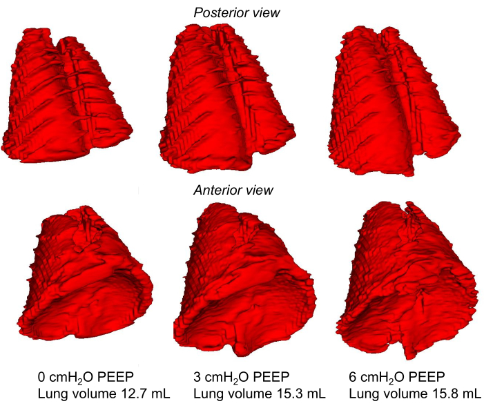
Figure 8: 3D Segmentation of the lungs at three PEEP levels with the corresponding lung volumes. Segmentation of a rat lung at PEEP 0 (left column), PEEP 3 (middle column), and PEEP 6 (right column). In the top row, the posterior side of the lungs is shown. In the middle row the anterior side of the lungs is shown. The volumes that are shown in the bottom row are measured within the 3D-rendered lungs that are visible in this figure. Please click here to view a larger version of this figure.
Supplementary Video 1: 3D cine of a mouse. Please click here to download this Video.
Supplementary Video 2: 3D cine of a rat. Please click here to download this Video.
Supplementary Coding File 1: Script to register the segmentations to other acquisitions. Please click here to download this File.
Discussion
This study shows that 3D MR imaging with retrospective gating allows to measure thorax movement in two animal models during mechanical ventilation. These techniques have the potential to be used in future research involving cardiac and thoracic imaging in mechanically ventilated mice and rats. We found that due to the fixed respiration frequency, retrospective binning was highly robust.
A critical step of the protocol is setting up the correct positioning of the animals within the MR coils. During scanning, it is not possible to reposition the animals. Additionally, maintaining normothermia is very important to ensure that measurements are made under physiological conditions, as anesthetics can cause hypothermia through peripheral vasodilation, and the radiofrequency pulses of this MRI protocol can cause hyperthermia17,18. In Figure 7, body temperature fluctuations can be seen during the short period around the transfer of the animals to the scanner (around the 1 h mark) in which no heat is applied from an external source. Another critical step is the titration of anesthesia, especially in mice. The plane of anesthesia where the mice do not exhibit respiratory effort but maintain stable vital parameters is narrow and requires careful monitoring of the respiratory signal and adjustment of anesthesia infusion rates. In rats, we did not face such issues within the range of sedation used. The image quality will be negatively impacted if there are respiratory efforts of the animal because of the retrospective reconstruction of the images based on the set respiratory frequency. It is possible to use a different anesthetic regimen, such as inhalation anesthesia with isoflurane or alternative injection anesthetics that cause more suppression of respiratory effort. The CWE-MRI-1 small animal ventilator used in this protocol is compatible with inhalation anesthetics19.
There are three critical steps for reproducing the MRI method proposed in this study. First, the same basic MRI sequence (i.e., 3D FLASH) must be used. Such a sequence is available on basically all MRI systems. Secondly, the k-space trajectory mentioned in this work (pseudo-spiral) may require a software patch that can execute user-defined k-space trajectories. We invite readers to reach out to the corresponding author if they wish to replicate the acquisition. There is experience in implementing this type of acquisition on systems from other vendors. Lastly, the reconstruction pipeline that we share as open-source software is vendor-neutral and, therefore, applicable to all preclinical systems.
We chose retrospective triggering and binning over prospective triggering for several reasons. Primarily, retrospective triggering and k-space data binning offer full flexibility in the number of reconstructed respiratory CINE frames, allowing us to optimize temporal resolution, spatial resolution, and signal-to-noise ratio. Additionally, prospective triggering introduces a dead time at the end of each respiratory cycle as the scanner waits for the next trigger, which can disrupt the steady state and result in an incomplete cycle. With mechanical ventilation, this dead time is minimal but still present.
The main limitation of this protocol is the inability to measure airway or esophageal pressures. To our knowledge, there are no MR-compatible lung or esophageal pressure sensors for small animals on the market. Another limitation is the lack of continuous blood pressure measurements within the MRI. The anesthetic protocol was based on prior institutional research. Atropine was added because of the high prevalence of bradycardia and hypotension observed previously. Although continuous blood pressure monitoring was not possible due to MR-environment constraints, hypertension is unlikely, as no tachycardia was observed (Figure 7). The monitoring employed in this protocol consisted of heart rate, oxygen saturation, temperature, and a respiratory signal based on movement of the thoracic wall. Using these measurements, an overview of the vital parameters of the animals can guide the administration of anesthesia but having a blood pressure read could prevent overdosing animals showing respiratory effort. No other MRI studies concerning the respiratory physiology of mechanically ventilated rodents have been published, but this method can be employed for a wide range of research questions outside of respiratory research. The reconstruction program mentioned in the manuscript (Retrospective) can also be used to reconstruct images throughout the cardiac cycle, thus allowing the researcher to acquire high-resolution images of the heart and vessels without motion artifacts. This protocol can be applied in every project that requires mechanical ventilation of rats or mice while scanning. One can, for example, consider studying the relation between mechanical ventilation settings and cardiac function. Other options include imaging animals with an open chest or after surgeries requiring mechanical ventilation.
Disclosures
Ruslan Garipov is an employee of MR Solutions Ltd., Guildford, United Kingdom.
Acknowledgements
This work was supported by ZonMW Grant 09120011910004 (GS, CO, LH) and NIH grant 5R01HL121500 (CO).
Materials
| Name | Company | Catalog Number | Comments |
|---|---|---|---|
| Equipment | |||
| 11 Plus Digital Dual Syringe Pump | Harvard apparatus (USA) | 229193-2 | dual syringe pump with programmable features for laboratories |
| AccuSens single and multi-channel signal conditioner | Opsens solutions inc. (Canada) | ACS-P4-N-62SC | Used with fiber optic temperature sensor to monitor body temperature |
| Fiber optic temperature sensor | Opsens solutions inc. (Canada) | OTP-M | |
| Mouse cradle | Équipment Vétérinaire Minerve (France) | ||
| Mousestat Jr. | Kent-scientific (USA) | MSTAT-JR | The MouseSTAT Jr. provides accurate pulse oximetry in both mice and rats. |
| MR Scanner | MR Solutions Lt. (United Kingdom) | MRS-7024 | |
| MR-compatible Monitoring & Gating System for Small animals | SA Instruments, Inc. (USA) | 1030 | RT Module (respiratory interface module) , ERT Control/ Gating Module, battery pack |
| MRI-1 compatible ventilator | CWE (USA) | 12-07000 | Mechanical ventilator suitable for ventilating small animals in magnetic resonance environments. It ventilates with a volume-controlled, flow x time based principle using pneumatic valves. |
| Multistation temperature control unit and High Flow PCA | Équipment Vétérinaire Minerve (France) | ||
| PEEP column | Repurposed fluid measuring column | ||
| Physiosuite Mechanical Ventilator | Kent-scientific (USA) | Mechanical ventilator suitable for ventilating small animals. It ventilates with a volume-controlled, pressure-regulated principle. | |
| Pulse Oximeter Paw Sensors, MRI-Compatible | Kent-scientific (USA) | SPO2-MSE-MRI | MRI-compatible paw sensor for Mousestat Jr. |
| Rat cradle | Équipment Vétérinaire Minerve (France) | ||
| RF coil, Mouse | MR Solutions Lt. (United Kingdom) | 38mm mouse volume RF coil for mouse body studies | |
| RF coil, Rat | MR Solutions Lt. (United Kingdom) | 65mm rat volume RF coil for rat body studies | |
| Surgical tools | |||
| Abbocath 14G, 20G, 22G, 24G | Abbocath | 14G, 20G, 22G for use as endotracheal tube, 24G for intraperitoneal infusion of anesthesia | |
| Ethilon 3-0 FD-1 suture with needle | Ethicon (USA) | 663H | |
| Forceps #55 | Dumont (Switzerland) | 55 | |
| Metzenbaum Scissors | Fine science tools (Germany) | 14017-14 | |
| Needle holder | Fine science tools (Germany) | 12005-15 | |
| Nonabsorbable braided silk suture 6/0 | Fine science tools (Germany) | 18020-60 | |
| Spring Scissors | Fine science tools (Germany) | 15033-09 | |
| Stevens tenotomy scissors | Fine science tools (Germany) | 14064-11 | |
| Suture Tying Forceps | Fine science tools (Germany) | 18025-10 | |
| Tape medipore | 3M (USA) | ||
| Medication | |||
| Atropine 0.25 mg/mL | |||
| Dexmedetomidine 0.5 mg/mL Dexdormitor | Orion pharma (Finland) | ||
| Duratears eye ointment | Alcon Nederland BV (Netherlands) | ||
| Isoflurane | AST pharma (France) | ||
| Ketamine 100 mg/mL Ketexx | Alfasan (Netherlands) | ||
| Vaseline petroleum jelly | Unilever (Netherlands) | ||
| Software | |||
| Elastix | Image Sciences Institute, UMC Utrecht (Netherlands) | ||
| Itksnap | University of Pennsylvania (USA) | ||
| Matlab 2019a | Wolfram Research Inc (USA) | ||
| Microdicom | Microdicom (Bulgaria) | ||
| Retropective | Amsterdam UMC (Netherlands) |
References
- Bassi, T., Taran, S., Girard, T. D., Robba, C., Goligher, E. C. Ventilator-associated brain injury: A new priority for research in mechanical ventilation. Am J Respir Crit Care Med. 209 (10), 1186-1188 (2024).
- Slutsky, A. S., Ranieri, V. M. Ventilator-induced lung injury. N Engl J Med. 369 (22), 2126-2136 (2013).
- Levine, S., et al. Rapid disuse atrophy of diaphragm fibers in mechanically ventilated humans. N Engl J Med. 358 (13), 1327-1335 (2008).
- Silva, P. L., Scharffenberg, M., Rocco, P. R. M. Understanding the mechanisms of ventilator-induced lung injury using animal models. Intensive Care Med Exp. 11 (1), 82(2023).
- Damiani, L. F., et al. Impact of reverse triggering dyssynchrony during lung-protective ventilation on diaphragm function: An experimental model. Am J Respir Crit Care Med. 205 (6), 663-673 (2022).
- Guillon, A., et al. Preclinical septic shock research: why we need an animal ICU. Ann Intensive Care. 9 (1), 66(2019).
- Larsson, L. Experimental animal models of muscle wasting in intensive care unit patients. Crit Care Med. 35 (9), S484-S487 (2007).
- Schwarte, L. A., Zuurbier, C. J., Ince, C. Mechanical ventilation of mice. Basic Res Cardiol. 95 (6), 510-520 (2000).
- Leith, D. E. Comparative mammalian respiratory mechanics. Am Rev Respir Dis. 128 (2 Pt 2), S77-S82 (1983).
- Vinegar, A., Sinnett, E. E., Leith, D. E. Dynamic mechanisms determine functional residual capacity in mice, Mus musculus. J Appl Physiol Respir Environ Exerc Physiol. 46 (5), 867-871 (1979).
- Oh, S. S., Narver, H. L. Mouse and rat anesthesia and analgesia. Curr Protoc. 4 (2), e995(2024).
- Li, H., et al. Technical aspects of small animal CMR imaging. Front Phys. 8, ARTN 183(2020).
- Daal, M. R. R., et al. Quantification of mouse heart left ventricular function, myocardial strain, and hemodynamic forces by cardiovascular magnetic resonance imaging. J Vis Exp. (171), e62595(2021).
- Gottwald, L. M., et al. Pseudo-spiral sampling and compressed sensing reconstruction provides flexibility of temporal resolution in accelerated aortic 4D flow MRI: A comparison with k-t principal component analysis. NMR Biomed. 33 (4), e4255(2020).
- Sudy, R., et al. Different contributions from lungs and chest wall to respiratory mechanics in mice, rats, and rabbits. J Appl Physiol (1985). 127 (1), 198-204 (2019).
- Strijkers, G. J. Retrospective-v9.7: Self-gated cine MRI reconstruction. , Available from: https://github.com/Moby1971/Retrospective-v9.8 (2023).
- Caro, A. C., Hankenson, F. C., Marx, J. O. Comparison of thermoregulatory devices used during anesthesia of C57BL/6 mice and correlations between body temperature and physiologic parameters. J Am Assoc Lab Anim Sci. 52 (5), 577-583 (2013).
- Tang, M., Yamamoto, T. Progress in Understanding Radiofrequency Heating and Burn Injuries for Safer MR Imaging. Magn Reson Med Sci. 22 (1), 7-25 (2023).
- Munting, L. P., et al. Influence of different isoflurane anesthesia protocols on murine cerebral hemodynamics measured with pseudo-continuous arterial spin labeling. NMR Biomed. 32 (8), e4105(2019).
Reprints and Permissions
