This protocol presents robot-assisted stereo electroencephalography (sEEG), a method for the stereotactic implantation of intracerebral electrodes used for invasive seizure monitoring in patients with refractory epilepsy. Techniques incorporating stereotactic robotic guidance for sEEG are safe and precise and may improve surgical efficiency, especially when implanting greater numbers of electrodes.
Method Article
Robotic-Guided Stereoelectroencephalography for Invasive Epilepsy Monitoring
In This Article
Summary
Abstract
Stereoelectroencephalography (sEEG) describes a precise method for the stereotactic implantation of intracerebral electrodes. Electrode implantation plans are made according to a localization hypothesis formulated using semiological, electrophysiological, anatomical, and imaging data. The placement of these electrodes is an invasive procedure commonly performed during pre-surgical investigation in patients with drug-resistant epilepsy who are undergoing work-up for potential surgical treatment. The technique has evolved with the inception of stereotactic robotic guidance systems, offering improved surgical efficiency while maintaining the precision and accuracy of classical frame-based stereotactic methods.
Here, we present our demonstration of robotic-guided sEEG, reviewing the principles of patient positioning, registration, and safe electrode placement. The goal of the protocol is to improve the efficiency of the technique, especially in circumstances where numerous electrodes are being implanted, while maintaining the precision, accuracy, and safety of classical frame-based techniques. This article will serve as a step-by-step guide for the general technique, as well as highlight a few key safety considerations and surgical nuances.
Introduction
Stereoelectroencephalography (sEEG) describes a precise method for the stereotactic implantation of intracerebral electrodes according to a localization hypothesis formulated using semiological, electrophysiological, anatomical, and imaging data1,2. The groundwork for this method derives from the previously published work of Talairach et al., who defined a 3-dimensional referential coordinate system of the brain using the anterior commissure and posterior commissure as internal landmarks, leading to the formation of a "Talairach Atlas"3. The Talairach frame was concomitantly designed to enable stereotactic placement of electrodes using 2-dimensional imaging such as X-ray and angiography. In subsequent years, there have been numerous innovations pertaining to 3-dimensional imaging modalities, stereotactic frame design, electrode placement and recording techniques, and intraoperative robotics that have increased the speed, precision, and workflow of sEEG electrode placement4. These innovations have helped surgeons to reliably and safely create trajectories in the brain that reach their targets and avoid critical structures, such as cortical blood vessels, as shown in the Szikla brain atlas (see Supplementary Figure 1 and video)5.
For nearly half of all refractory epilepsy patients, invasive recordings are commonly used to elucidate and define the epileptogenic zone, defined as the network of seizure organization and earliest propagation6,7. sEEG is a surgical method that permits network sampling of electrophysiological recordings from the brain, including deep structures such as the mesial temporal lobe, posterior orbitofrontal region, insula, and the cingulate gyrus, amongst other intracerebral locations1. The spatiotemporal resolution of sEEG data is useful in deciding the next steps toward surgical decision-making and can lead to successful surgical outcomes8. Moreover, the procedure benefits from a low-risk profile, with multiple large series reporting a low risk (0.04-0.08% per electrode) of hemorrhagic complications1,2,9,10. Importantly, the surgical workflow of the sEEG method has recently benefited from the introduction of modern-day robotic technologies, which we aim to illustrate here through a presentation of the stereotactic robotic-guided sEEG procedure.
Case Presentation:
Included is a presentation for one of the cases used in filming. The patient is a 46-year-old man with a history of drug-resistant epilepsy in the setting of left hemispheric cortical dysplasia associated with polymicrogyria. He had an extensive pre-surgical workup, which resulted in a pre-sEEG hypothesis of focal epilepsy despite the large hemispheric malformation. This hypothesis is the basis of the sEEG implantation plan.
sEEG Planning:
sEEG planning at our institution is done according to the French school of epileptology, using the Talairach atlas as the planning map. Importantly, according to the standardized nomenclature for this system, trajectory labels with an apostrophe denote the left side. For example, the A electrode targets the right amygdala, while the A' electrode targets the left amygdala. An orthogonal implantation strategy is employed, meaning that targets are identified, and then trajectories are selected that extend at an orthogonal angle laterally out to the skull. Some regions of interest, such as the insula, require oblique trajectories, rather than the standard orthogonal trajectories. Targets such as these carry a higher risk and should be performed by surgeons specifically trained in the method at experienced epilepsy centers. Importantly, the number of electrodes used must sample the anatomo-electro-clinical hypothesis formulated for each patient by the multidisciplinary epilepsy team. At our institution, this typically ranges from 12-20 electrodes.
The planning example (Supplementary Figure 2 and in the video) shows a typical left-sided implantation plan, including the targets, entry points, and labels. This is shown both in a table form and embedded into the Talairach atlas, which facilitates an anatomical understanding of the implantation plan.
Protocol
This study was conducted in accordance with the Cleveland Clinic's internal review board's guidelines on human subjects' research. IRB study number 09-847.
1. Plan electrode trajectories
- Use magnetic resonance (MR) imaging with contrast, along with CT venography, to carefully plan stereotactic trajectories that effectively sample the targets selected by the multidisciplinary team involved in the patient's pre-surgical planning.
- Identify targets and select trajectories that avoid critical structures, such as blood vessels.
NOTE: Trajectory planning is done before surgery, on the robotic planning station. The contrasted MRI should clearly distinguish white from gray matter, as the vast majority of targets selected are gray matter structures. The contrasted MRI shows arterial anatomy, while the CT venogram shows venous anatomy, so that the surgeon can avoid damaging vessels with their trajectories. - Ensure the operative team performs a final check on the day of surgery. Ensure the monitoring team takes the measurement of the robotic system to select the electrodes with appropriate length and contact spacings.
2. Attach the stereotactic frame to the patient's skull
- Next, affix the stereotactic frame to the patient's skull using appropriately sized pins. Ensure that the positioning of the frame does not interfere with planned electrode trajectories.
NOTE: The Leksell frame is a good option for head fixation, as it permits easy access to the face for facial recognition (in the event of laser registration), and to both sides of the head, facilitating either uni- or bilateral electrode placement1.
3. Co-register the Leksell frame to the patient's anatomy on imaging
- Attach co-registration fiducials either to the patient's anatomy or to the stereotactic frame. Obtain an intraoperative O-arm scan, which captures the patient's anatomy and the fiducials.
- Merge the intraoperative O-arm scan with the preoperative scans and use the robotic arm to register the locations of the fiducials. The software of the robotic arm will then co-register the location of the patient's anatomy with the planning images and the target trajectories.
NOTE: There are various options for stereotactic co-registration, including facial (laser-based) registration, or through the use of intra-operative CT imaging coupled with the use of skull-mounted or non-invasive fiducials attached to the frame itself (as in the latter case exemplified here, using a novel fiducial device that was recently validated11. The use of rigidly attached fiducials coupled with an intraoperative CT provides the highest accuracy and reliability, and fits well within the operative robotic-based workflow2,3.
4. Attach the robotic device to the Leksell head frame
- Once registration is complete, attach the robot to the stereotactic head frame using a starburst attachment.
5. Prep and drape
- Apply sterile prep and drapes to the patient's skin. Mark the borders for surgical exposure.
- Drape the robot arm. Subsequently, attach the distal portion of the robotic arm, featuring an instrument holder, through the drape.
6. Drill burr holes
- Drive the robotic arm into the position in keeping with the trajectory for each individual electrode as per the pre-operative stereotactic planning stage.
- Use axial movements of the robotic arm for precise movements along the electrode trajectory.
- With the robotic arm locked in position, drill the burr hole through a 2.55 mm guide tube securely fastened within the instrument holder.
- Use the guard on the drill as a guide stop to prevent plunging too deep through the bone.
- Use axial movements of the robotic arm to finely adjust the drilling depth, thus reducing time-consuming manipulation of the guard itself.
7. Open the dura
- Apply monopolar cautery to the dura using the monopolar cautery probe (see Table of Materials) through the 2.55 mm guide tube.
8. Implant the electrode-securing bolt
- Screw the cranial bolt (see Table of Materials) in place along the trajectory of the electrode.
- Apply an electrode-securing cap featuring an internal rubberized gasket, which minimizes the loss of any cerebrospinal fluid (CSF).
9. Place the electrode
- Position the robotic arm at 190 mm from the intended target.
- With the cap gently loosened on the bolt, use an intracranial obturator (see Table of Materials) to gently create the parenchymal trajectory. Gently palpate for any potential blood vessels along the length of the trajectory.
- Next, deliver an intracranial electrode through the 2.55 mm guide (which remains fixed on the robotic arm), along its trajectory, to the pre-measured target depth.
NOTE: These electrodes are pre-operatively marked at 190 mm, and therefore, care must be taken to ensure the robot is appropriately positioned at the same depth from the target (i.e., 190 mm) for safe, precise delivery of each electrode. - Finally, lock the cap to secure the electrode in position.
10. Secure the electrodes
- Secure each individual electrode at the intended target depth, using a bolt cap.
NOTE: Depending on the electrode design and manufacturer, it may be necessary to place the electrode solely relying on the implanted bolt rather than using the guide tube on the instrument holder.
11. Address bleeding
- Occasionally, bleeding at the site of the bolt is encountered. Address bleeding with gentle irrigation. Investigate copious bleeding further4,6.
12. Intraoperative recordings
- Once all electrodes have been placed, place and secure additional ground electrodes. Connect the entire setup to recording equipment and obtain an intraoperative recording.
- The quality of the intracranial recordings is interpreted by the Neurology and Neurosurgery teams to ensure adequate signals are being obtained from every electrode and to confirm that everything is working properly.
13. Wrap up
- Apply bacitracin ointment to each individual electrode/bolt site. Then, carefully (individually) hand-wrap each electrode/bolt using betadine-soaked gauze.
- Disconnect the robotic device from the Leksell frame.
- Gently remove the patient's head from the Leksell frame, taking care to protect the electrodes/bolts.
- Apply sterile head-dressing to safely secure the wires that are wrapped and secured.
Results
The use of stereotactic robotic guidance for sEEG has resulted in safe, precise, and time-efficient electrode placement. A representative example of sEEG electrode placement is illustrated in Figure 1. To examine the efficiency of this method, we compiled the surgical logs of all sEEG cases performed in 2023 (n=66). The time from patient entry into the room until incision (setup time), patient entry into the room until closure (room time), and the time from incision until closure (surgical time) were extracted. Importantly, the setup time encompasses anesthesia time (and all its inherent variability), in addition to Leksell G frame placement, imaging with the frame in place, and setup (including registration) of the robot. The average number of electrodes implanted was 19.2; the average room time was 279.6 minutes; and the average surgical time was 181.0 minutes. We divided the room and surgical time by the number of electrodes implanted in each case to calculate the 'room time per electrode' and 'surgical time per electrode.' The average room time per electrode was 14.9 minutes, and the average surgical time per electrode was 9.6 minutes. We found that both "per electrode" measures trended down as the count of implanted electrodes increased (Figure 2). The frame-mounted fiducials were used for 23/66 cases, in which intra-operative CT imaging (via the O-arm) was used for additional stereotactic registration. The setup time was increased in those cases with the frame-mounted fiducials and intra-operative CT workflow (118.6 min vs. 88.3 min), as well as the room time per electrode (18.7 min vs 12.9 min).

Figure 1: Representative sEEG Implantation X-ray: Intraoperative fluoroscopic X-ray imaging from an anteroposterior view. The image demonstrates linear placement of left-sided stereoelectroencephalography (sEEG) electrodes without any trajectory deformation. Please click here to view a larger version of this figure.
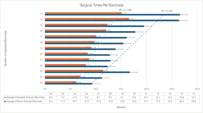
Figure 2: Operative Workflow Time for sEEG. The surgical time is calculated from incision to closure. The room time is calculated from room entry to closure. Each time is divided by the number of electrodes implanted in the case to give a "per electrode" time, and then averaged across all cases with a given number of electrodes implanted. Error bars demonstrate the standard error, and the R2 show the coefficient of determination for a simple linear model. Please click here to view a larger version of this figure.
Supplementary Figure 1: Midline and lateral brain images, highlighting the vascularization of the brain. This figure is reprinted from Szikla et al (1977)5 with permission. Please click here to download this File.
Supplementary Figure 2: Planning example. This figure is reprinted from the Cleveland Clinic Epilepsy Center, with permission. Please click here to download this File.
Discussion
The use of stereotactic frames to place intracerebral sEEG electrodes is well established in the literature, supporting this as a safe and precise method1,2,9,10,12. Moreover, there is a range of electrode numbers that may be used in sEEG, sometimes requiring more electrodes to investigate broader hypotheses of early seizure organization and propagation, especially in MR-negative (non-lesional) epilepsy7. The use of robotic guidance during sEEG placement has been shown to increase the speed and ease of electrode placement while maintaining the accuracy and precision of classical techniques. For example, prior series have shown a 40% reduction in implantation time per electrode when comparing the use of a robotic arm to classical frame-based techniques7. This benefit is particularly observed in cases where a large number of electrodes are placed. The set-up and take-down time of the robot remains constant, while the improved efficiency of robotic arm movements over manual frame adjustments is compounded as the number of trajectories increases. For example, in our series, when comparing the implantation of 13 electrodes to the implantation of 25 electrodes, the room time per electrode decreases from 15.1 minutes to 6.2 minutes (Figure 2). Although our data does not account for significant confounders, which may include variable anesthesia time and familiarity of nursing or neurosurgical trainees with the method, a simple linear regression comparing electrode count to surgical times accounts for >70% of the variance. This further demonstrates the value of stereotactic robotic-guidance in sEEG cases where greater numbers of electrodes are implanted.
Regarding critical steps of the procedure, it should be highlighted that co-registration of the frame to the patient's anatomy on imaging is imperative. This may be accomplished using facial (laser-based) registration, fiducials rigidly implanted into the patient's skull, or fiducial markers applied to the frame itself, as demonstrated in the video herein. In our experience, surgical times are lower when using the robotic system's embedded facial recognition (laser-based) co-registration technique, and additional intra-operative imaging for frame/fiducial registration is foregone. However, stereotactic accuracy when using rigidly-attached, frame-based fiducial markers affords a slightly more advantageous registration error (on the average order of 0.77 mm)11.
Another critical step in the sEEG implantation method relies on careful accuracy in drilling the burr holes through which the electrodes are placed. This is performed through the 2.55 mm guide tube firmly fixed to the robotic arm's instrument holder. Leveraging the axial movements of the robotic arm (and using the instrument holder itself as a guard device) can speed up the operative workflow here by reducing the time spent adjusting a separate guard device on the drill bit itself.
Another final critical step of the sEEG method is the placement of the electrode, which is conventionally performed following use of a fine obturator to prepare the brain parenchymal tract (while palpating for blood vessels to ensure safe passage). The electrode itself may be placed either through the robotic arm's instrument holder prior to the insertion through the sEEG bolt hardware, or simply (directly) through the implanted sEEG bolt. This workflow is largely contingent on the make, design, and manufacturer of the sEEG electrode technology used for the procedure. In both cases, care must be taken to measure the length of the electrode that will be placed within the cranium, such that it conforms with the preoperative plan.
Lastly, the most important risk of sEEG relates to the risk of hemorrhage, which is cited across large clinical series to be as low as 0.04% to 0.08% per electrode1,2,9,10. This may include epidural, subdural, or intracerebral hematoma formation. Hence, the patient is carefully examined post-operatively, and an immediate CT scan is obtained following the procedure to rule out the possibility of a complication. Of note, the risk of hemorrhage is mitigated by careful preoperative planning of electrode trajectories using two imaging modalities (contrast-enhanced CT and MR imaging), to ensure accurate sampling by stereotactic trajectories that avoid collision with vascular structures. Nevertheless, vigilance by the surgical team must be maintained during the procedure for any concerning signs of bleeding, which should be addressed promptly should they occur. Other notable risks of sEEG relate to infection and transient/permanent neurological deficit, amongst others.
Disclosures
The authors have no conflicts of interest to disclose.
Materials
| Name | Company | Catalog Number | Comments |
|---|---|---|---|
| Anchor Cranial Bolt Kit, LSB Style | Ad-Tech | LSB-BX-05 | One of many sizes available |
| Disposable Monopolar Cautery Probe | Kirwan | 30-6021 | 25.0 cm |
| GE OEC 9900 Elite Mobile C-Arm | GE | ge oec 9900 | |
| Intraoperative O-Arm CT | Medtronic | BI-700-00273 | |
| Intracranial Obturator (stylet) with Depth Stop | Dixi | ACS-770S-10 | Obturator for trajectory creation |
| ROSA One Brain: Robotic Neurosurgery | Zimmer Biomet | ROSAS00203 | |
| Spencer Probe Depth Electrode | Ad-Tech | SD06R-SP05X-000 | One of many sizes and configurations available |
References
- Serletis, D., Bulacio, J., Bingaman, W., Najm, I., González-Martínez, J. The stereotactic approach for mapping epileptic networks: a prospective study of 200 patients. J Neurosurg. 121 (5), 1239-1246 (2014).
- Cardinale, F., et al. Stereoelectroencephalography: retrospective analysis of 742 procedures in a single centre. Brain. 142 (9), 2688-2704 (2019).
- Talairach, J., David, M., Tournoux, P., Corredor, H., Kvasina, T. Atlas d'anatomie stéréotaxique. , Masson. Paris. (1957).
- Fomenko, A., Serletis, D. Robotic stereotaxy in cranial neurosurgery: a qualitative systematic review. Neurosurgery. 83 (4), 642-650 (2018).
- Szikla, G., Bouvier, G., Hori, T., Petrov, V. 1977 Angiography of the human brain cortex. , Springer-Verlag. Berlin. (1977).
- Talairach, J., Bancaud, J. "Stereotaxic approach to epilepsy: Methodology of Anatomo-functional stereotaxic investigations." Krayenbuhl, Maspes and Sweet (Eds). Prog Neurol Surg. 5, 297-354 (1973).
- Guenot, M., et al. Neurophysiological monitoring for epilepsy surgery: The Talairach SEEG method: Indications, results, complications and therapeutic applications in a series of 100 consecutive cases. Stereotact Funct Neurosurg. 77 (1-4), 29-32 (2002).
- Bulacio, J. C., et al. Determinants of seizure outcome after resective surgery following stereoelectroencephalography. J Neurosurg. 136 (6), 1638-1646 (2021).
- Mullin, J. P., et al. A systematic review and meta-analysis of stereo-electroencephalography-related complications. Epilepsia. 57 (3), 386-401 (2016).
- Bourdillon, P., et al. Stereotactic electroencephalography is a safe procedure, including for insular implantations. World Neurosurg. 99, 353-361 (2017).
- Sharma, A., et al. Validation and safety profile of a novel, Noninvasive fiducial attachment for stereotactic robotic-guided stereoelectroencephalography: A case series. Operative Neurosurg (Hagerstown, Md). , (2024).
- Cardinale, F., et al. A new tool for touch-free patient registration for robot-assisted intracranial surgery: application accuracy from a phantom study and a retrospective surgical series. Neurosurg Focus. 42 (5), E8(2017).
Reprints and Permissions
