This protocol contains a thorough description of a step-by-step approach for a chronic cranial window and microvascular embolism mouse model optimized for in vivo two-photon microscopy imaging using fluorescent polystyrene microspheres.
Method Article
Microvascular Embolism Mouse Model for In Vivo Two-photon Microscopy Using Fluorescent Polystyrene Microspheres
In This Article
Summary
Abstract
Microvascular occlusions in the brain are relatively common but remain largely understudied. The event rate, long-term consequences, and potential clearing mechanisms are largely unknown. Current models used to study these events, such as photothrombosis and micro-emboli injection, each have their own advantages and limitations. This study developed a detailed protocol that combines the preparation of a chronic cranial window with the induction of cerebral microvascular embolisms via intra-arterial injection of microspheres in mice. This setup allows for long-term in vivo imaging of the micro-vasculature and micro-occlusions using two-photon microscopy. Microspheres are delivered through a catheter placed in the external carotid artery (ECA), which is permanently ligated. Importantly, the common carotid artery (CCA) and internal carotid artery (ICA) remain intact throughout and after the procedure, thereby minimizing disturbance to cerebral blood flow. To facilitate immediate in vivo imaging and prevent microsphere clustering or adhesion to pipette tips and the catheter, microspheres are suspended in a mixture of FITC-Dextran and 0.1% Tween 20. The injection technique was validated using post mortem in situ 3D imaging to determine the microspheres' distribution. This study further demonstrates its utility with an in vivo two-photon microscopy example. This approach provides a consistent and robust method for inducing and studying microvascular embolisms, enabling investigation of their impact and clearance dynamics using high-resolution in vivo imaging.
Introduction
An ischemic stroke due to embolism of a large cerebral artery is an acute and often devastating event1. Emboli may also occur in more distal vessels. As a result, silent brain infarcts (SBIs) may develop; as the name suggests, these remain asymptomatic, and are typically discovered incidentally during imaging for unrelated reasons2,3. SBIs are common and rank among the most frequently observed cerebrovascular conditions in autopsies of elderly individuals4,5. Epidemiological studies have shown a 20% prevalence in individuals without a history of stroke. SBIs contribute to cognitive dysfunction and dementia, increase overall mortality, and are a risk factor for future stroke6,7,8. The infarcts are typically only a few millimeters in diameter and are associated with occlusion of penetrating arteries with diameters of roughly 100 µm. These penetrators give rise to an extensive arteriolar and capillary bed. A small microthrombus passing through the penetrating arteries and lodging in the downstream microcirculation will likely remain undetectable on angiography9. Yet, many microthrombi may be released in atrial fibrillation, atherosclerotic plaques, and from other sources10,11,12,13,14. Besides microthrombi, other microparticles (MPs), including fat particles, cellular aggregates, and even microplastics, may cause microvascular embolisms. Several studies show the presence of plastic MP in the blood and the brain that are larger than the capillary diameter of 5 µm15,16.
Microvascular occlusions remain relatively understudied compared with acute stroke and SBI. Little is known about the event rate, long-term consequences, and possible clearing mechanisms. Yet, interest is rapidly increasing after the successful clinical introduction of mechanical thrombectomy in stroke, where microvascular embolisms may cause impaired microvascular reperfusion after apparently successful recanalization of the large culprit artery17. In addition, there is a surge in research on microplastics, which may partly have their effect through microvascular embolism18,19,20.
Microvascular occlusions in the mouse cortex can be studied by, among others, multi-photon microscopy, using a cranial window. The most commonly used models to study cerebral microvascular occlusions are the photothrombotic and the microsphere model. The photothrombotic model employs photosensitive dyes to induce embolisms in selected vessels (typically non-capillary vessels) via photoactivation. However, this model does not allow the study of embolisms over a longer period due to the activation of the fibrinolytic system, which dissolves the embolism21,22. Moreover, activation of the light-sensitive dye produces singlet oxygen species, causing endothelial and blood-brain barrier (BBB) damage23. For studies on endothelial and BBB function during cerebral embolisms, and the long-term effects on cerebral circulation and brain function, the microsphere model is therefore preferred. The microsphere injection model uses microspheres injected into the cerebral circulation to occlude the cerebral microvasculature9,24,25,26,27,28,29,30. The possible disadvantage of this model lies in the fact that it is not possible to predetermine the location of embolisms, in contrast to the photothrombotic method31,32. The advantage is that microspheres of well-defined diameters can be injected, thereby targeting (micro-) vessels of specific diameters33,34,35.
Over the years, multiple approaches for the injection of microspheres into the cerebral circulation of rodents have been developed. These protocols find consensus in accessing the carotid triangle, consisting of the common carotid artery (CCA), internal carotid artery (ICA), and external carotid artery (ECA) for intra-arterial microsphere injection. The method for intra-arterial microsphere injection varies between protocols in several ways. Firstly, studies used either a syringe9,26,27,29,33,34 or a catheter25,28,30,36. Secondly, there is a considerable variation in the number and size of injected microspheres. Microsphere diameters typically range between 10 and 50 µm, with the choice depending on the target vessel size. As a rule of thumb, the larger the microspheres, the lower the number one should inject, as there are fewer arterioles than capillaries25,26,30.
Achieving consistent intra-arterial microsphere injection remains challenging. In practice, large numbers of microspheres are injected, yet only a fraction reaches the cerebral circulation. This is especially problematic for studying the effects of lodged microspheres by in vivo two-photon microscopy imaging, as the success of this technique depends on the presence of microspheres in the outer layers of the mouse cortex within the view through the prepared cranial window. Choosing appropriate fluorescent dyes for microspheres is critical, as combining them with transgenic mouse models and intravascular staining can be challenging due to the intense fluorescence of the microspheres and overlapping emission spectra.
Microvascular occlusions are studied in rodent models, and synergistic effects of multiple microspheres have previously been demonstrated in ex vivo rodent brains9, as well as apparent extravasation of such particles, a process called angiophagy33,35,37,38. To enable their in vivo investigation, methods were developed for multi-photon microscopy in mice with cranial windows. The purpose of the current study is to develop and report a detailed protocol for intra-arterial injection of microspheres in mice that optimizes the study of their effects on the brain tissue and their fate. The main advantage of this protocol is its improved delivery efficiency, minimizing microsphere loss and increasing the likelihood of their presence in the middle cerebral artery (MCA) territory within the cranial window imaging area. The optimized microsphere injection protocol is evaluated using in vivo two-photon microscopy and post mortem in situ 3D imaging with a dedicated imaging cryo-microtome39.
Protocol
All procedures involving animals followed the Guide for the Care and Use of Laboratory Animals. The Central Committee on Animal Experiments of the Netherlands awarded full approval (AVD11400202316817).
NOTE: Male and female mice aged between 2 months and 1 year were used. Upon arrival, animals were acclimated for 7 days before any experimental procedure. The animals were housed with a maximum of 4 per cage, provided with food and water ad libitum, and maintained on a 12 h light-dark cycle. NG2-DsRed and TIE2-GFP mice were obtained (see Table of Materials for details) and bred in-house.
1.Cranial window implant
- Anesthesia and pre-surgical care
- Add 0.06 mg/mL Carprofen to the drinking water 1 day before the start of the cranial window surgery.
- Weigh the mouse and administer 5 mg/kg Carprofen and 2 mg/kg dexamethasone subcutaneously 30 min before surgery.
- Prepare the surgical area by positioning a heating pad with a feedback system on the stereotactic frame and covering it with a sterile cloth.
- Lay out all sterile surgical instruments on a second sterile cloth.
- Anesthetize the mouse in an induction chamber with 1 L/min air mixture (30% oxygen and 70% medical air) and 3-4% isoflurane, followed by maintaining anesthesia with 1.5-2% isoflurane using a facial mask.
- Secure the mouse in a stereotactic frame and insert the thermometer probe of the heating pad rectally using lubricant. Apply eye ointment to prevent drying and set the heating pad at 37 °C.
- Subcutaneously administer 1.5 mg/kg ropivacaine at the surgical incision line 5 min before surgery.
- Shave and clean the skin over the skull from the neck to just past the eyes with betadine using a cotton tip.
- Surgical preparation for headbar and window fixation
- Using sterile forceps and surgical scalpel, make an initial incision in the skin over the posterior skull. Extend the incision from the lambda suture forward along the midline to the frontal sutures just anterior to bregma (Figure 1A). Carefully retract and remove the skin to fully expose the temporalis muscles on both sides.
- Apply approximately 0.1 mL of 1% lidocaine to the skull to minimize bleeding.
- Remove the periosteum and scratch all regions of the skull where the head bar will be fixed using a surgical blade. Make the scratches perpendicular across the skull to ensure firm adhesion of the head bar.
- Clean any remaining blood with a cotton tip and dry the skull using compressed air.
- Head bar fixation
- Prepare a dental glue mixture in a cold (4 °C) ceramic container by adding 100 µL of monomer to 0.1 g of polymer and mixing. Add 1 drop of catalyst to the mixture to initiate rapid solidification of the glue.
- Apply the glue to the bottom of the head bar. Slightly tilt the head bar towards the left lateral side from the sagittal sinus and press onto the skull. Apply additional glue to the edges of the head bar to seal all openings. This ensures firm adhesion.
- Make a dental cement mixture by mixing 100 µL dental cement fluid with 0.1 g powder. Apply the cement to all sides of the head bar while preventing the cement from flowing onto the skull at the drilling area. Add an additional layer of dental cement on top of the head bar to form a well, enabling application of fluids onto the cranial window (Figure 1B).
- Let the dental glue and cement dry for at least 10 min.
- Confirm firm adhesion of the head bar by gently applying pressure on the skull where the craniotomy will be made. The head bar is properly adhered when the skull is not moving and no fluid appears between the dental cement and the skull.
- Craniotomy
- Attach the mouse to the imaging holder using the head bar or keep it in the stereotactic frame to firmly secure the head of the animal during the craniotomy.
- Mark the craniotomy drilling target (4 mm diameter) on the skull using a fine-point marker. Locate the MCA visible through the skull to ensure the cranial window is positioned optimally, covering as much of the MCA as possible. To confirm the correct size and placement of the drilling target, hold the cover glass above the marked area and adjust the drilling target size as needed.
- Start drilling in circles at the markings without putting pressure on the skull, to prevent the generation of heat (Figure 1C). Cool the skull by applying saline every 30 s. While cooling, clean and cool the drill head by submerging it in water, then drying it with a paper towel. Remove all bone dust regularly using compressed air. Confirm the craniotomy size by placing the cover glass on the skull and adjusting the drilling if necessary.
- Continue drilling in circles until the bone is adequately thinned. Cracks will appear in the drilling area once the skull is almost punctured. Ensure that the bone is sufficiently thinned by adding saline to soften the thinned skull and gently pressing the middle of the cranial bone within the drilling area. The drilling area is thin enough when the skull moves down evenly on all sides of the drilling area under gentle pressure. Continue drilling until this point is reached. Do not drill through the skull; this will risk damaging the dura mater and brain tissue. Keep the drilling area soaked in aCSF if the dura mater is damaged or bleeding occurs.
NOTE: Before removing the skull, ensure all bone dust is cleared from the drilling area. Residual bone particles on the dura can potentially initiate bone regrowth underneath the window. - Thoroughly clear all bone dust by using aCSF and compressed air. Apply aCSF to the drilled area until the skull is fully submerged. Using a 27-gauge (0.4 mm x 16 mm) or 30-gauge (0.3 mm x 13 mm) needle, carefully puncture the thinned skull horizontally (~180°), avoiding damage to the dura mater and brain. Gently push the bone upward until it detaches, applying minimal force. If the bone does not detach easily, continue drilling. Remove the detached skull with forceps, keeping the brain submerged in aCSF (Figure 1D).
- Flush the brain with aCSF, then place a sterile, absorbent porcine gelatin hemostatic sponge soaked in aCSF on the brain to control local bleeding for 2 min. Carefully remove the sponge, keeping the brain submerged in aCSF. Continue flushing with aCSF to ensure no bone dust or blood remains on the brain. If bleeding persists, place a fresh sterile, absorbent hemostatic sponge soaked in aCSF on the brain.
NOTE: Minor bleeding is common during bone removal. Ensure bleeding has stopped before placing the glass, as residual bleeding can reduce window clarity.
- Cover glass placement
- Absorb the aCSF covering the brain with a cotton tip, leaving only a thin layer remaining. Place the cover glass on the brain and gently press it into the skull opening using bent micro-forceps. Ensure the cover glass sits slightly below the skull level and is positioned parallel to the head bar.
NOTE: The glass should be firmly pressed against the brain to prevent cavity formation and preserve window quality. Keeping the cover glass parallel to the head bar ensures it is perpendicular to the microscope objective, improving image quality. - Attach the cover glass to the skull and head bar with epoxy glue, applying it to the sides while holding the glass firmly in place and parallel to the head bar.
- Seal all edges of the cover glass with glue to prevent brain exposure. Keep one drop of aCSF on the brain during application to stop glue from seeping under the window or contacting the dura mater (Figure 1E).
- Allow the glue to solidify for 5 min.
- Absorb the aCSF covering the brain with a cotton tip, leaving only a thin layer remaining. Place the cover glass on the brain and gently press it into the skull opening using bent micro-forceps. Ensure the cover glass sits slightly below the skull level and is positioned parallel to the head bar.
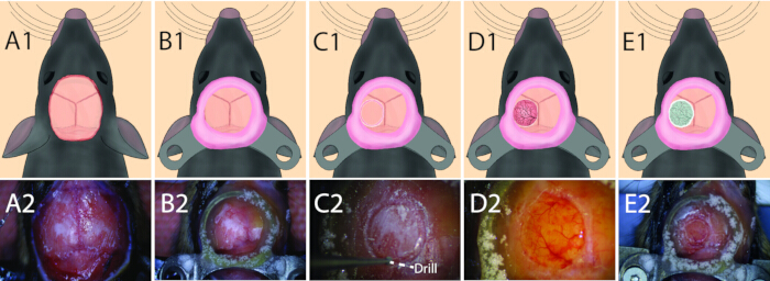
Figure 1: Overview of the craniotomy protocol. Detailed example pictures and schematic drawings of crucial steps during the craniotomy and headbar placement surgery. (A) Removal of the skin (step 2.2). (B) Attachment of the headbar (step 2.3). (C) Drilling of the 4 mm craniotomy (step 2.4.3). (D) Removal of the skull (step 1.4.5). (E) Placement of the cover glass (step 1.4.7). Please click here to view a larger version of this figure.
- post-surgical care
- Administer 5 mg/kg Carprofen subcutaneously.
- Transfer the animal to a 37 °C recovery cage for 30 min . Then return it to its home cage with 0.06 mg/mL Carprofen in the drinking water for up to 2 days post-surgery.
- Provide chow soaked in 0.06 mg/mL Carprofen until the animal returns to its pre-surgical weight.
- Allow the animal to recover for at least 7 days before performing the microvascular embolism model surgery.
2. Microvascular embolism mouse model
- Catheter assembly
- Insert the tip of a 20 cm long micro-catheter (ID 0.23114 OD 0.27432 mm) into a transparent catheter (ID 0.31 OD 0.64 mm) and seal the connection with epoxy glue and tape. Confirm the total length of the catheter is sufficient to hold at least 160 µL.
- Insert a 27-gauge luer-lock needle (0.1 mm x 16 mm) into the opposite end of the transparent catheter. Seal the end with epoxy glue and tape.
- Fill a 1 mL syringe with saline and connect it to the luer lock of the catheter needle. Flush with 0.7 mL of saline, ensuring no leaks or air bubbles remain.
- Fill the catheter with 80 µL of saline and mark the level reached in the catheter.
- Anesthesia and pre-surgical care
- Provide the mouse with drinking water containing 0.06 mg/mL Carprofen one day before the microvascular embolism surgery.
- Place a heating pad with a feedback system beneath a sterile cloth and set it to 37 °C.
- Place all sterile surgical instruments on a second sterile cloth.
- Weigh the mouse and administer 5 mg/kg Carprofen subcutaneously 30 min before the surgery.
- Anesthetize the mouse using 3-4% isoflurane in an induction chamber with a gas flow of 1 L/min consisting of 30% oxygen and 70% surgical air.
- Transfer the mouse to the surgical table and maintain anesthesia via a facial mask delivering 1.5-2% isoflurane at 1 L/min with 30% oxygen and 70% air.
- Insert a lubricated rectal temperature probe and apply eye ointment to prevent drying.
- Position a 2 mL syringe beneath the neck of the supine mouse to facilitate access to the surgical area.
- Gently secure the forepaws to the surgical table with tape.
- Shave the surgical area and apply betadine followed by lidocaine.
- Incision
- Verify the depth of anesthesia using a toe pinch.
- Make a midline incision of approximately 0.5 cm over the trachea below the mandible using surgical scalpel and dissecting forceps.
- Dissect the connective tissue superficial to the cervical fascia using micro-suture-tying forceps to expose the underlying sternohyoid muscles.
- Separate the left and right sternohyoid muscles by gently tearing the connective tissue between them. Retract the right omohyoid muscle caudal-laterally with a tissue hook. Ensure that the right carotid triangle, including the CCA, ICA, and ECA, is clearly visible.
- Surgical preparation of the CCA, ICA, ECA, and Posterior Parietal Artery (PPA)
NOTE: Avoid grabbing or pinching the vagus nerve; only move it gently to prevent adverse effects on the animal's health. Do not touch the trachea, as this can cause respiratory problems. Identify the occipital artery (OA), which branches from the ICA midway between the Y-shaped bifurcation of the ICA and the origin of the ECA, and the superior thyroid artery (TA), which branches from the medial side of the ECA. These arteries are fragile and should be handled with extreme care.- Remove any remaining fascia and adipose tissue surrounding the CCA.
- Carefully separate the CCA from the vagus nerve.
- Place two 4/0 1.5 threads around the CCA and tie them loosely. Ensure the knots do not impede CCA blood flow.
- Remove fascia and adipose tissue from the ICA and PPA. Temporarily ligate the PPA and all ICA side branches, including the OA, by tying a knot with a 4/0 1.5 thread.
- Remove fascia and adipose tissue from the ECA and TA. place two loose knots around the ECA and TA using 4/0 1.5 threads. Position the most distal thread as far away from the Y-shaped bifurcation as possible and use it to permanently ligate the ECA and TA. Leave the proximal knot untied.
- Microsphere solution preparation and catheter loading
NOTE: Prepare the FITC-Dextran/microsphere solution shortly before injection to minimize microsphere adhesion to the catheter.- Homogenize and sonicate the 10 µm microspheres (7.2 x 10⁶ microspheres/mL) to obtain a uniform suspension of individual particles.
- Prepare 140 µL of 25 mg/mL 70 kDa FITC-Dextran containing 0.1% Tween20, then add 20 µL of homogenized microspheres to obtain 160 µL of FITC-Dextran/Tween20/microsphere mixture containing 1.44 × 10⁵ microspheres.
- Briefly retract the syringe connected to the catheter to create an airlock.
- Immerse the catheter tip into the prepared FITC-Dextran/Tween20/microsphere mixture and slowly pull back the syringe until the mixture is in the catheter.
- Ensure no air bubbles are present in the catheter. If present, empty the mixture into a 0.5 mL container and repeat steps 2.5.3 and 2.5.4.
- Place the syringe with the loaded catheter in the syringe pump. Set the pump to 10 µL/min and run until a small drop of microsphere mixture appears at the catheter tip.
- Catheter insertion and microsphere injection
NOTE: Avoid injecting air bubbles into the vascular system, as this can cause severe adverse effects or death. Air bubbles may result from incorrect catheter loading or leaks in the tubing.- Place a vessel clip on the ICA and tighten one of the previously prepared proximal knots around the CCA (see step 2.4.3).
- Using micro-scissors, make a small diagonal incision in the ECA approximately 0.5 mm distal to the ligation thread. Ensure the incision size is slightly smaller than the catheter diameter.
- Absorb any blood with a sterile cloth or tissue, ensuring no blood continues to leak past the ligations and vessel clip.
NOTE: The vascular triangle must remain free of blood after the ECA incision. Residual blood can lead to clot formation, which may cause large cerebral ischemic events upon restoring carotid flow or block the ECA, preventing microsphere injection. - Briefly start the syringe pump to form a drop of microsphere mixture at the catheter tip, confirming that no air remains in the catheter tip.
- Open the ECA incision and insert the catheter using fine micro-forceps. Avoid touching other surfaces during insertion to prevent loss of the microsphere mixture or air entry into the catheter. If insertion fails or the catheter tip touches a surface, repeat step 2.6.4 before retrying.
- Secure the catheter in the ECA by tightening the proximal suture (see step 2.4.5.) around the ECA.
- Ensure that there is no leakage or air bubbles inside the vasculature by starting the syringe pump at 10 µL/min. If either is present, detach the catheter and return to step 2.6.4.
- If no leakage or air bubbles are detected, continue pumping at 10 µL/min to gradually increase the pressure in the catheter and vasculature until a visible enlargement of the artery is observed. To match the animal's arterial pressure, establish adequate pressure in the catheter and vasculature before reopening the ICA and CCA. When blood flow is restored in the CCA and ICA, some blood may enter the catheter, but it will subsequently be reinjected into the ICA. Visually confirm the injection of the microsphere mixture into the ECA and that the buildup of pressure is successful by observing the green FITC dye filling the arteries. If this is not observed, stop the syringe pump, remove the catheter, and repeat steps 2.6.4 to 2.6.8.
- Remove the vessel clip from the ICA, then increase the syringe pump flow rate to 20 µL/min. Confirm successful microsphere injection by verifying that the ICA distal to the PPA bifurcation is filled with FITC dye. If confirmed, proceed to step 2.6.11; if not, proceed to step 2.6.10.
- Stop the syringe pump and loosen the PPA ligation. Reposition the PPA ligation further distally from the ICA-PPA bifurcation, then tighten the ligation. Return to step 2.6.9.
- Remove the thread that ligated the CCA to enable the microsphere mixture to flow into the ICA.
- Troubleshooting in case of retrograde flow during injection of the microsphere mixture:
- If retrograde flow of the microsphere mixture into the CCA occurs, decrease the syringe pump flow to 10 µL/min.
- If retrograde flow continues, gently squeeze the ECA, ICA, and CCA using micro-forceps to ensure no obstruction of the flow is present due to a thrombus.
- Visually confirm that no air embolus is present inside the vasculature. An air embolus can be recognized as a transparent section within the vasculature.
- If an air embolus is present, stop the syringe pump and move the air embolus to the ECA by gently squeezing the artery using micro-forceps. Ligate the CCA and place a vessel clip on the ECA. Remove the catheter and air embolus and return to step 2.6.4.
- If no obstruction is present, but retrograde flow continues, close the CCA by using a vessel clip and return to step 2.6.10.
NOTE: Retrograde flow of the microsphere mixture into the CCA should not occur, as it may indicate inadequate ICA reopening, air embolism, or thrombus formation with potentially detrimental effects on the outcome of the experiment.
- Stop the microsphere injection by switching off the syringe pump once the mixture in the catheter reaches the 80 µL mark (see step 3.1.4). A total of 80 µL FITC-Dextran/Tween20 with 7.2 x 10⁴ microspheres is injected.
- Completion of the procedure
- Ligate the CCA using the remaining prepared knot (see step 2.4.3) and close the ICA with the vessel clip.
- Remove the catheter from the ECA while keeping the thread securing the catheter in the ECA in the same position.
- Permanently ligate the ECA by tightening the thread that had secured the catheter.
- Remove the vessel clip and threads around the CCA, ICA, and PPA to restore blood flow. Moisten the surgical area with a few drops of saline.
- Suture the skin with a reverse cutting 3/8 curved needle of 12 mm and a non-absorbable 3-0 (USP) silk suture.
- Postsurgical care
- Subcutaneously administer 5 mg/kg Carprofen.
- Transfer the animal to the recovery cage (~33 °C) for 30-60 min. Return the animal to its home cage once fully recovered.
- For the first 2 days, soak chow for 10 min in 0.06 mg/mL of Carprofen and provide it to the animal, and supplement the drinking water with 0.06 mg/mL of Carprofen. After this period, continue giving soaked chow without Carprofen until the animal returns to its pre-surgical weight.
- Monitor the animal several times daily for the first 2 days, thereafter 3 times per week. Euthanize the animal if a humane endpoint is reached.
NOTE: Human endpoints are defined according to Directive 2010/63/EU of the European Parliament. In addition, euthanize any animal if they show signs of ischemia, such as circling behaviour or paralysis, as the microvascular embolism model should not cause a major ischemic event.
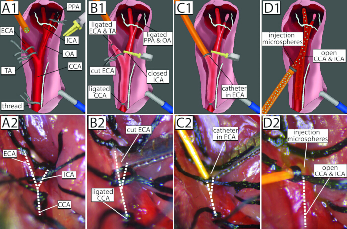
Figure 2: Microvascular embolism surgery. Detailed example pictures and schematic drawings of crucial steps during the microvascular embolism surgery. (A) Preparation of the CCA (2x), ECA (2x), TA, OA, and PPA ligations (step 2.4). (B) (Temporal) Ligation of the CCA (1st) and ECA, followed by closing the OA and PPA and temporarily closing the ICA with a vessel clip, enabling an incision in the ECA without bleeding (step 2.6.2). (C) Placement of the catheter in the dissected ECA, which are tied together with the second suture (step 2.6.7). (D) Opening of the proximal suture around the CCA and removing the vessel clip from the ICA to restore blood flow, followed by injection of the microsphere-mixture into the ICA (step 2.6.10). CCA = Common Carotid Artery; ECA = External Carotid Artery; TA = Thyroid Artery; OA = Occipital Artery; PPA = Pterygopalatine Artery; ICA = Internal Carotid Artery. Please click here to view a larger version of this figure.
3. In vivo imaging
- Two-photon microscopy
- Place the animal in the microscope's two-photon imaging holder for post-operative in vivo imaging. Maintain light anesthesia with 1.2% isoflurane in a 1 L/min mixture of 30% oxygen and 70% air, and monitor breathing frequency and depth. See Supplementary Table 1 for the microscope setup details.
- Locate lodged microspheres through the cranial window using a 10x objective (10x/0.30 DRY) and mercury lamp illumination. Then, switch to two-photon imaging with a 25x water immersion objective (25x/0.95 WATER). See Supplementary Table 2 for the imaging settings.
- Record Z-stacks around the microsphere of interest.
4. Post mortem analysis
- Experimental endpoint for in situ imaging
- When the experimental endpoint is reached, euthanize the animal by cervical dislocation, confirmed with a gap space in the cervical vertebra or a thoracotomy, under > 4% isoflurane in a 1 L/min mixture of 30% oxygen and 70% medical air.
- In situ brain imaging
- Extract the brain, embed it in 3.0% carboxymethylcellulose sodium solvent (Sigma) mixed with 0.1% black ink (VWR), and freeze at −20 °C for at least 24 h.
- Image the brain using a custom-made small 3D Fluorescent Imaging Cryomicrotome System (small-3D-FICS) previously described by Juch R.N.S. et al.40. Set the system to cut the brain vertically into 16 µm sections and image at a resolution of 13.66 × 13.66 µm. See Supplementary Table 3 and Supplementary Table 4 for the imaging settings and system specifications. Analyze the images using Articulus software41.
- In situ whole mouse imaging
- Remove the animal's skin, teeth, and tail.
NOTE: Tail removal is optional but increases imaging speed. - Embed the animal in 3.0% carboxymethylcellulose sodium solvent (Sigma) mixed with 0.1% black ink (VWR), and freeze at −20 °C for at least 24 h.
- Image the animal using a custom-made large 3D Fluorescent Imaging Cryomicrotome System (large-3D-FICS) as previously described 42. Set the system to cut 25.9 µm sections at an in-plane resolution of 26.09µm. See Supplementary Table 5 and Supplementary Table 6 for the imaging settings and system specifications. Analyze the images using Articulus software41.
- Remove the animal's skin, teeth, and tail.
Results
Post mortem in situ imaging
The success of the microvascular embolism surgery was confirmed by full-body and full-brain post mortem in situ imaging 4 days post-microvascular embolism surgery (Figure 3A). The sagittal slice of a mouse shows lodging of microspheres in the brain. Figure 3B,C show an example of an extracted mouse brain, 1 day post-microvascular embolism surgery. Microspheres were predominantly lodged in the ipsilateral hemisphere, in the flow territory of the middle and anterior cerebral arteries. Microsphere counts in brain slices were significantly increased when Tween20 was added to the mixture (Figure 3E). Monitoring the weight during the recovery after the micro-embolism surgery shows that mice lost less weight and recovered faster after surgery when injected with a microsphere mixture that contained Tween20 (Figure 3F).
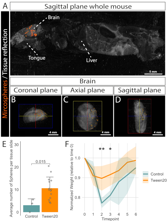
Figure 3: Distribution of microspheres in the mouse after microvascular embolism surgery. In situ localization of 10 µm microspheres in the mouse visualized using Articulus software41. (A) Sagittal plane example of a whole mouse imaged with the large-3D-FICS after microvascular embolism surgery. (B-D) Representative axial, coronal, and sagittal images of a mouse brain, imaged using the small-3D-FICS. (E) Average number of detected microspheres per 50 µm coronal brain sections at approximately bregma ± 0.5 mm for the Control and Tween20 conditions. Bars represent mean ± standard deviation. Individual measurements are shown as dots. Statistical comparison was performed using an unpaired t-test; the p-value is indicated in the graph. Outliers were identified and removed using the interquartile range (IQR) method (n = 1 for both groups), resulting in a final group size of n = 3 for controls and n = 14 for Tween20. (F) Normalized weight changes over time following microvascular embolism surgery at timepoint 0. Weights were normalized to each animal's baseline at surgery. Lines show mean ± SD per group (Control, n = 4; Tween20, n = 5) with Control in blue and Tween20 in dark orange. Statistical significance between groups at each time point was assessed using unpaired two-tailed t-tests. (* = p < 0.05, ** = p < 0.01) Please click here to view a larger version of this figure.
Microsphere injection and in vivo two-photon microscopy
During microsphere injection, catheters coated with 5% BSA showed many microspheres adhered to the catheter surface, and flowing microspheres were often clustered, which may potentially cause larger occlusions (see Supplementary Video 1). In addition, adding 5% BSA in the microsphere mixture to prevent adhesion and clustering is not desirable due to a potential immune response upon injection43,44. To circumvent this, a 0.1% Tween20 solution was used in the microsphere mixture, resulting in a visibly higher number of microspheres flowing through the catheter and in the desired number (> 20) of microspheres in the imaging window (Figure 4 and Supplementary Video 2). Figure 4A,B shows a fluorescence microscopy overview image of the brain cortex 0.5 h after the microvascular embolism surgery. Each white dot represents a microsphere that occludes a capillary in the cerebral microvasculature. Figure 4C,D displays the two-photon z-stack images 2D projection as an example. Microspheres are causing cerebral microvascular embolisms with impaired perfusion, indicated by the absence of intraluminal dye downstream of the microsphere (Figure 4E and Supplementary Video 3). Additionally, these embolisms cause disruption of the BBB with extravasation of the FITC-Dextran dye (Figure 4F,G).
These results are in accordance with the low number of microspheres adhered to the catheter and minimal microsphere clustering, which was observed in the catheter while injecting the microsphere-Tween mixture. However, a large number of microspheres did cluster together in the final 20 µL of the microsphere mixture in the catheter, which should not be injected to prevent the possible occurrence of a large infarction (see Supplementary Video 4).
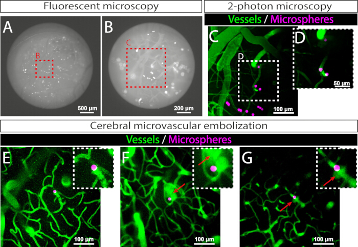
Figure 4: Two-photon in vivo microscopy of lodged microspheres. Examples of in vivo fluorescent and two-photon images of lodged microspheres in the mouse cortex. (A) Fluorescent overview through the cranial window of the lodges microspheres. (B) Fluorescent image of the selected ROI. (C,D) Two-photon microscopy images of entrapped microspheres in the cerebral microcirculation with selected ROI for detailed imaging. Z-stack images are depicted in 2D by calculating the standard deviation of pixel intensities along the Z-stack. (E-G) Representative in vivo two-photon microscopy images showing three cerebral microvascular embolisms. Red arrows highlight areas of FITC-Dextran extravasation, indicating BBB disruption and dye leakage. Please click here to view a larger version of this figure.
Supplementary Table 1: Two-photon microscope system specifications. Please click here to download this table.
Supplementary Table 2: Two-photon microscope settings for FITC-dextran and microsphere imaging. Please click here to download this table.
Supplementary Table 3: Small 3D Fluorescent imaging Cryomicrotome system settings for mouse brain imaging with blue microspheres. Please click here to download this table.
Supplementary Table 4: Small 3D Fluorescent imaging Cryomicrotome system specifications for mouse brain imaging with blue microspheres. Please click here to download this table.
Supplementary Table 5: Large 3D Fluorescent imaging Cryomicrotome system settings for whole mouse imaging with red microspheres. Please click here to download this table.
Supplementary Table 6: Large 3D Fluorescent imaging Cryomicrotome system specifications for whole mouse imaging with red microspheres. Please click here to download this table.
Supplementary Video 1: 5% BSA-coated catheter with microsphere adhesion to the catheter wall and microsphere clustering in the 25 mg/mL of FITC-Dextran microsphere mixture during injection. Please click here to download this video.
Supplementary Video 2: 0.1% Tween20-coated catheter with some microsphere adhesion to the catheter wall but without microsphere clustering in the 25 mg/mL FITC-Dextran with 0.1% Tween20 mixture with microspheres during injection. Please click here to download this video.
Supplementary Video 3: 3D segmentation of microvascular occlusions by microspheres. Please click here to download this video.
Supplementary Video 4: Final volume of the microsphere injection with high microsphere concentration in 25 mg/ml FITC-Dextran with 0.1% Tween20 mixture. Please click here to download this video.
Supplementary File 1: Microsphere adherence to pipette tips validation. Please click here to download this file.
Supplementary File 2: Immunohistochemical assessment of CD45 coverage at 1, 7, and 28 days post-microembolism surgery comparing the ipsilateral and contralateral hemispheres. Please click here to download this file.
Discussion
To model microvascular embolisms, a protocol for injecting microspheres into the cerebral circulation of mice was described that allows the study of micro-embolism using in vivo two-photon microscopy. This method optimized microsphere entrapment in the brain, with multiple microspheres trapped within the first 500 µm of the ipsilateral cortex, enabling effective two-photon imaging.
A high microsphere count in the cortical area of the brain is crucial for in vivo two-photon imaging. The loss of microspheres was minimized during the preparation of the microsphere mixture by coating the pipette tips with 5% BSA or 0.1% Tween20, reducing microsphere adhesion (see Supplementary File 1). While the exact number of adhered microspheres could not be quantified, mean intensity measurements showed the effect of the coatings. Additionally, Tween20 appeared to prevent clustering of microspheres in the catheter, resulting in a visually higher number of singular microspheres flowing through the catheter, although this is not quantified. This reduces the risk of large vessel occlusions and the potential formation of large ischemic and hypoxic regions, which is undesirable given the objective to model microvascular embolizations. Moreover, mice exhibited less weight loss and recovered to pre-surgical weights more rapidly when injected with a microsphere mixture containing low concentrations of Tween20. Tween20 is a commonly used dispersant45,46,47, therefore, the low concentrations used in this study are not expected to cause any toxicity or adverse effects on BBB integrity. In addition, our data shows that BBB leakage occurs only near (or after passing of) the microsphere lodging and not systematically, while not causing a significant increase in total leukocyte coverage (see Supplementary File 2), supporting the use of 0.1% Tween20. Overall, the addition of Tween20 contributes to reduced clumping of microspheres and an increase in microsphere delivery to the cerebral circulation, confirmed by microsphere counts in brain slices, and results in sufficient microspheres visible for two-photon microscopy. Although the use of Tween20 increases the number of microspheres lodged in the brain, variability in microsphere injection remains. Several factors may contribute to this variation. First, thrombus formation within the catheter or vasculature can cause microspheres to adhere to the clot. Second, the presence of air bubbles may interfere with smooth delivery. Finally, incomplete restoration of blood flow in the CCA or ICA can alter hemodynamics, potentially promoting microsphere adhesion to the vessel wall or clustering within the lumen. Unfortunately, these deviations cannot be detected during the injection procedure.
Polystyrene microspheres are denser than water, leading to uneven distribution once the microsphere mixture is loaded into the catheter. Most microspheres settle near the catheter wall, where fluid friction slows their movement relative to the faster central flow. This eventually results in an accumulation of microspheres within the final 20 µL of the catheter. Injecting this concentrated portion should be avoided, as it may cause large emboli and ischemic events. To prevent this, the microsphere mixture volume should be prepared at twice the intended injection volume.
The microvascular embolism surgery demands substantial training and precision. One of the most technically challenging steps involves placing a suture around the PPA, the OA, and side branches of the ICA to ensure accurate delivery of the microsphere mixture into the circle of Willis and the MCA territory. This step is complicated by the close proximity of the vagus nerve near the CCA, the small diameter of the vessels and limited surgical space, making it difficult to position the sutures without causing nerve damage or vascular injury.
While a vessel clip may be considered as an alternative to temporarily ligating the PPA using a suture, it introduces additional risks. Clips can unintentionally detach, leading to vessel reopening. Moreover, using a second clip at the PPA alongside the existing clip on the ICA, increases the likelihood of detachment of the ICA clip due to limited space. If this occurs, it will cause a significant hemorrhage and, without immediate intervention, can result in early termination of the experiment. Therefore, closure of the PPA using a vessel clip is not recommended.
The current protocol employs a catheter, rather than a syringe33, for microsphere injection. This approach offers better control over injection speed and volume, and it enables injection of the microspheres more remotely (e.g., while inside an imaging modality such as a microscope or MRI scanner).
Choosing the ECA over the CCA as the entrance point enables the CCA to stay fully open during the injection procedure, which helps maintain a more physiological cerebral perfusion throughout the surgical procedure. In addition, injecting the microspheres via the ECA instead of the CCA has other advantages48: i) reduced total operation time during reperfusion; ii) decreased risk of bleeding during injection and after surgery completion; iii) with the CCA-entrance method, an unstable stenosis and thrombosis is formed in the CCA after removing the needle49. This will cause disturbed blood flow, as well as the risk of microthrombi formation, which can end up in the brain. Additionally, entering via the CCA would involve a large risk of permanently closing the CCA, which can result in sub-optimal cerebral reperfusion during the survival period after surgery, worsened by the high variation in the circle of Willis in mice50,51
Although fully optimized, the protocol has some limitations. First, the observation that microspheres travel more slowly along the catheter walls and are not evenly distributed during injection suggests that fewer microspheres are delivered into the ICA than expected. Despite the use of Tween-20 to reduce adherence, some microspheres will still stick to the pipette tips, Eppendorf tube, and catheter. Consequently, the actual number of microspheres injected is likely lower than the calculated 7.2 x 10⁴ particles per mouse. Nonetheless, sufficient microspheres reach the cerebral circulation to allow for imaging via two-photon microscopy. The injection protocol and mixture composition are optimized for 10 µm polystyrene microspheres. If the materials used (tips, tubes, catheters) or the size of the microspheres are altered, both the solution and injection procedure should be re-evaluated accordingly. Second, studies investigating the best method for large vessel occlusion via intra-luminal occlusion of the MCA have shown that entrance of the vascular system via permanent ligation of the ECA results in ischemia of the masticatory and swallowing muscles52. This can result in decreased food intake of mice and, therefore, excessive weight loss, impaired motor function, and increased neurological deficit. However, this statement has been contradicted by others48. In this study, the weight monitoring showed an expected drop after surgery but a fast recovery to pre-surgical weights within several days, indicating that the mice do recover and eat and drink normally after permanent ECA ligation. Although the weight of the animals was monitored, this is only an indirect proxy of the animals wellbeing and does not fully rule out functional impairments like local masticatory or motor deficits. No direct assessments on functional recovery were performed, which is a limitation of this study. Another study compared the entrance of the vasculature system via the CCA or ECA and showed that entry via the CCA can result in impaired reperfusion of the cerebral circulation, concluding that the ECA entry method is preferred53. Third, proper and secure catheter placement without introducing air bubbles, blood clots, or leakage, and without obstructing flow in the CCA and ICA requires significant practice. Last, in contrast to other micro-occlusion methods like photothrombosis using Rose-Bengal injection22, one cannot predict where the microspheres will eventually lodge in the circulation.
The present study deliberately does not include negative (sham) or positive (photothrombosis) control groups, as these would not provide additional value for the primary objective. The success of this model is defined by the number of microspheres lodged within the cerebral microcirculation, particularly in the cranial window area, to enable high-resolution in vivo microscopy. A sham procedure would, by definition, yield no microspheres in the target area and thus offer no relevant comparison for the in vivo imaging endpoint. Similarly, inclusion of a photothrombosis model would address a fundamentally different pathophysiological mechanism and is therefore beyond the scope of this work, which focuses on characterizing the microvascular embolism model rather than comparing methodologies. Broader histological analyses of embolisms and their potential effect on the BBB or local neuronal tissue were not pursued, as the study was designed to prioritize in vivo 3D visualization over tissue-level validation.
The detailed surgical protocol for both the cranial window preparation and microvascular embolism model supports reliable and reproducible investigation of microvascular changes associated with microvascular embolism and the occurrence of silent brain infarcts throughout the ipsilateral hemisphere. The optimized preparation and injection of the microsphere mixture further enhance the consistency and validity of this experimental approach.
Disclosures
The authors declare no conflicts of interest.
Acknowledgements
The authors would like to express their sincere gratitude to Dr. Iwan Dobbe for developing the Articulus software, which was used for the in situ 3D image reconstructions. We also thank Prof. Dr. Nikolaus Plesnila for kindly providing TIE2-GFP mice (Jackson Laboratory, Stock No. 003658) used for in-house breeding.
This study was funded by Amsterdam Neuroscience (813294 to I.M.), Amsterdam Cardiovascular Sciences (Equipment call 2021 and 2023 to I.M.) and the Dutch Heart Foundation (03-006-2021-T019 to I.M.).
This research is also funded by the Dutch Heart Foundation and The Brain Foundation Netherlands and is conducted in collaboration with and supported by the Dutch CardioVascular Alliance, 01-002-2022-0126 CONTRAST 2.0. In addition, this work was funded in part through unrestricted funding by Stryker, Medtronic and Penumbra. The funding sources were not involved in study design, monitoring, data collection, statistical analyses, interpretation of results, or manuscript writing.
Materials
| Name | Company | Catalog Number | Comments |
|---|---|---|---|
| 27-gauge needle (0.1x16 mm) | Terumo | - | 27-gauge needle (Step 2.1.2.) |
| Articulus software | - | - | 3D analysis software (Step 4.2.2 & 4.3.3) |
| Betadine 30 ml (100 mg/ml) | Mylan | 8712207037612 | Betadine/iodine (Step 1.1.8. & 2.2.10.) |
| C&B monomer | Sun Medical | 7111 | Component of super glue (Step 1.3.1.) |
| Carbon Steel Surgical Blades (nr.15) | Swann-Morton | 205 | Blade for scratching the skull (Step 1.2.4.) |
| Carprofen (50 mg/ml) | Zoetis | - | Pain relief medication(steps 1.1, 1.6, 2.2 & 2.8) |
| Catalyzer | Sun Medical | 7110 | Component of super glue (Step 1.3.1.) |
| Catheter (ID 0,31 OD 0,64 mm) | Freudenberg | 228-0661 | Transparent catheter (Step 2.1.1.) |
| Costom made tissue hook | - | - | Tissue hook (Step 2.3.4.) |
| Cotton tips | - | - | Cotton tip (Step 1.1.8, 1.2.4 & 1.5.1.) |
| Cover glass | Warner instruments | 64-0724 | Cranial window cover glass (Step 1.4.2.) |
| Custom-made mouse headbar | - | - | Headbar for in imaging holder (Step 1.3.2.) |
| Custom-made mouse imaging holder | - | - | Imaging mouse holder (Step 1.4.1. & 3.1.1.) |
| Custom-made stereotactic frame | - | - | Stereotactic frame (Step 1.1.7.) |
| Dental cament Fluid | Kulzer | 64707937 | Component of dental cement (Step 1.3.3.) |
| Dental cemement powder | Kulzer | 64707945 | Component of dental cement (Step 1.3.3.) |
| Dental drill | Saeshin | L-206 | Drill (Step 1.4.3.) |
| Dexamethasone (4 mg/ml) | Centrafarm | - | Medication preoperative (Step1.1.4.) |
| Dissecting forceps | Braun-Aesculap | BD023R | Forceps (Step 1.2.2. & 2.3.2.) |
| drill burr bit PK/100,5 (0.5mm) | Fine Sciences | 19007-05 | Drill bit (Step 1.4.3.) |
| Duratears (3,5 g) | Alcon | - | Eye ointment (Step 1.1.8. & 2.2.7.) |
| Epoxy glue (1g) | Pattex | 9H PSMG3X | Epoxy glue (Step 1.5.2. & 2.1.1.) |
| Fine micro forceps Straight | Fine science tools | Dumont #5 | Fine micro forceps (Step 2.6.6.) |
| FITC-Dextran (70 KDa) | Sigma-Aldrich | FD70S | FITC-Dextran solution (Step 2.5.2.) |
| Isoflurane (1000 mg/g) | Laboratorios Karizoo S.A. | 118938 | Anesthesia (Step 1.1.6. & 2.2.5.) |
| large 3D Fluorescent Imaging Cryomicrotome | Custom made | - | large-3D-FICS (Step 4.3.3) |
| Lidocaine (100 mg/ml) | Aspen | - | Local anesthetic (Step 1.2.3. & 2.2.10) |
| Micro scissors Vannas 3-3/8 Inch | Braun-Aesculap | OC498R | Micro scissors (Step 2.6.2) |
| Micro Suture Tying Forceps with Round Handle | Braun-Aesculap | FD280R | Microforeceps (Step 2.3.3.) |
| Micro Suture Tying Forceps with Round Handle bent | Braun-Aesculap | FD281R | Microforeceps bent (Step 1.5.1. & 2.3.3.) |
| Micro vascular clip | Braun-Aesculap | FD562R | Vessel clip (Step 2.6.1.) |
| Micro-catheter (ID 0.23114 mm OD 0.27432 mm) | Microlumen | Micro-catheter (Step 2.1.1.) | |
| Mouse Heating Pad and Rectal Probe | Stoelting | 53800R | Heating pad (Step 1.1.2. & 2.2.2.) |
| NG2-DsRed mice | Jackson Laboratory, Bar Harbor, USA, Stock No. 008241 | ||
| Polyethylene glycol sorbitan monolaurate | Sigma-Aldrich | 9005-64-5 | Tween20 (Step 2.5.2.) |
| Polystyrene FluorSpheres Blue (365/415) | Invitrogen | F8829 | Blue microspheres (Step 2.5.1.) |
| Polystyrene FluorSpheres red (580/605) | Invitrogen | F8834 | Red microsphere (Step 2.5.1.) |
| Recovery cage | - | - | Recovery cage (Steps 1.6.2. & 2.8.2.) |
| Reverse cutting 3/8 curved needle (12mm) with suture | Bbraun | 0762067 | Suture (Step 2.7.5) |
| Ropivacaïne (2 mg/ml ) | - | - | Medication (Step 1.1.5.) |
| small 3D Fluorescent Imaging Cryomicrotome | Custom made | Small-3D-FICS (Step 4.2.2) | |
| Spongostan | Ethicon | MS0005 | Spongostan (Step 1.4.6.) |
| Surgical microscope | Euromex Microscopen B.V. | NZ.1903-B | Microscope for surgery (Step 1.2. 2.1.1.) |
| Surgical scissors | Braun-Aesculap | BC303R | Surgical scissors (Step 1.2.2. & 2.3.2.) |
| Syringe pump (for 1 ml syringes) | Havard apparatus | 70-2208 | 1 ml syringe pump (Step 2.5.6.) |
| Thread, 100m, 4/0 1.5 | Bbraun | F1134035 | 4/0.15 threads (Step 2.4.3.) |
| TIE2-GFP mice | Jackson Laboratory, Bar Harbor, USA, Stock No. 003658 | ||
| Ultra pure duster | Thorlabs | CA6-EU | Compressed air (Step 1.2.5.) |
| Universal Polymer Clear | Sun Medical | T058E | Component of super glue (Step 1.3.1.) |
References
- Hilkens, N. A., Casolla, B., Leung, T. W., de Leeuw, F. E. Stroke. Lancet. 403 (10446), 2820-2836 (2024).
- Bernick, C., et al. Silent MRI infarcts and the risk of future stroke: the cardiovascular health study. Neurology. 57 (7), 1222-1229 (2001).
- Saini, M., et al. Silent stroke: not listened to rather than silent. Stroke. 43 (11), 3102-3104 (2012).
- Smith, E. E., Schneider, J. A., Wardlaw, J. M., Greenberg, S. M. Cerebral microinfarcts: the invisible lesions. Lancet Neurol. 11 (3), 272-282 (2012).
- Adachi, T., Kobayashi, S., Yamaguchi, S. Frequency and pathogenesis of silent subcortical brain infarction in acute first-ever ischemic stroke. Intern Med. 41 (2), 103-108 (2002).
- Bokura, H., et al. Silent brain infarction and subcortical white matter lesions increase the risk of stroke and mortality: a prospective cohort study. J Stroke Cerebrovasc Dis. 15 (2), 57-63 (2006).
- Vermeer, S. E., et al. Silent brain infarcts and the risk of dementia and cognitive decline. N Engl J Med. 348 (13), 1215-1222 (2003).
- Gupta, A., et al. Silent brain infarction and risk of future stroke: a systematic review and meta-analysis. Stroke. 47 (3), 719-725 (2016).
- Georgakopoulou, T., van der Wijk, A. E., Bakker, E., van Bavel, E. Quantitative 3D analysis of tissue damage in a rat model of microembolization. J Biomech. 128, 110723(2021).
- Martinez Bravo, G., et al. Platelets in thrombosis and atherosclerosis: a double-edged sword. Am J Pathol. 194 (9), 1608-1621 (2024).
- Kell, D. B., Lip, G. Y. H., Pretorius, E. Fibrinaloid microclots and atrial fibrillation. Biomedicines. 12 (4), 494(2024).
- Hubbard, W. B., Dong, J. F., Cruz, M. A., Rumbaut, R. E. Links between thrombosis and inflammation in traumatic brain injury. Thromb Res. 198, 62-71 (2021).
- Dupré, N., Drieu, A., Joutel, A. Pathophysiology of cerebral small vessel disease: a journey through recent discoveries. J Clin Invest. 134 (10), e176987(2024).
- Idicula, T. T., Naess, H., Thomassen, L. Microemboli-monitoring during the acute phase of ischemic stroke: is it worth the time. BMC Neurol. 10, 79(2010).
- Bai, C. L., et al. A review on micro- and nanoplastics in humans: implication for their translocation of barriers and potential health effects. Chemosphere. 361, 142424(2024).
- Guan, Q., et al. The landscape of micron-scale particles including microplastics in human enclosed body fluids. J Hazard Mater. 442, 130138(2023).
- Alves, H. C., et al. Thrombus migration paradox in patients with acute ischemic stroke. Stroke. 50 (11), 3156-3163 (2019).
- Ragusa, A., et al. Plasticenta: first evidence of microplastics in human placenta. Environ Int. 146, 106274(2021).
- Rotchell, J. M., et al. Microplastics in human urine: characterisation using µFTIR and sampling challenges using healthy donors and endometriosis participants. Ecotoxicol Environ Saf. 274, 116208(2024).
- Marfella, R., et al. Microplastics and nanoplastics in atheromas and cardiovascular events. N Engl J Med. 390 (10), 900-910 (2024).
- Knezic, A., Broughton, B. R. S., Widdop, R. E., McCarthy, C. A. Optimising the photothrombotic model of stroke in the C57Bl/6 and FVB/N strains of mouse. Sci Rep. 12 (1), 7598(2022).
- Talley Watts, L., Zheng, W., Garling, R. J., Frohlich, V. C., Lechleiter, J. D. Rose bengal photothrombosis by confocal optical imaging in vivo: a model of single vessel stroke. J Vis Exp. (100), e52794(2015).
- Dietrich, W. D., Watson, B. D., Busto, R., Ginsberg, M. D., Bethea, J. R. Photochemically induced cerebral infarction. I. Early microvascular alterations. Acta Neuropathol. 72 (4), 315-325 (1987).
- Demura, N., Mizukawa, K., Ogawa, N., Yamashita, K., Kanazawa, I. A cerebral ischemia model produced by injection of microspheres via the external carotid artery in freely moving rats. Neurosci Res. 17 (1), 23-30 (1993).
- Takeo, S., et al. Sustained damage to energy metabolism of brain regions after microsphere embolism in rats. Stroke. 23 (1), 62-68 (1992).
- Georgakopoulou, T., van der Wijk, A. E., Bakker, E. N. T. P., van Bavel, E. Recovery of hypoxic regions in a rat model of microembolism. J Stroke Cerebrovasc Dis. 30 (6), 105739(2021).
- Georgakopoulou, T., van der Wijk, A. E., van Bavel, E., Bakker, E. Perivascular clearance of blood proteins after blood-brain barrier disruption in a rat model of microinfarcts. Microvasc Res. 148, 104515(2023).
- Mayzel-Oreg, O., et al. Microsphere-induced embolic stroke: an MRI study. Magn Reson Med. 51 (6), 1232-1238 (2004).
- Silasi, G., She, J., Boyd, J. D., Xue, S., Murphy, T. H. A mouse model of small-vessel disease that produces brain-wide-identified microocclusions and regionally selective neuronal injury. J Cereb Blood Flow Metab. 35 (5), 734-738 (2015).
- Shen, Y., et al. Histochemistry of microinfarcts in the mouse brain after injection of fluorescent microspheres into the common carotid artery. Neural Regen Res. 17 (4), 832-837 (2022).
- Inoue, K., Asaka, M., Lee, S., Ishikawa, K., Yanagihara, D. Gait disorders induced by photothrombotic cerebellar stroke in mice. Sci Rep. 13 (1), 15805(2023).
- Nowak, B., et al. Animal models of focal ischemic stroke: brain size matters. Front Stroke. 2, 15(2023).
- van der Wijk, A. E., et al. Microembolus clearance through angiophagy is an auxiliary mechanism preserving tissue perfusion in the rat brain. Acta Neuropathol Commun. 8 (1), 195(2020).
- van der Wijk, A. E., et al. Extravasation of biodegradable microspheres in the rat brain. Drug Deliv. 30 (1), 2194579(2023).
- van der Wijk, A. E., et al. Extravasation of microspheres in a rat model of silent brain infarcts. Stroke. 50 (6), 1590-1594 (2019).
- Rapp, J. H., et al. Cerebral ischemia and infarction from atheroemboli <100 µm in size. Stroke. 34 (8), 1976-1980 (2003).
- Lam, C. K., Yoo, T., Hiner, B., Liu, Z., Grutzendler, J. Embolus extravasation is an alternative mechanism for cerebral microvascular recanalization. Nature. 465 (7297), 478-482 (2010).
- Grutzendler, J., et al. Angiophagy prevents early embolus washout but recanalizes microvessels through embolus extravasation. Sci Transl Med. 6 (226), 226ra31(2014).
- Spaan, J. A. E., et al. Visualisation of intramural coronary vasculature by an imaging cryomicrotome suggests compartmentalisation of myocardial perfusion areas. Med Biol Eng Comput. 43 (4), 431-435 (2005).
- Juch, R. N. S., et al. Home-use hyaluronic acid jet injectors: unreliable and unsafe. Dermatol Surg. 50 (1), 62-68 (2024).
- Dobbe, J. G. G., Roo, M. G. A. D., Visschers, J. C., Strackee, S. D., Streekstra, G. J. Evaluation of a quantitative method for carpal motion analysis using clinical 3-D and 4-D CT protocols. IEEE Trans Med Imaging. 38 (4), 1048-1057 (2019).
- Demkes, E., et al. Human cardiac microtissues display improved engraftment and survival in a porcine model of myocardial infarction. J Cardiovasc Transl Res. 18 (3), 512-528 (2025).
- Lei, H. Y., Lee, S. H., Leir, S. H. Antigen-induced anaphylactic death in mice. Int Arch Allergy Immunol. 109 (4), 407-412 (1996).
- Wiedmeier, S. E., Chung, H. T., Cho, B. H., Kim, U. H., Daynes, R. A. Murine responses to immunization with pertussis toxin and bovine serum albumin: I. Mortality observed after bovine albumin challenge is due to an anaphylactic reaction. Pediatr Res. 22 (3), 262-267 (1987).
- Weiszhár, Z., et al. Complement activation by polyethoxylated pharmaceutical surfactants: Cremophor-EL, Tween-80 and Tween-20. Eur J Pharm Sci. 45 (4), 492-498 (2012).
- Castro, C. A., Hogan, J. B., Benson, K. A., Shehata, C. W., Landauer, M. R. Behavioral effects of vehicles: DMSO, ethanol, Tween-20, Tween-80, and Emulphor-620. Pharmacol Biochem Behav. 50 (4), 521-526 (1995).
- Kelava, T., Ćavar, I., Čulo, F. Influence of small doses of various drug vehicles on acetaminophen-induced liver injury. Can J Physiol Pharmacol. 88 (10), 960-967 (2010).
- Hu, Y., et al. CCA repair or ECA ligation-which middle cerebral artery occlusion is better in the reperfusion mouse model. iBrain. 9 (3), 258-269 (2023).
- Dittmar, M. S., et al. The role of ECA transection in the development of masticatory lesions in the MCAO filament model. Exp Neurol. 195 (2), 372-378 (2005).
- Zhao, L., Mulligan, M. K., Nowak, T. S. Substrain- and sex-dependent differences in stroke vulnerability in C57BL/6 mice. J Cereb Blood Flow Metab. 39 (3), 426-438 (2019).
- Bonnin, P., Mazighi, M., Charriaut-Marlangue, C., Kubis, N. Early collateral recruitment after stroke in infants and adults. Stroke. 50 (9), 2604-2611 (2019).
- Dittmar, M., Spruss, T., Schuierer, G., Horn, M. External carotid artery territory ischemia impairs outcome in the endovascular filament model of middle cerebral artery occlusion in rats. Stroke. 34 (9), 2252-2257 (2003).
- Smith, H. K., Russell, J. M., Granger, D. N., Gavins, F. N. Critical differences between two classical surgical approaches for middle cerebral artery occlusion-induced stroke in mice. J Neurosci Methods. 249, 99-105 (2015).
Reprints and Permissions
