Here, we present a detailed protocol for region-specific lens insertion and stabilization to enable reliable In vivo calcium imaging in mice, to improve reproducibility and reduce trial-and-error in calcium imaging.
A subscription to JoVE is required to view this content. Sign in or start your free trial.
Method Article
Region-Specific Lens Insertion Strategies For In vivo Calcium Imaging In Mice Across Cortical And Hippocampal Circuits
* These authors contributed equally
In This Article
Summary
Abstract
In vivo calcium imaging of neuronal populations using surgically implanted optical lenses is widely used to monitor neuronal population activity during behavior. However, surgical success and imaging quality depend critically on anatomical constraints that vary across brain regions. This protocol provides region-specific surgical guidance for the selection and implantation of imaging lenses in commonly targeted cortical and hippocampal areas. Specifically, it describes a surgical workflow encompassing target localization and skull leveling, region-specific craniotomy, and, when required, dura removal or aspiration of overlying tissue, as well as the selection, insertion, and fixation of appropriate lenses and holders. In particular, we describe three implantation strategies: conventional lens implantation for the ventral hippocampus, lens implantation with tissue aspiration for the dorsal hippocampus, and prism lens implantation for cortical imaging. We further provide practical guidance on how differences in tissue depth, vascular architecture, and circuit organization inform key surgical parameters, including lens diameter, craniotomy size, the extent of tissue removal, insertion speed, hemostatic procedures, and fixation methods. By explicitly documenting surgical considerations that are often underreported in written methods, this protocol aims to reduce trial-and-error during lens implantation, and improve experimental reproducibility. Overall, this protocol provides a practical guide for selecting and reliably implementing region-appropriate lens implantation strategies across cortical and hippocampal circuits.
Introduction
In vivo calcium imaging using implanted optical lenses has become a central technique for monitoring population-level neuronal activity in behaving animals1,2,3,4,5,6. By enabling longitudinal recordings from genetically defined neuronal ensembles, this approach has provided critical insights into the circuit dynamics underlying perception, learning, and decision making2,6,7,8. However, the success of lens-based imaging depends not only on optical access but also on careful consideration of region-specific anatomical constraints. Cortical regions such as the prefrontal cortex (PFC), mid-depth structures such as the dorsal hippocampus, and deep targets such as the ventral hippocampus differ substantially in circuit orientation and tolerance to tissue displacement, among other factors. These anatomical differences necessitate region-specific surgical strategies for lens selection and implantation. Previous studies have established reliable methods for imaging dorsal CA1 neurons in head-fixed mice using vertically implanted lenses6,9,10,11, and prism-based lenses are widely used for cortical imaging7,8, where lateral optical access enables whole- or laminar-specific recordings depending on the target circuit orientation. While these approaches share the common principle of optical access via implanted lenses, they impose distinct surgical constraints that must be addressed in a region-specific manner.
Despite the growing adoption of this technique, a common source of experimental failure lies not in conceptual misunderstanding, but in the lack of sufficiently detailed, region-specific surgical guidance. In practice, failed recordings frequently result from imprecise craniotomy, suboptimal tissue removal, or insufficient consideration of region-specific vascular and structural constraints. While general lens implantation procedures have been described in previous protocols9,10,11,12, the practical surgical nuances that determine imaging success, particularly those that differ across target regions, remain incompletely documented.
This video protocol addresses this gap by providing explicit, region-specific guidance for lens selection and implantation across cortical and hippocampal targets, using the PFC and the dorsal and ventral CA1 regions of the hippocampus as representative examples. Specifically, we describe three implantation strategies, each tailored to the anatomical and surgical constraints of the target region and highlight key decision points and technical pitfalls associated with each approach.
In dorsal hippocampal CA1 imaging, the relatively large diameter of conventional lenses often necessitates tissue aspiration to create sufficient space for implantation. If tissue removal is incomplete or improperly performed, the surrounding tissue may be compressed rather than displaced, leading to an accumulation of neurons near the lens surface and the formation of densely packed cell layers that obscure the intended imaging plane. For the ventral hippocampus, which is located deep within the brain, accurate targeting requires precise control of the insertion angle, trajectory, and penetration speed to minimize tissue damage and ensure correct positioning. By contrast, prism lens implantation for PFC imaging places greater emphasis on minimizing bleeding and preserving cortical integrity through a precise craniotomy and careful lens insertion to avoid vascular damage.
This protocol is intended for researchers planning to implement GRIN lens-based calcium imaging in cortical or hippocampal targets in rodents, particularly those who have encountered challenges in surgical reproducibility or imaging quality. It is most applicable when targeting the dorsal CA1, ventral CA1, or prefrontal cortex, and when using standard GRIN or prism lenses in combination with a miniscope or equivalent head-mounted imaging system. Researchers targeting other brain regions or using different hardware configurations should treat the region-specific principles described here as adaptable guidelines rather than fixed procedures. By explicitly documenting these practical considerations, this video aims to reduce trial-and-error, improve reproducibility across laboratories, and provide a principled framework for selecting appropriate implantation strategies.
Access restricted. Please log in or start a trial to view this content.
Protocol
All animal care and experimental procedures were approved by the Animal Care and Use Committee of the Korea Advanced Institute of Science and Technology (KAIST) under the approval number KA2025-060-V3. All experiments complied with the National Institutes of Health Guide for the Care and Use of Laboratory Animals. All efforts were made to minimize animal suffering and to reduce the number of animals used.
1. Preparatory steps for surgery
NOTE: This protocol was developed using 8-week-old adult C57BL/6J and VIP-Cre knock-in mice (RRID: IMSR_JAX:000664, IMSR_JAX:031628). The same general approach can be applied to other strains; however, some adjustments to specific details, such as target coordinates, may be required.
- Anesthetize the mouse with 3 % isoflurane delivered by inhalation at a flow rate of 1 L·min-1 in an induction chamber.
- Secure the mouse in a stereotaxic frame using ear bars and place the anesthesia mask over the snout.
NOTE: Maintain the same anesthetic concentration throughout the procedure. - Set the homeothermic system to 33.5 °C to maintain body temperature during surgery.
- Shave the surgical area and remove the residual hair with a cotton swab soaked in a chlorhexidine gluconate solution.
- Apply eye lubricant to the mouse’s eyes and cover them with small pieces of aluminum foil to protect them during surgery.
- Prior to incision, perform a toe pinch to confirm that the mouse is fully anesthetized.
- Inject the 1 % lidocaine solution (mixed with 0.5 % bupivacaine) locally at the incision site and administer the 1 % ketoprofen solution via intramuscular injection.
- Incise skin in an elliptical shape, sized to provide sufficient space for subsequent headstage implantation. Take care to avoid cutting the muscles around the skull.
NOTE: Excessive incision can induce extensive inflammation, which may interfere with long-term recordings from the same region. - Using sterile cotton swabs, gently retract the incision laterally. Clean the exposed skull surface with sterile cotton swabs and then lightly scrape with a scraper.
NOTE: This step removes debris and slightly roughens the surface to facilitate subsequent fixation of the lens and head plate. - For alignment along the anteroposterior (AP) axis, use bregma and lambda as reference landmarks. Measure the height differences between the reference points using a 26-gauge needle.
- If the AP axis is not level, loosen the anesthesia mask and adjust the height of the jaw adaptor on the stereotaxic frame until the height difference between bregma and lambda is within 0.02 mm.
- For alignment along the mediolateral (ML) axis, use points ± 3 mm from the midline as reference landmarks.
- If the ML axis is not level, reposition the ear bars properly until the left-right height difference is within 0.02 mm.
2. Craniotomy
- Mark the target locations (e.g., PFC, hippocampus) on the skull using an ink-dipped needle. When marking the target location, also mark the boundaries for drilling in the anterior, posterior, medial, and lateral directions.
NOTE: For the PFC, where implantation is guided by vascular landmarks, a 1 mm lens requires a 1.5 mm opening (Figure 1A). For the ventral hippocampus, a deep target, a 0.6 mm lens requires a 0.8 mm opening (Figure 1B). For the dorsal hippocampus, where tissue aspiration is required, a 1 mm lens requires a 1.2 mm opening (Figure 1C) to minimize the unsupported space around the lens and reduce lateral displacement during positioning before adhesive fixation. - Create a rounded-square opening using a hand drill guided by markings.
- During the initial step, drilling should be performed as vertically as possible to avoid the forming angled edges.
- Perform the drilling in multiple short steps to minimize the risk of brain damage.
NOTE: Avoid tearing the dura during this process. - When the remaining skull becomes very thin (as confirmed by gently applying pressure with forceps), lift off the bone flap using forceps, taking care not to damage the brain surface.
- Smoothen the edges at a reduced drill speed (Figure 2A). If sharp bone fragments remain along the skull edge (Figure2B), they may damage the lens or the brain surface.
- Carefully remove all bone debris generated during the drilling process. Irrigate the site with saline to remove any remaining bone fragments.
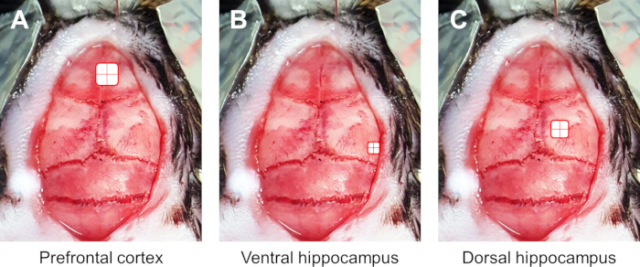
Figure 1. Representative examples of skull drilling for each target region Representative photographs of mouse skulls following craniotomy. (A) Craniotomy targeting the prefrontal cortex. (B) Craniotomy targeting the ventral hippocampus. (C) Craniotomy targeting the dorsal hippocampus. Please click here to view a larger version of this figure.
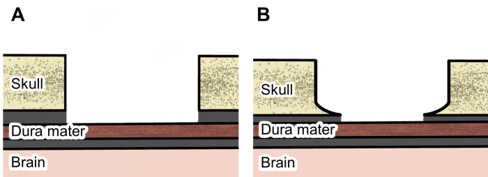
Figure 2. Skull drilling and edge finishing Schematic illustration of skull drilling and edge finishing. (A) Cross-sectional schematic of a properly finished craniotomy with a smoothly polished lower boundary. (B) Example showing sharp bone remnants caused by insufficient polishing of the lower edge. Please click here to view a larger version of this figure.
3. Pre-implantation tissue preparation
Before inserting the lens, prepare the tissue to allow stable lens insertion. Depending on the target, use either method 3.1 or 3.2.
- Dura mater removal (for ventral hippocampus, prefrontal cortex): If brain tissue aspiration is performed, removal of the dura is not necessary. However, if the lens is implanted without tissue aspiration, the dura must be removed.
- To remove the dura, slightly bend the tip of an insulin syringe needle and use it as a cutting tool.
- Carefully incise the dura in small increments. If needed, hold the incised tissue with fine forceps while cutting the remaining portions. Take care to avoid damaging the brain during this process.
- Aspiration of upper tissue (for dorsal hippocampus): Using this approach requires a minimum two-week interval between virus injection and lens implantation to prevent loss or reduction of viral expression due to aspiration.
NOTE: Performing tissue aspiration prior to viral injection is not recommended, as injection into recently damaged tissue may compromise stable expression. Conversely, allowing a prolonged recovery period after aspiration is also suboptimal, as tissue regrowth can hinder subsequent lens implantation.- Connect the pump to an 8-mm-diameter hose, which is then connected to the end of a 1 ml syringe. All connections are tightly sealed using tape to prevent air leakage.
NOTE: Use an aspiration pump capable of generating a maximum negative pressure of at least 50 kPa. Because the pump may generate substantial vibration, position it away from the surgical table. - Connect the smoothed 24-gauge needle to the end of the connected 1 mL syringe (Figure 3).
- Increase the aspiration pump pressure to at least 50 kPa.
- Carefully bring the needle tip close to the tissue so that tissue is aspirated along with saline. During this step, use one hand to manipulate the aspiration needle while using the other hand to continuously apply saline with a syringe. This prevents blood from obstructing the view and facilitates smooth aspiration.
NOTE: Although bleeding is anticipated during the aspiration process, this does not necessitate repeated aspiration–hemostasis cycles. Importantly, excessive aspiration at sites of active bleeding should be avoided, as it can exacerbate hemorrhage through additional mechanical disruption. - Perform tissue aspiration in small increments. At intervals, irrigate the surgical field with saline to assess the extent and location of tissue removal.
- Remove brain tissue above the target in a funnel-shaped volume centered on the target rather than removing tissue across the entire opening. A schematic illustration of this procedure is provided in Figure 4.
NOTE: To achieve this, do not approach the tissue from a single angle only; instead, adjust the needle to multiple angles during aspiration. - Tissue removal should stop slightly above the target region, leaving a thin layer intact. For the dorsal hippocampus, aspiration is advanced to the corpus callosum level; aspiration is stopped once the white matter beneath the cortex becomes visible (do not remove the corpus callosum).
- Connect the pump to an 8-mm-diameter hose, which is then connected to the end of a 1 ml syringe. All connections are tightly sealed using tape to prevent air leakage.
- If bleeding occurs after dura removal or tissue aspiration, apply a gelatin sponge (e.g., Cutanplast) soaked in chilled saline (4 °C) to control bleeding before coagulation. Take care to prevent blood from remaining in the surgical field.
NOTE: Instead of wiping away blood, apply gentle pressure using the sponge. - Once the brain is exposed, place the saline-soaked gelatin sponge over the area to keep the tissue moist throughout the procedure until lens implantation.
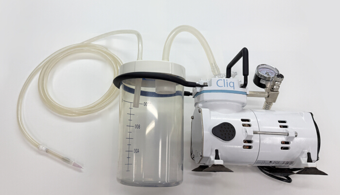
Figure 3. Aspiration device setup Photograph of the completed aspiration device assembly. The distal end of the tubing is connected to an aspiration pump, and all junctions are securely sealed to ensure stable suction. Please click here to view a larger version of this figure.
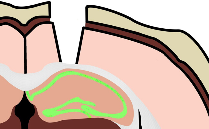
Figure 4. Tissue aspiration during craniotomy preparation A schematic illustration depicting the approximate depth and extent of tissue aspiration required for lens implantation targeting dCA1. Please click here to view a larger version of this figure.
4. Lens implantation
Two lens implantation methods will be described here. Both involve inserting the lens by advancing it into the tissue, but they differ in how the lens is applied. Select the appropriate method from Sections 4.1 and 4.2.
- Lens implantation with aluminum lens holder (for PFC and ventral CA1)
- Prior to the surgical session, ensure that the GRIN (or prism) lens is permanently fixed within the aluminum lens holder9 using super glue.
- Immediately before implantation, sterilize the protruding lens and lens holder by immersion in a 0.5 % chlorhexidine gluconate solution. Before lens insertion, ensure that the solution has completely dried.
- Mount the pre-assembled lens-holder-rod unit onto the stereotaxic frame manipulator, ensuring that the nuts are firmly tightened to prevent displacement during insertion.
- Since the lens may not be perfectly orthogonal to the holder, first manually align the threaded rod by eye to ensure that it is horizontally aligned to the stereotaxic frame or surrounding landmarks.
- Once visual alignment is achieved, use a stereo microscope to set the zero-point reference at bregma.
- Lower the lens at a constant rate of 0.5 mm·min-1 (for PFC). For deep brain areas such as the ventral hippocampus, use a slower insertion rate to minimize tissue damage and ensure accurate targeting.
- During lens implantation into the ventral hippocampus, advance the lens by 0.2 mm every 2 min until a depth of 2.0 mm is reached. Continue lowering the lens slowly from 2.0 mm to 3.0 mm.
- The advancement step is reduced to 0.1 mm every 2 minutes, beyond 3.0 mm depth.
- Lower the lens in steps of 0.05 mm every 2 minutes until the final target depth is reached.
- As this process often induces significant bleeding, apply small pieces of gelatin sponge soaked in sterile saline to the craniotomy site to maintain a clear field and control bleeding during lens advancement.
- After the lens reaches the target depth, wait at least 10 min for the surgical site to dry completely. Residual moisture can compromise adhesion of the dental cement.
- Once dry, apply the adhesive until the entire assembly is covered, leaving only the top surface of the lens holder exposed.
- After the adhesive has fully cured, to minimize mechanical shock during holder detachment, partially loosen the ear bars.
- Cut the holder's bridge with nippers. After the cut is completed, re-tighten the ear bars before proceeding with subsequent steps.
- 4.2. Lens implantation with aspiration pump (for dorsal CA1)
- Lens holder preparation: Connect the narrow end of a P1000 tip to a 4-mm-diameter rubber hose, and the opposite end of the hose is connected to a 1 mL syringe. All joints are sealed with Teflon tape to ensure airtight connections.
- Mount the hose-connected 1 mL syringe horizontally on the stereotaxic holder.
- Tip assembly: Cut the P1000 tip at 2 and 27 mm from the narrow end and keep the 2–27 mm segment. Cut the P200 tip at 24.5, 27, and 45 mm from the narrow end, and keep the 0–24.5 mm and 27–45 mm segments (Figure 5A).
- Insert the 0–24.5 mm segment of the P200 tip into the 27–45 mm segment and fix with super glue (e.g. Loctite, Figure 5B). Insert the assembled P200 segments into the P1000 tip segment and fix it with super glue. Align the central axes of all tip segments. Set the distance between the end of the P1000 tip and the narrow end of the inner P200 tip to 1 mm (Figure 5C).
- Remove the aspiration needle attached to the syringe and replace it with a lens holder attached to the stereotaxic holder (described above).
- Sterilize the lens by immersing it in 0.5 % chlorhexidine gluconate solution before loading it into the holder.
- Mount the lens holder onto the stereotaxic system and set the vacuum pump to ≥ 50 kPa. Attach the tip assembly (described above) to the holder via a press-fit and load the lens into the tip assembly using forceps.
- Lens placement: After confirming stable attachment of the lens to the tip assembly, position the lower edge of the lens at bregma as a reference point and then move to the target location. Advance the lens an additional distance equal to its radius (0.5 mm in this case) along the anteroposterior (AP) axis to align the center of the lens with the target.
- Align the tip of the lens with the medial edge of the craniotomy.
- Lower the lens 1.7 mm along the dorsoventral (DV) axis (for dorsal CA1). If bleeding occurs during advancement, slowly retract the lens, stop the bleeding, remove the blood from the lens, and restart the insertion.
NOTE: Advance the first 0.7 mm at a rate of 0.1 mm per 10 s and slowly advance the remaining 1 mm at a rate of 0.2 mm per minute. - Once the lens reaches the target, fix the lens (described below) using Superbond and dental cement after allowing the skull surface to dry completely. At this stage, take care to prevent the adhesive from contacting the interface between the lens and the holder.
- To remove the holder after fixation, turn off the vacuum, then detach the holder and hose.
NOTE: This sequence ensures that no residual negative pressure remains in the system after pump deactivation. - Lift the holder carefully to avoid dropping the tip assembly.
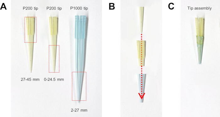
Figure 5. Tip assembly (A) Segments of P1000 and P200 pipette tips used for construction of the tip assembly. (B) Schematic of the assembled configuration. Insert the smaller P200 tip segment into the larger P200 tip segment and then fit the P1000 tip segment over the outside. (C) Fully assembled tip assembly. Please click here to view a larger version of this figure.
5. Cementing
- Apply dental resin cement (e.g. Super-Bond C&B) to cover the skull surface and the lateral surface of the lens.
- After the adhesive has fully cured, remove the lens holder as described above.
- Use the dental cement to cover the exposed skull in a dome-shaped layer. Ensure that the lens does not protrude above the level of the dental cement.
- Apply black cement or black nail polish around the lens to prevent interference from ambient light.
- To protect the lens, cover the lens surface with silicone sealant (e.g. Kwik-Cast). After the silicone sealant has hardened, apply silicone adhesive (e.g. Kwik-sil) over the dental cement (Figure 6).
NOTE: This protocol is based on the implantation of a standard GRIN lens. A secondary baseplate surgery is therefore required after recovery. Allow 4-8 weeks post-injection for sufficient viral expression, then identify the optimal focal plane before permanently fixing the baseplate.
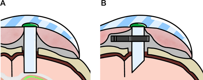
Figure 6. Cementing and sealing schematics for lens fixation Schematic illustrations of lens fixation following implantation. Superbond is applied to the lateral surface of the lens and the surrounding skull (gray). After complete curing of the superbond, dental cement is built up in a dome shape to match the height of the lens (pink). Once the cement has hardened, a silicone sealant is applied to cover the lens surface (green). Finally, silicone adhesive is applied to cover and surround the cement dome (light blue). (A) Lens fixation targeting the dorsal hippocampus. (B) Lens fixation targeting the PFC. Please click here to view a larger version of this figure.
Access restricted. Please log in or start a trial to view this content.
Results
Histological analysis following lens implantation using the above protocol confirmed accurate placement of both the GRIN lens and prism-coupled GRIN lens. In both cases, the lenses were correctly positioned to record neural activity from the medial prefrontal cortex (Figure 7A), and the CA1 region of the dorsal hippocampus (Figure 7B), respectively.
Access restricted. Please log in or start a trial to view this content.
Discussion
The success of lens-based In vivo calcium imaging depends on several surgical steps that vary across brain regions and lens geometries, each of which directly determines the quality and reliability of recorded signals. Figure 10 summarizes the overall surgical workflow for each implantation strategy. Accurate craniotomy sizing is a foundational step: an opening that is too large relative to the lens diameter reduces structural support and increases the risk of post-fixation displace...
Access restricted. Please log in or start a trial to view this content.
Disclosures
Competing interests: The authors declare that they have no competing interests.
Acknowledgements
Funding: This work was supported by the Institute for Basic Science (IBS-R002-A1).
Access restricted. Please log in or start a trial to view this content.
Materials
| Name | Company | Catalog Number | Comments |
|---|---|---|---|
| 8 mm (outer diameter) hose | Tygon | e-3603 | |
| Aspiration pump | Cliq | VC-701 | |
| Black cement (Contemporary Ortho-Jet Liquid) | Lang Dental Mfg. Co. | 1506, black | |
| Black cement (Contemporary Ortho-Jet Powder) | Lang Dental Mfg. Co. | 1530, black | |
| Bupivacaine HCl heavy injection | Myungmoon | 649801341 | |
| Chlorhexidine gluconate solution 5 % | Sungkwang | 657400190 | |
| Cutanplast (dental) | Mascia Brunelli | 5610101 | |
| Dental cement | Vertex | Type 2, Class 2 | |
| Drill bit (tip diameter: 0.5 mm) | Fine Science Tools | 19007-05 | |
| Eye lubricant (Optixcare Pet Eye Lube Plus) | Aventix Animal Health | OPX-4242 | |
| Forceps | Fine Science Tools | 11254-20, 11051-10 | |
| GRIN lens (0.6 × 7.3 mm) | Inscopix | 1050-004597 | |
| GRIN lens (1.0 × 4.0 mm) | Inscopix | 1050-004595 | |
| Homeothermic system for controlling body temperature in small animals | Harvard Apparatus | Model: HB101 | |
| Isoflurane (Terrell) | Piramal | NDC 66794-011-25 | |
| Ketoprofen Injection 100 mg/2 mL | Bukwang | 642201001 | |
| Kwik-Cast | World Precision Instruments | KWIK-CAST | |
| Kwik-Sil | World Precision Instruments | KWIK-SIL | |
| Lidocaine HCl hydrate injection 2 % | Daihan | 645104361 | |
| Nail polish (Black) | Wakemake | 11 | |
| Prism GRIN lens (1.0 x 4.3 mm) | Inscopix | 1050-004601 | |
| Saline solution | JW Pharmaceutical Corporation | 201703175 | |
| Stereo micruscope | Olympus | SZ61 | |
| Stereotaxic holder (standard electrode holder) | KOPF | Model 1770 | |
| Super bond C&B (Catalyst) | Sun Medical | 0334-0010 | |
| Super bond C&B (L-type radiopaque) | Sun Medical | 0334-0020 | |
| Super bond C&B (Monomer) | Sun Medical | 0334-0013 | |
| Surgical scissors | Fine Science Tools | 14060-10 | |
| UV glue (Norland Optical Adhesive) | Norland Products | NOA 63 |