

Overview
In this video, biomembrane force probes (BFPs) are used to measure the forces between receptors and ligands. This technique can detect interactions by monitoring the pressure needed to break the bonds between the pMHC conjugated on the probe beads and the TCRs on the target cells.
Protocol
1. Human RBCs Isolation, Biotinylation, and Osmolarity Adjustment
NOTE: Step 1.1 should be performed by a trained medical professional such as a nurse, with an Institutional Review Board-approved protocol.
- Obtain 8-10 µl (one drop) of blood from a finger prick and add it to 1 ml of the carbonate/bicarbonate buffer (Material list). Gently vortex or pipette the mixture and centrifuge for 1 min at 900 x g. Discard the supernatant and wash once more.
- In a small beaker weigh 3.5-4 mg of Biotin-PEG3500-NHS linker (Material list). Dissolve it in the carbonate/bicarbonate buffer to make the final concentration 3 mg/ml.
- Mix 171 µl of carbonate/bicarbonate buffer, 10 µl of RBC pack, and 1049 µl of Biotin-PEG3500-NHS linker solution and incubate at RT for 30 min. Wash the RBC once with carbonate/bicarbonate buffer and then twice with N2-5% buffer (Material list).
- Meanwhile, place the linker bottle with a loosened cap in a glass vacuum desiccator filled with desiccants in the bottom and vacuum for 5 min, and fill the desiccator with argon. Tighten the cap and take the bottle out. Seal the bottle with plastic paraffin film (Material list), place it into a container filled with desiccants on the bottom, and store it at -20 °C.
NOTE: The steps that involve the use of Biotin-PEG3500-NHS linker, including 1.2-1.4 (except for the incubation and wash in 1.3), need to be performed as fast as possible. - Dilute nystatin into N2-5% buffer to make a final concentration of 40 µg/ml. Mix 5 µl of biotinylated RBC with 71.4 µl of nystatin (Material list) solution and incubate for 1 hr at 0 °C. Wash twice with N2-5% buffer and store with N2-5% buffer + 0.5% BSA (Material list) in the refrigerator (4 °C).
2. Glass Bead Silanization
- Cleaning of Bead Surface
- Weigh 50 mg of glass beads powder and re-suspend them in 500 µl of DI water.
- Mix 0.5 ml of 30% H2O2 (Material list) with 9.5 ml of DI water in a 50 ml beaker, then add 2 ml of concentrated NH4OH (Material list) and bring this solution to a boiler on a hot plate.
- Add the glass beads to the boiling solution and continue to boil for another 5 min. Gently swirl the solution every min.
- After boiling, transfer ~5 ml of this hot bead suspension into a 15 ml micro-centrifuge tube and top up with RT DI water. Centrifuge at 3,500 x g for 5 min, remove and discard the supernatant.
- Transfer another 5 ml of hot bead suspension and add to the washed beads, top up with more DI water, mix well, and centrifuge again. Repeat this procedure until about 50 ml of DI water is used, which will be a total of 4 to 5 times washing.
- Transfer the bead suspension into a 1 ml vial. Repeat washing the beads with methanol (Material list) by centrifugation at 17,000 x g for 5 min 3 times, and finally re-suspend the beads in 1 ml of 100% methanol.
- Bead Surface Thiolation
- To a 50 ml centrifuge tube add 45.6 ml of methanol, 0.4 ml of acetic acid (Material list), 1.85 ml of DI water, 1.15 ml of 3- Mercaptopropyltrimethoxysilane (MPTMS) (Material list) and 1 ml beads suspension prepared in 2.1, then incubate at RT for 3 hr.
- After the reaction, remove all the reactants by washing them once with fresh methanol, and re-suspend the beads into 500 µl of methanol. Evenly divide this concentrated glass bead suspension into a set of 20 dry and clean glass vials with screw caps. Evaporate off the methanol by using a jet of dry argon and slowly rotate the vials so as to make a thin layer of dry beads on the sides of each vial.
- Place the vials of beads into a pre-heated drying oven at 120 °C for 5 min and then take out and quickly place the cap(s) loosely on. Place the vials in a glass vacuum desiccator filled with desiccants in the bottom and vacuum the desiccator with a vacuum pump until cooled.
- Purge the vacuumed desiccator with dry argon to bring the desiccator to normal atmospheric pressure. Remove the desiccator lid and quickly re-tighten the cap(s) on the vial. Seal the vials with plastic paraffin film and store them at RT in a dry dark storage box.
- Upon immediate use, take one vial of dry beads and wash once with phosphate buffer (Materials list), re-suspend into 50 µl of phosphate buffer, and store at 4 °C. This concentrated bead preparation will be referred to as "MPTMS beads" in the following steps.
Note: With proper storage, MPTMS beads could remain functional for up to three months.
3. Bead Functionalization
- Covalently Coating Proteins on Beads
- Take a certain volume (e.g., 2.5 µl) of the protein stock and mix it with an equal volume of carbonate/bicarbonate buffer to make Solution 1.
NOTE: The volume depends on the stock concentration and the desired final site density of the protein on the beads' surface. - In a small beaker weigh 2-3 mg of MAL-PEG3500-NHS linker (Material list) and dissolve it with carbonate/bicarbonate buffer to reach a final concentration of 0.231 mg/ml.
- Mix Solution 1 with an equal volume of the linker solution prepared in 3.1.2. Incubate the mixture at RT for 30 min to make Solution 2.
- Meanwhile, place the linker bottle with a loosened cap in a glass vacuum desiccator filled with desiccants in the bottom and vacuum for 5 min, and fill the desiccator with argon. Tighten the cap and take the bottle out. Seal the bottle with plastic paraffin film, place it into a container filled with desiccants on the bottom, and store at -20 °C.
NOTE: The steps that involve the use of the MAL-PEG3500-NHS linker, including 3.1.2-3.1.4 (except for the incubation in 3.1.3), need to be accomplished as fast as possible. - Mix 5 µl of MPTMS beads with Solution 2 and add phosphate buffer (Material list) to make a final volume of 250 µl.
- Incubate the beads overnight at RT, wash 3 times with phosphate buffer, and re-suspend into 100 µl of phosphate buffer, and store at 4 °C.
- Take a certain volume (e.g., 2.5 µl) of the protein stock and mix it with an equal volume of carbonate/bicarbonate buffer to make Solution 1.
- Preparing Protein/Streptavidin (SA) Coated Beads
- Follow protocol 3.1.1-3.1.4.
- Mix 5 µl of MPTMS beads with Solution 2 and 5 µl of 4 mg/ml Streptavidin-Maleimide (SA-MAL) (Material list) solution and then add phosphate buffer to make a final volume of 250 µl.
- Incubate the beads overnight at RT, wash 3 times with phosphate buffer, and finally re-suspend into 100 µl of phosphate buffer and store at 4 °C.
- Coating Streptavidin onto Glass Beads
- Mix 5 μl of MPTMS beads with 5 μl of 4 mg/ml SA solution and add 140 μl of phosphate buffer.
- Incubate the beads overnight at RT, wash 3 times with phosphate buffer, re-suspend into 50 μl of phosphate buffer, and store at 4 °C.
- Coating the SA Coated Beads with a Biotinylated Protein
- Mix 5 µl of SA-coated beads with the protein (volume depending on the desired coating density) and add phosphate buffer to make the final volume to be 100 µl.
- Incubate the mixture overnight at 4 °C or for 3 hr at RT, wash 3 times with phosphate buffer, and re-suspend into 50 µl phosphate buffer and store at 4 °C.
4. Cell Preparation
NOTE: To purify the cells, follow standard cell purification protocols corresponding to the type of cells in use, for example, T-cells or certain cell lines.
- For fBFP experiments, once the cell suspension is prepared, add Fura2-AM (Material list) dissolved in DMSO into the cell suspension to reach a final concentration of 2 µM, incubate for 30 min at RT, and then wash once. Keep this fluorescently loaded cell suspension in the dark until use.
5. Preparation for Micropipettes and a Cell Chamber
- Preparing Micropipettes
- Cut long capillary glass tubes (Material list) with a glass cutter into short pieces of around 3 inches in length. Mount one piece onto the micropipette puller (Material list), click the "Pull" button so that the middle of the capillary will be heated by the machine and the capillary will be pulled on the two ends to make two capillaries with sharp tips (raw micropipettes).
NOTE: By following the product guideline, the desired morphology of the raw pipette has a 6-8 mm taper and 0.1-0.5 µm tip. - Mount a raw pipette onto the pipette holder of the micropipette forge (Material list). Heat to melt the glass sphere on the forge. Insert the tip of the raw pipette inside the glass sphere. Cool down the glass sphere and pull the raw pipette to break it from the outside and leave its tip inside the sphere. Repeat this procedure until the desired tip orifice is obtained.
NOTE: Examples of a micropipette tip inner diameter: 2.0-2.4 µm for an RBC, ~1.5 µm for a bead, ~2-4 µm for a T-cell, and -7 µm for a hybridoma cell.
- Cut long capillary glass tubes (Material list) with a glass cutter into short pieces of around 3 inches in length. Mount one piece onto the micropipette puller (Material list), click the "Pull" button so that the middle of the capillary will be heated by the machine and the capillary will be pulled on the two ends to make two capillaries with sharp tips (raw micropipettes).
- Building a Cell Chamber
NOTE: the cell chamber is built on the basis of a homemade chamber holder, which consists of two pieces of metal squares (copper/ aluminum) and a handle that links them together (Figure 1D). - Cut a 40 mm x 22 mm x 0.2 mm coverslip using a glass cutter into two 40 mm x 11 mm x 0.2 mm pieces (coverslips 1 and 2). Glue coverslip 1 by grease to the top side of the chamber holder in the way that it bridges the two metal squares, and similarly glue coverslip 2 to the bottom side, which will form a parallel-coverslip cell chamber (Figure 1D).
- Use a pipette to inject 200 µl of experimental buffer in between the two coverslips. Make sure the buffer attaches to both coverslips. Gently rotate and shake the chamber to let the buffer touch both ends of the chamber.
- Carefully inject mineral oil into both sides of the chamber flanking the experimental buffer zone thereby sealing the buffer from the open air. Inject suspensions of probe beads (for example, pMHC-coated beads), RBCs, and targets (for example, T-cells) in the upper, middle, and lower regions of the buffer zone respectively.
4. BFP experiment
- Turn on the microscope (Material list) and light source. Place the chamber onto the main microscope stage (Figure 1A, D).
- Install all three micropipettes of BFP (Figure 1D. Left: probe, to grab an RBC, right: target, to grab a cell or bead, lower right: helper, to grab a bead).
- Use a micro-injector (Material list) to backfill a micropipette with an experimental buffer. Take off the pipette holder (Material list) and hold it at a lower place to allow water to drip from the tip. Quickly insert the micropipette into the holder tip and make sure no air bubble gets into the micropipette during the insertion. Tighten the holder screw.
- Mount each pipette holder onto its corresponding micro-manipulator. Push the micropipette towards the chamber so that their tips enter the chamber buffer area. Adjust the position of the micropipette and find them under the microscope field of view.
- Move around the chamber holder stage to find the colonies of three elements (the RBCs, the targets, and the probe beads) one by one. Adjust the position of the corresponding micropipette by turning the knobs of the manipulators to let the tip of the micropipette approach one cell/bead. Aspirate the cell/bead by adjusting the pressure inside the corresponding micropipette. All three micropipettes will capture their corresponding elements.
- Move around the chamber holder stage to find an open space away from the colonies of the injected elements where the experiment will be performed. Switch the microscope visual mode to visualize the image on the computer program on the computer screen. Move all three elements on pipette tips into the program's vision field.
- Align the probe bead and RBC, and carefully maneuver the probe bead to the apex of the RBC, briefly impinge the bead onto the RBC and gently retract. Adjust the pressure of the helper micropipette to gently blow the bead away, so that it will be left glued onto the RBC apex (Figure 1F). Move away the helper micropipette and align the target and probe bead (Figure 2A).
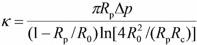
- On the program, in the vision field window use the tools in the program to measure the respective radii of the probe micropipette (Rp), the RBC (R0), the circular contact area between the RBC and probe bead (Rc ), which allows the estimation of the spring constant of the RBC (k) by the following equation, where Δp is the aspiration pressure at probe pipette tip. Note: It follows from Hooke's law that the binding force, F, can be quantified by the product of the spring constant and displacement of the probe bead (d), i.e., F = d (Figure 2C).
- Enter the desired RBC spring constant into the program (Please refer to Protocol section 4.6. The spring constant is typically set at 0.25 or 0.3 pN/nm for the force clamp assay and adhesion frequency assay and 0.1 pN/nm for the thermal fluctuation assay), which will return a required aspiration pressure in the unit of a centimeter of water. Adjust the height of the water tank that links to the probe's pipette until the required aspirating pressure is reached.
- Draw a horizontal line across the RBC apex, which will yield a curve in the adjacent window indicating the brightness (grayscale value) of each pixel along this line. Drag the threshold line to be at around half the depth of the curve (Figure 2A, B).
NOTE: The minimum point on the brightness curve below the threshold line indicates the position of the bead boundary, thus only one local minimum is allowed. If two or more local minima are at present, it indicates the image is not optimal (likely due to the image being out of focus, or a poor alignment between the probe bead and the RBC). - Select the desired experiment mode: thermal fluctuation assay, adhesion frequency assay, or force clamp assay. Set the parameters as desired (e.g., impingement force = 15 pN, loading rate = 1,000 pN/s, contact time = 1 sec, clamping force = 20 pN (for force clamp assay), etc).
- Click "Start", which allows the program to move the target pipette and drive the target in and out of contact with the probe (see Representative Results section for details). Data collection will be performed in parallel, which records the position of the probe bead in real time. Stop the program by clicking on the button "Stop experiment", at which time a window will pop out to allow saving the acquired data.

Subscription Required. Please recommend JoVE to your librarian.
Representative Results
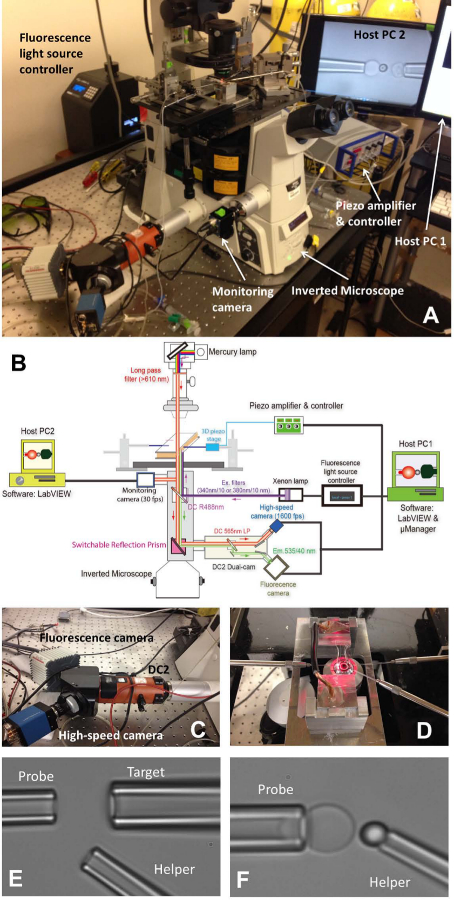
Figure 1: fBFP assembly.
(A) An overview picture of the fBFP hardware system. (B) A schematic drawing of the fBFP hardware system. (C) The dual-cam system “DC2” (orange) onto which the high-speed camera (blue) and a fluorescence camera (white) were mounted. (D) The microscope stage that adapts an experiment chamber and three micropipette manipulation systems. (E and F) Micrographs of BFP setting in an experimental chamber. (E) Micropipette assembly showing the probe pipette (left), target pipette (upper right), and helper pipette (lower right). (F) Probe bead placement. A probe bead was manipulated by a helper pipette and attached to an RBC apex to form a force probe.
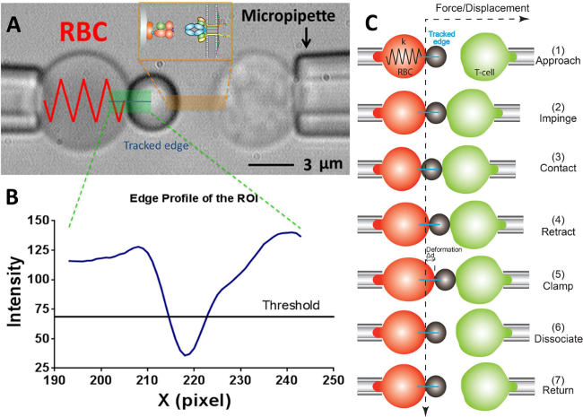
Figure 2: BFP scheme and its test cycle.
(A) Video micrograph depicting a force probe (left) and a target T-cell (right) aspirated by their respective pipettes. The stationary force probe consists of a swollen RBC and an attached ligand-bearing bead. The receptor-bearing T-cell (target) is mounted to a piezo translator aligned opposite to the probe. The ROI is indicated in green. The edge tracker is indicated in a blue line. The insert depicts the ligand (pMHC, bead side) and receptor (TCR, T-cell side) pair on the two opposing surfaces in the area marked in orange. (B) The intensity profile of the bead edge in (A). The ROI region in the x-direction is plotted as the x-axis (in pixel number) and the light intensity (in grayscale value) averaged by binning 30 pixels along the y-direction. (C) The deflection of the RBC and the position of the bead and the target (T-cell) in a test cycle of force clamp assay. The vertical and horizontal dashed lines indicate the zero-force position of the RBC apex and the time course, respectively. The line edge tracker of the RBC deformation is shown in blue on each panel. The same yet less steps are adopted in adhesion frequency assay (which lacks the steps of “clamp” and “dissociate”) and thermal fluctuation assay (which lacks the step of “dissociate”).
Subscription Required. Please recommend JoVE to your librarian.
Materials
| Name | Company | Catalog Number | Comments |
| Sodium Phosphate Monobasic Monohydrate (NaH2PO4 • H2O) | Sigma-Aldrich | S9638 | Phosphate buffer preparation |
| Anhy. Sodium Phosphate Dibasic (Na2HPO4) | Sigma-Aldrich | S7907 | Phosphate buffer preparation |
| Sodium Carbonate (Na2CO3) | Sigma-Aldrich | S2127 | Carbonate/bicarbonate buffer preparation |
| Sodium Bicarbonate (NaHCO3) | Sigma-Aldrich | S5761 | Carbonate/bicarbonate buffer preparation |
| Sodium chloride (NaCl) | Sigma-Aldrich | S7653 | N2-5% buffer preparation |
| Potassium chloride (KCl) | Sigma-Aldrich | P9541 | N2-5% buffer preparation |
| Potassium phosphate monobasic (KH2PO4) | Sigma-Aldrich | P5655 | N2-5% buffer preparation |
| Sucrose | Sigma-Aldrich | S0389 | N2-5% buffer preparation |
| MAL-PEG3500-NHS | JenKem | A5002-1 | Bead functionalization |
| Biotin-PEG3500-NHS | JenKem | A5026-1 | RBC biotinylation |
| Nystatin | Sigma-Aldrich | N6261 | RBC osmolarity adjustment |
| Ammonium Hydroxide (NH4OH) | Sigma-Aldrich | A-6899 | Glass bead silanization |
| Methanol | BDH | 67-56-1 | Glass bead silanization |
| 30% Hydrogen Peroxide (H2O2) | J. T. Barker | Jan-86 | Glass bead silanization |
| Acetic Acid (Glacial) | Sigma-Aldrich | ARK2183 | Glass bead silanization |
| 3-Mercaptopropyltrimethoxysilane (MPTMS) | Uct Specialties, llc | 4420-74-0 | Glass bead functionalization |
| Borosilicate Glass beads | Distrilab Particle Technology | 9002 | Glass bead functionalization |
| Streptavidin-Maleimide | Sigma-Aldrich | S9415 | Glass bead functionalization |
| BSA | Sigma-Aldrich | A0336 | Ligand functionalizing |
| Fura2-AM | Life Technologies | F-1201 | Intracellular calcium fluorescence dye loading |
| Dimethyl sulfoxide (DMSO) | Sigma-Aldrich | D2650 | Intracellular calcium fluorescence dye loading |
| Quantibrite PE Beads | BD Biosciences | 340495 | Density quantification |
| Capillary Tube 0.7-1.0 mm x 30 inches | Kimble Chase | 46485-1 | Micropipette making |
| Flaming/Brown Micropipette Puller | sutter instrument | P-97 | Micropipette making |
| Narishige | Narishige | Narishige | Micropipette making |
| Mineral Oil | Fisher Scientific | BP2629-1 | Chamber assembly |
| Microscope Cover Glass | Fisher Scientific | 12-544-G | Chamber assembly |
| Micro-injector | World Precision Instruments | MF34G-5 | Chamber assembly |
| 1 ml syringe | BD | 309602 | Chamber assembly |
| Micropipette holder | Narishige | HI-7 | Chamber assembly |
| Microscope (TiE inverted) | Nikon | MEA53100 | BFP system |
| Objective CFI Plan Fluor 40x (NA 0.75, WD 0.72 mm, Spg) | Nikon | MRH00401 | BFP system |
| Camera, GE680, 640 x 480, GigE, 1/3" CCD, mono | Graftek Imaging | 02-2020C | BFP system |
| Prosilica GC1290 - ICX445, 1/3", C-Mount, 1280 x 960, Mono., CCD, 12 Bit ADC | Graftek Imaging | 02-2185A | BFP system |
| Manual submicron probehead with high resolution remote control | Karl Suss | PH400 | BFP system |
| Anti-vibration table (5’ x 3’) | TMC | 77049089 | BFP system |
| 3D manual translational stage | Newport | 462-XYZ-M | |
| SolidWorks 3D CAD software | SolidWorks 3D CAD software | Version 2012 SP5 | BFP system |
| LabVIEW software | National Instruments | Version 2009 | BFP system, BFP program |
| 3D piezo translational stage | Physik Instrumente | M-105.3P | BFP system |
| Linear piezo accuator | Physik Instrumente | P-753.1CD | BFP system |
| Carbonate/bicarbonate buffer (pH 8.5) | 8.4 g/L sodium carbonate (Na2CO3), 10.6 g/L sodium bicarbonate (NaHCO3) | ||
| N2-5% buffer (pH 7.2) | 27.6 g/L NaPhosphate monobasic (NaH2PO4 • H2O), 28.4 g/L Anhy. NaPhosphate dibasic (Na2HPO4) | ||
| 20.77 g/L potassium chloride (KCl), 2.38 g/L sodium chloride (NaCl), 0.13 g/L potassium phosphate monobasic (KH2PO4), 0.71 g/L anhy. sodium phosphate dibasic (Na2HPO4), 9.70 g/L sucrose |
