

Summary
Whole-cell patch-clamp recordings from auditory nerve fiber dendrites at the inner hair cell ribbon synapse in the mammalian cochlea.
Abstract
The afferent synapse between the inner hair cell (IHC) and the auditory nerve fiber provides an electrophysiologically accessible site for recording the postsynaptic activity of a single ribbon synapse 1-4. Ribbon synapses of sensory cells release neurotransmitter continuously, the rate of which is modulated in response to graded changes in IHC membrane potential 5. Ribbon synapses have been shown to operate by multivesicular release, where multiple vesicles can be released simultaneously to evoke excitatory postsynaptic currents (EPSCs) of varying amplitudes 1, 4, 6-11. Neither the role of the presynaptic ribbon, nor the mechanism underlying multivesicular release is currently well understood.
The IHC is innervated by 10-20 auditory nerve fibers, and every fiber contacts the IHC with a unmyelinated single ending to form a single ribbon synapse. The small size of the afferent boutons contacting IHCs (approximately 1 μm in diameter) enables recordings with exceptional temporal resolution to be made. Furthermore, the technique can be adapted to record from both pre- and postsynaptic cells simultaneously, allowing the transfer function at the synapse to be studied directly 2. This method therefore provides a means by which fundamental aspects of neurotransmission can be studied, from multivesicular release to the elusive function of the ribbon in sensory cells.
Protocol
1. Solutions
- Solutions can be prepared in advance. Extracellular solutions can be stored at 4°C for up to one month. Aliquots of internal solution can be stored frozen (-20°C). Ensure that solutions are at room temperature before commencing experiments.
- Dissecting solution and extracellular recording solution (mM): 5.8 KCl; 144 NaCl; 0.9 MgCl2; 1.3 CaCl2; 0.7 NaH2PO4; 5.6 glucose; 10 HEPES; 1 Na pyruvate, pH 7.4 (NaOH), 300 mOsm. For IHC Ca2+ current isolation the extracellular solution can be modified as indicated: 5.8 KCl; 114 NaCl; 0.9 MgCl2; 1.3 CaCl2; 0.7 NaH2PO4; 5.6 glucose; 10 HEPES; 30 TEA Cl; pH 7.4 (NaOH); 300 mOsm.
- 1-2 μM tetrodotoxin (TTX) can be added to the extracellular solution to block voltage gated sodium channels and isolate excitatory postsynaptic currents or potentials (EPSCs or EPSPs).
- Intracellular recording solution (mM): 20 KCl; 110 K-methanesulfonate; 5 MgCl2; 0.1 CaCl2; 5 EGTA; 5 HEPES; 5 Na2ATP; 0.3 Na2GTP; 5 Na2phoshocreatine; pH 7.2 (KOH), 290 mOsm; or 135 KCl; 3.5 MgCl2; 0.1 CaCl2; 5 EGTA; 5 HEPES; 4 Na2ATP; 0.2 Na2GTP; pH 7.2 (KOH), 290 mOsm. Intracellular solution for IHC Ca2+ current isolation: 135 CsMeSO3; 13 TEA Cl; 3.5 MgCl2; 2.5 Na2ATP; 1 EGTA; pH 7.2 (CsOH); 290 mOsm. This solution would block a significant amount of the much larger K+ conductances, leaving Ca2+ current remaining.
2. Making Holders for Dissected Tissue
- Modified coverslips used to hold the preparation in place during recordings can also be prepared in advance.
- Apply a drop of Sylgard (Dow Corning, Midland, MI) towards the edge of a circular glass coverslip (8-12 mm). Place the thick end of a fine insect pin (FST, item no 26002-10) on the coverslip. Hold the insect pin tightly against the glass with forceps and hold near a heated coil to set the sylgard.
3. Making Electrodes
- Prepare electrodes fresh on each experimental day and store in an airtight box. Fabricate ten to twenty electrodes for each preparation.
- Select electrode glass; we use 1 mm borosilicate glass capillaries (1B100F-4 from WPI, Sarasota, FL).
- Design a program on a multi-step puller to pull electrodes with a tip diameter of approximately 2-3 μm (~ 6 MΩ in solutions described above). We use a Sutter P-87 multi-step horizontal puller or a Narishige vertical PC-10 puller.
- Carefully coat the shank of the electrode with Sylgard as close to the tip as possible. This decreases pipette capacitance and minimizes recording noise.
- Fire-polish electrodes using a microforge with a heated filament such as that available from WPI. Fire polished electrodes should have an outer tip diameter of approximately 1 μm (10-15 MΩ in solutions described above). The thickness of the pipette wall is about 1/3 μm. The outside diameter has about the size of the afferent bouton to be patched.
- In case of implementing simultaneous recordings: IHC pipette should be constructed in the same manner (same glass, same pulling program), with the distinction that fire polishing should leave a larger tip diameter of ~ 3 μm (6 - 8 MΩ).
4. Setting Up the Experiment
- Fill chambers connected to the gravity fed perfusion system with extracellular solution and test solutions containing drugs or toxins of interest.
- Set perfusion so that bath volume is approximately 2 mL, constantly perfuse at a rate on the order of 1.5 mL min-1.
- If different solutions are to be applied during the experiment with a local perfusion system, fill reservoirs with solutions. Run solutions through the system and ensure that there are no air bubbles.
5. Dissection and Sample Preparation
- The accompanying movie illustrates the dissection of the organ of Corti for three-week old rats (Sprague Dawley, Charles River), which is more difficult than that of earlier postnatal stages. Benefits and drawbacks of recording from rats of different ages are reviewed in the discussion.
- Deeply anaesthetize the rat by isoflurane inhalation. When withdrawal reflexes are absent and corneal reflexes are severely depressed, decapitate. These procedures have been approved by the Johns Hopkins University Animal Care and Use Committee.
- Remove the snout and skin from the decapitated head. Bisect the head and remove the brain to expose the temporal bones.
- Remove both temporal bones and place in clean dissecting dishes containing standard extracellular solution.
- Remove the bone encapsulating the temporal bone so as to expose the cochlea. Hold the temporal bone securely at the base with a pair of forceps. Identify the round and oval windows. Orientate the cochlea so that the oval window and spiraling side of the cochlea face upwards and remove excess bone around the cochlea.
- Remove the bone encapsulating the cochlea to expose the sensory epithelium, taking care to protect the apical coil, which will be used for the experiment. Use a second pair of fine forceps to chip the bone directly off the cochlea, beginning with the area that is more transparent than the rest of the bone. Here the bone is thinner and easier to remove. Continue removing the bone from around the apical coil.
- Use micro-dissecting scissors to cut through the modiolus beneath the apical turn. Then disconnect the apical turn from the lower turns of the cochlea.
- Use micro-dissecting scissors again, if necessary, to ensure that the apical turn is completely severed. Take care to protect the apical coil; it should not be pulled or stretched. Use the fine forceps to coax the apical turn from the rest of the cochlea.
- Remove the rest of the bone from both sides of the apical turn.
- Carefully remove the stria vascularis, the shiny strip of tissue situated outside the hair cell region (Schematic 1). Make sure to avoid removing the sensory hair cells, which can easily become detached along with the stria vascularis.
- Use fine forceps to detach the tectorial membrane, the shiny, semi-transparent membrane that sits above the sensory hair cells.
- Now trim excess tissue and bone and flatten the preparation with the forceps. This is necessary, so that the tissue can be placed evenly under a pin.
- Place the preparation under the pin attached to a coverslip (prepared previously), taking care to position the pin away from the hair cells.
- Use forceps to transfer the coverslip to the recording chamber. Ensure the cochlear tissue is completely covered with a drop of extracellular solution whilst transferring the coverslip. Press the coverslip down firmly onto the glass bottom of the chamber to ensure that it does not move during the recording.
- Immediately begin perfusion with extracellular solution, to ensure better survival of the preparation.
6. Recording
- Locate the preparation through the microscope eyepieces using the 10x and the 40x water immersion DIC objectives. Orientate the preparation so that recording electrodes can approach IHCs orthogonally to the lateral wall of the IHC.
- If the preparation is curled over, limiting visibility of the basal region of IHCs, use a recording electrode to push the outer edge of the preparation down against the glass coverslip, taking care to avoid pressing the IHCs themselves.
- * If using young rats, at this stage the thick layer of supporting cells above the hair cells can be removed with a cleaning pipette (with a tip diameter of ~ 10-20 μm) to gain access to the sensory cells 1, 12.
- Use the monitor to assess whether the tissue is healthy. Using a 4X magnification lens between microscope and the NC70 Newvicon camera further magnifies the image and projects an area of about 4800 μm2 on the monitor. Hair cells should be elongated with intact hair bundles. When the tissue deteriorates, hair cells swell and become more transparent and grainy.
- Localize afferent boutons around the base of the IHCs. Boutons are spherical or ellipsoidal, approximately 1 μm in diameter and are light in color with a shiny appearance. The majority of boutons are localized below the level of the nucleus. When the tissue is unhealthy boutons swell to approximately 4 times the normal size and become transparent, rather than shiny.
- Fill a recording electrode with intracellular solution, apply positive pressure and use the micromanipulator to manoeuvre the electrode to the preparation.
- Make an incision in the preparation at the level of the IHC base with the electrode. Push the electrode between the thin layer of supporting cells and the IHCs, using positive pressure to forge an access route to the area at the base of the IHCs. This step is "key" for reaching the afferent bouton and for not recording from supporting cells that tightly ensheath the afferent endings.
- Carefully remove the electrode and replace with a freshly filled electrode.
- Using positive pressure to maintain a clean electrode tip, manoeuvre the electrode through the access hole to the membrane of the IHC. The positive pressure should assist in moving around the supporting cells surrounding the IHCs.
- Move the electrode around adjacent supporting cells towards the afferent bouton (as shown in the accompanying movie. An alternative approach is to approach the afferent bouton by moving along the IHC membrane until the tip of the electrode touches the bouton). Ensure that the electrode tip is directly in front of the afferent bouton (there is still a small gap between the bouton and the electrode due to the positive pressure on the pipette). Boutons offer more resistance to movement of the pipette than the supporting cells and the IHC membrane; they can be "felt" by the experimenter.
- Move pipette up and down and push to make sure that the bouton moves. This indicates that the pipette tip and bouton are in the same Z-plane.
- With the electrode pressed against the afferent bouton, simultaneously release positive pressure and apply suction to form a GΩ seal. Formation of a GΩ seal on an afferent bouton is similar to that onto a hair cell. Seal formation can be rapid or may occur slowly.
- Apply gentle bursts of suction to rupture the membrane within the electrode and enter the whole cell recording configuration.
- If the cell patched is an afferent bouton, small capacitative transients will appear on the test square pulse monitored during seal formation (see Figure 1). We have estimated the capacitance of the afferent ending to be 0.4 - 1.8 pF (see 3, 4). If the cell patched is an IHC, transients will be on the order of 3-5 times larger depending on access resistance.
- To confirm that the cell is an afferent bouton, run a protocol with hyperpolarizing and depolarizing voltage steps. The current voltage relations (IVs) for afferent fibers and IHCs (often patched mistakenly when aiming for an afferent bouton) are characteristic for the individual cell types and are shown in Figure 2.
- Monitor the membrane potential; for an afferent fiber, it is normally around -60 to -65 mV.
- If the cell is not an afferent bouton, remove electrode and repeat steps 8 - 13 with a freshly filled electrode. Use a new electrode for each attempt.
- Monitor series resistance throughout the recording by applying voltage steps to ensure that the seal is not closing up. If series resistance increases, it can be helpful to apply gentle pulses of suction or to move the electrode backwards slightly. Series resistances are typically around 30 MΩ. When analyzing synaptic activity, we discard recordings with series resistances larger than 50 MΩ.
- You can now record synaptic activity (see Figure 3). Either the afferent fiber exhibits spontaneous activity, or the hair cell needs to be depolarized to activate transmitter release. Applying an extracellular solution with a higher potassium concentration (for example 40 mM) will depolarize the hair cell and often activate or increase the rate of transmitter release.
- For simultaneous recordings of IHCs and afferent boutons 2, the procedure should be modified in the following manner: Proceed through steps 1 to 5. Fill an IHC pipette with the corresponding intracellular solution for Ca2+ current isolation and follow as indicated in 6. Leave the pipette for IHC recording in "waiting position" close to the IHC to be recorded from. Continue with steps 6 - 14 for afferent recording. When the afferent pipette is in whole cell configuration continue with the IHC pipette. Manoeuvre the second pipette towards the lateral wall of the corresponding IHC, always maintaining positive pressure. The IHC should show an indentation on the lateral wall by means of the pressure and it needs to be ensured that the supporting cells are separated from it. Steps 12 - 13 could be applied for IHC as well. As indicated in 14, compared to the afferent fiber, larger capacitive transients are a hallmark of an IHC recording, in addition to the characteristic IV relation. Once simultaneous recordings are established, some time should be allowed (3 - 5 min, depending on series resistance) for intracellular solutions to wash into the IHC. This will result in larger Ca2+ currents due to increasing block of much larger K+ conductances.
- In order to perform loose-seal extracellular recordings, at step 12, rather than making a GΩ seal, make a loose seal of about 30 to 50 MΩ onto the afferent bouton. This can be achieved by applying less suction whilst releasing the positive pressure. See Figure 5 for an example of an extracellular recording from a P21 rat afferent bouton.
7. Trouble Shooting
- If seals can be formed, but the transition from cell-attached to whole cell recording cannot be achieved, the inner diameter of the pipette may be too narrow.
- If tight seals can not be formed, the inner pipette diameter may be too large and the whole bouton could be sucked up into the electrode.
- If all synaptic events are small and uniform, the recording may be extracellular to the afferent. Test for reversal of events at positive membrane potentials; intracellularly recorded EPSCs will reverse at positive potentials.
- If series resistances are consistently high when patching afferent terminals, try moving the pipette backwards before attempting to break through into the whole cell configuration. This helps to prevent pipette clogging and high access resistance.
- Correct position of pipette fearlessly. It is possible to move the electrode to reduce high series resistance or pipette clogging without "loosing" the seal on the afferent. During simultaneous recording establishment, the IHC is usually 'pushed' towards the bouton. The afferent pipette position can be corrected accordingly.
8. Representative Results
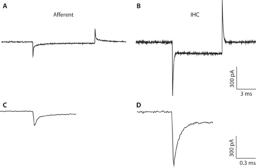
Figure 1. A-B. Typical transients recorded from an afferent fiber (A) and IHC (B) in response to a 10 mV hyperpolarizing voltage command from a holding voltage of -94 mV. Due to the narrow pipette diameter and high access resistance, the IHC recording (B) is suboptimal for whole cell IHC recording. The recording is shown here only to illustrate the difference between the capacitative transients from IHCs and afferent fibers. This can help to distinguish between the cell types when forming the whole-cell configuration. Whole-cell capacitative transients from IHCs are on the order of 5 times larger in amplitude than those from afferent fibers. C-D. Transients from A & B shown on an expanded timescale. C. The decay of the afferent response can be fit with two exponentials. The capacitance of the afferent ending was estimated from the fast component.

Figure 2. IV relations from an afferent bouton (A) and an IHC (B). IV relations are recorded from a holding potential of -84 mV with voltage steps from -124 mV to + 36 mV in 10 mV increments (nominal voltages). Voltages are shown to the right of some traces. These recordings were carried out with 5.8 mM extracellular KCl at room temperature. Scale for both: 500 pA, 200 ms.
A. IV relations from an afferent fiber at postnatal day 19. EPSCs are present during the majority of the voltage steps; EPSCs reverse positive to +6 mV. This recording was carried out in the presence of TTX to block voltage gated Na+ currents. Note the slowly activating inward current at hyperpolarizing voltages (Ih). This current is not present in IHCs or supporting cells and provides a good indication that the cell recorded from is an afferent fiber (see 3). B. IV relations from a P19 IHC. Due to the narrow pipette diameter and high access resistance, the recording is suboptimal for characterizing IHC currents and the currents are smaller than expected. The recording is shown here only to demonstrate the IV relations of IHCs and afferent fibers can be clearly distinguished, when an afferent fiber recording is attempted. Note the fast activating outward K+ currents at positive potentials (arrow) followed by delayed rectifier K+ currents 13.

Figure 3. Exemplar synaptic currents recorded from an afferent fiber at postnatal day 21 in the presence of 40 mM extracellular K+ to increase the rate of release from the IHC. Room temperature, with TTX applied to block voltage gated Na+ currents. A. Scale 200 pA, 5 ms, note the variable size and shape of EPSCs. For a detailed description of EPSC characteristics see 4. B. Two EPSCs marked in A (#: multiphasic, o: monophasic) shown on an expanded scale: Scale 100 pA, 1 ms.

Figure 4. Simultaneous recording of an IHC and contacting afferent bouton in an excised rat organ of Corti, postnatal day 10 (also see 2). A voltage step depolarizing the IHC provokes release of neurotransmitter and activates EPSCs in the afferent bouton. Upper trace: Voltage protocol for IHC depolarization. Holding potential: -79 mV, 50 ms step to -29 mV. Middle trace: L-type Ca2+ currents recorded from the IHC typically show little inactivation and activate at negative potentials. Bottom trace: Synaptic currents in the afferent fiber in response to IHC depolarization. Note the synaptic depression during a 50 ms IHC depolarization.

Figure 5. A. Exemplar extracellular recording from an afferent bouton at postnatal day 21. This was recorded at room temperature, with 5.8 mM extracellular K+. This recording has a typical signal to noise ratio for a recording in a preparation from a three week old rat. B. Average waveform for extracellular events recorded from a P20 afferent bouton. This is the average waveform from 10272 events.

Schematic 1. Cross sectional view through one turn of a rat cochlea illustrating the anatomical relation between the inner and outer hair cells, the spiral ganglia, stria vascularis and tectorial membrane.
Discussion
The critical step in this procedure is the dissection. If the tissue is stretched or damaged during the dissection, afferent fibers will not survive. Tissue from younger rats is more elastic and forgiving. We find that postnatal days 10 to 11 are easiest to dissect and experiments have higher success rates. A significant degree of cochlear maturation occurs postnatally, with rats beginning to hear from around postnatal day 12 14. Therefore, at the age where the dissection is easiest, synapses may not be fully mature 4.
The dissection described here for rats is essentially the same for mice, the main difference being the smaller size of the mouse cochlea. This technique allows the properties of ribbon synapses to be examined in transgenically modified mice 15. Further modifications to this technique include: adding a fluorescent dye to the intracellular solution to label fibers 3; paired recordings with the presynaptic inner hair cell and postsynaptic afferent bouton, allowing the transfer function between pre and post synaptic cells to be determined 2 and loose-seal extracellular recordings at afferent boutons to avoid loss of cellular integrity. The extracellular recording configuration is easier to attain than the whole-cell configuration and experiments are generally longer lasting.
Disclosures
No conflicts of interest declared.
Acknowledgments
This work was supported by a Deafness Research Foundation Research Grant to EY and NIDCD DC006476 to EG and by NIDCD DC005211 to the Center for Hearing and Balance, Johns Hopkins University. Artwork copyright Tim Phelps, Johns Hopkins University.
LG wrote the initial manuscript; EY and LG filmed the dissection and the recording. All authors provided exemplar figures and contributed to writing the manuscript.
Materials
| Name | Company | Catalog Number | Comments |
| Air table | TMC | ||
| Gibraltar Stage with xy-table | Burleigh | ||
| Axioscope FS2 upright microscope DIC optics Green filter | Carl Zeiss, Inc. | ||
| Newvicon camera with controller | Dage | ||
| Monitor | Dage | ||
| Multiclamp 700B (or similar) | Molecular Devices | ||
| Digidata 1322A (or similar) | Molecular Devices | ||
| Manipulator MP285 | Sutter Instrument Co. | ||
| 6-channel valve application system for local perfusion (used with hand made perfusion pipettes) | Warner Instruments | ||
| PC with acquisition software (PClamp) | Molecular Devices | ||
| Above is the equipment in our electrophysiological setups used for recording from afferent terminals. | |||
References
- Glowatzki, E., Fuchs, P. A. Transmitter release at the hair cell ribbon synapse. Nat Neurosci. 5 (2), 147-154 (2002).
- Goutman, J. D., Glowatzki, E. Time course and calcium dependence of transmitter release at a single ribbon synapse. Proc Natl Acad Sci U S A. 104 (41), 16341-16346 (2007).
- Yi, E., Roux, I., Glowatzki, E. Dendritic HCN channels shape excitatory postsynaptic potentials at the inner hair cell afferent synapse in the mammalian cochlea. J Neurophysiol. 103 (5), 2532-2543 (2010).
- Grant, L., Yi, E., Glowatzki, E. Two modes of release shape the postsynaptic response at the inner hair cell ribbon synapse. J Neurosci. 30 (12), 4210-4220 (2010).
- LoGiudice, L., Matthews, G. The role of ribbons at sensory synapses. Neuroscientist. 15 (4), 380-391 (2009).
- Singer, J. H. Coordinated multivesicular release at a mammalian ribbon synapse. Nat Neurosci. 7 (8), 826-833 (2004).
- Keen, E. C., Hudspeth, A. J. Transfer characteristics of the hair cell's afferent synapse. Proc Natl Acad Sci U S A. 103 (14), 5537-5542 (2006).
- Li, G. L. The unitary event underlying multiquantal EPSCs at a hair cell's ribbon synapse. J Neurosci. 29 (23), 7558-7568 (2009).
- Singer, J. H., Diamond, J. S. Vesicle depletion and synaptic depression at a mammalian ribbon synapse. J Neurophysiol. 95 (5), 3191-3198 (2006).
- Suryanarayanan, A., Slaughter, M. M. Synaptic transmission mediated by internal calcium stores in rod photoreceptors. J Neurosci. 26 (6), 1759-1766 (2006).
- Neef, A. Probing the mechanism of exocytosis at the hair cell ribbon synapse. J Neurosci. 27 (47), 12933-12944 (2007).
- Tritsch, N. X. The origin of spontaneous activity in the developing auditory system. Nature. 450 (7166), 50-55 (2007).
- Kros, C. J., Ruppersberg, J. P. Expression of a potassium current in inner hair cells during development of hearing in mice. Nature. 394 (6690), 281-284 (1998).
- Muller, M. Developmental changes of frequency representation in the rat cochlea. Hear Res. 56 (1-2), 1-7 (1991).
- Seal, R. P. Sensorineural deafness and seizures in mice lacking vesicular glutamate transporter 3. Neuron. 57 (2), 263-275 (2008).
