Magnetic tweezers, a powerful single-molecule manipulation technique, can be adapted for the direct measurements of the twist (using a configuration called freely-orbiting magnetic tweezers) and torque (using a configuration termed magnetic torque tweezers) in biological macromolecules. Guidelines for performing such measurements are given, including applications to the study of DNA and associated nucleo-protein filaments.
Method Article
Magnetic Tweezers for the Measurement of Twist and Torque
In This Article
Summary
Abstract
Single-molecule techniques make it possible to investigate the behavior of individual biological molecules in solution in real time. These techniques include so-called force spectroscopy approaches such as atomic force microscopy, optical tweezers, flow stretching, and magnetic tweezers. Amongst these approaches, magnetic tweezers have distinguished themselves by their ability to apply torque while maintaining a constant stretching force. Here, it is illustrated how such a “conventional” magnetic tweezers experimental configuration can, through a straightforward modification of its field configuration to minimize the magnitude of the transverse field, be adapted to measure the degree of twist in a biological molecule. The resulting configuration is termed the freely-orbiting magnetic tweezers. Additionally, it is shown how further modification of the field configuration can yield a transverse field with a magnitude intermediate between that of the “conventional” magnetic tweezers and the freely-orbiting magnetic tweezers, which makes it possible to directly measure the torque stored in a biological molecule. This configuration is termed the magnetic torque tweezers. The accompanying video explains in detail how the conversion of conventional magnetic tweezers into freely-orbiting magnetic tweezers and magnetic torque tweezers can be accomplished, and demonstrates the use of these techniques. These adaptations maintain all the strengths of conventional magnetic tweezers while greatly expanding the versatility of this powerful instrument.
Introduction
In recent years, single-molecule techniques have proven their wide applicability in the study of processive motor proteins and other enzymes, yielding insight into their kinetics and the underlying mechanochemistry. In the context of force spectroscopy, important contributions have been made by atomic force microscopy flow stretching, and optical and magnetic tweezers. Optical and magnetic tweezers (MT) have notably succeeded in combining great flexibility in terms of molecular manipulation with high spatial and temporal resolution. Here, we focus on MT, which can apply both stretching forces and torques to biological molecules tethered between a surface and superparamagnetic beads1-3.
Magnetic tweezers (MT, Figure 1a) are a very versatile single-molecule technique that has been used to monitor both the mechanical properties of nucleic acids as well as their interactions with proteins. MT have many strengths, including overall simplicity and robustness of the experimental implementation, facile application of torque, natural operation and straightforward calibration in constant force mode4, extension to parallel measurements5,6, and absence of sample heating and photodamage. Compared to other single-molecule approaches, MT provide a way to perform force-dependence measurements at forces as low as ≈ 10 fN and have the ability to straightforwardly control the degree of supercoiling. While MTs have predominantly been used as an experimental tool to investigate biological processes involving nucleic acids7,8, they have also found application in studies of the mechanical properties of proteins9-13 or cells10,14-17. Numerous useful references are available that describe how to build and run a MT4,18-20.
However, conventional MT do not track rotational motion directly, and, while they apply torque, they do not measure torque directly. In addition, they constrain the free rotation of the nucleic acid tether. Here, we present two extensions of magnet tweezers. The first, termed freely-orbiting magnetic tweezers (FOMT, Figure 1b)21, allows the measurements of equilibrium angle fluctuations and changes in the twist of tethered nucleic acid molecules, without constraining the rotational motion around the tether axis. The second, termed magnetic torque tweezers (MTT, Figure 1c), which has the capability to apply and directly measure both forces and torques to single biomolecules22-27.
In the following protocol, we presume that the reader has at his/her disposition a ‘conventional’ MT instrument. We refer the reader to the Discussion for references on how to build and run a MT set up, as well as considerations that must be taken into account in the selection of magnetic beads, magnets, and tracking routines. In addition, sections 1 and 2 of the Protocol Text describe how we typically prepare and incubate a DNA sample for use in the MT as well as the preliminary measurements that can be performed on a single DNA in the conventional MT. Sections 3 and 4 of the Protocol Text illustrate how an MT instrument can be readily adapted and used for FOMT and MTT measurements.
Protocol
1. Preparation and Incubation of a DNA Sample
- Prepare DNA constructs that are ligated to duplex ends (typically employ ≈ 600 bp DNA PCR fragments) that are functionalized with multiple biotin and digoxigenin groups, respectively18. To start, a DNA tether length > 1 µm, e.g., a 7.9 kbp corresponding to a stretched length of ~2.7 µm as employed here, is recommended for ease of use; in particular, using a DNA length that is similar to or shorter than the bead radius is problematic due to the attachment geometry in the MTT and FOMT. See the Discussion for a description of how DNA length influences temporal response in the angular domain.
- Assemble the flow cells for single-molecule experiments. For the flow cells, use two glass microscope coverslips separated by a double-layer Parafilm spacer. The top microscope coverslip should have two holes for the fluid in- and outlets to the cell. It is convenient to use a sandblaster to drill the holes. The bottom coverslip is coated with nitrocellulose (0.1% wt/vol in amyl acetate). Place the Parafilm spacers on the nitrocellulose-coated side of the bottom slides and close the top with clean top slides.
- Seal the flow cells. Using physical tweezers, place the assembled flow cell on a heater plate set to 80-100 °C for ~1 min. Pay attention that the flow cell is well sealed, that the Parafilm does not close off the holes that connect to the in- and outlet, and that the glass slides are well aligned.
Note: To ensure a good seal, it is recommended to stroke out bubbles in the Parafilm using a large cotton swab. The flow cell can then be mounted on the magnetic tweezers instrument. - Prepare buffers. Prepare TE tethering buffer (10 mM Tris-HCl, pH 8.0, 1 mM ethylenediaminetetraacetic acid (EDTA), and 200 mM NaCl). Alternatively, one can use PBS buffer (137 mM NaCl, 2.7 mM KCl, 10 mM phosphate buffer, pH 7.4) supplemented with 100 μg/ml BSA, 0.1% Tween and 5 mM sodium azide (PBS+) as tethering buffer. Flush 2-3 cell volumes TE tethering buffer into the flow cell.
- Incubate 0.5 or 1.5 μm radius non-magnetic latex beads in the flow cell for ~30 min. These beads will act as reference beads during magnetic tweezers measurements that allow one to minimize the effect of drift between the objective and the sample holder (i.e. the flow cell). Flush out unattached non-magnetic beads by rinsing with 2-3 cell volumes of TE tethering buffer.
- Functionalize the bottom surface of the flow cell by incubation with 100 μg/ml anti-digoxigenin in PBS for at least 1 hr (preferably longer; incubation can be carried out overnight), to provide for DNA attachment. Rinse with 2-3 cell volumes of TE tethering buffer. Finally incubate the flow cell with 2 mg/ml bovine serum albumin (BSA) in TE tethering buffer for 30 min for surface passivation.
- Take an aliquot of 2 ml streptavidin-coated superparamagnetic MyOne beads (see Discussion and Table of Materials) and dilute with 10 ml TE tethering buffer. Wash twice with 10 ml TE tethering buffer using a magnetic particle concentrator, and resuspend in 10 ml TE tethering buffer. Attach ~1 ml of the DNA molecules (approximately 1 ng) to these beads by incubation in TE tethering buffer for 30 min.
- Dilute the solution of the DNA-tethered superparamagnetic beads ten-fold by adding 90 ml TE tethering buffer. Finally, inject the solution into the flow cell and incubate for ~1 hr to allow for DNA attachment to the anti-digoxigenin-coated surface. Wash the flow cell thoroughly with TE tethering buffer. After incubation of the DNA-tether constructs, flush extensively with experimental buffer (this can be TE tethering buffer) to remove all non-attached beads.
- For measurements that employ an angular tracking protocol that requires fiducial marker beads attached to the magnetic beads23 (see Discussion), incubate the flow cell with 1,000-fold diluted stock of marker beads in TE tethering buffer for at least 30 min and rinse with the buffer thoroughly.
2. Measurements on a Single DNA Molecule in the Conventional Magnetic Tweezers
- Using a conventional MT (see Discussion) with appropriate field configuration (Figure 1a) and both translational and rotational control of the magnet position, search for rotationally constrained DNA molecules in the flow cell. At pulling forces of ≥ 1 pN (consult references 4,19,20,28,29 regarding force calibration in magnetic tweezers), tethered beads can easily be distinguished from beads stuck to the surface of the bottom slide by their different heights in the focus. Whether a DNA molecule is rotationally constrained can be assessed by introducing 20-30 turns of the magnets at a force of ≈ 0.25 pN: here, the tether length should decrease by 0.4-0.5 μm.
Note: To run magnetic tweezers experiments, image processing is used to determine the x,y, and z position of DNA-tethered beads. Custom Labview software for this purpose is available from the authors upon request.- Verify that the bead is attached by a single DNA tether. This can be done by comparing the behavior under positive and negative turns at forces of > 1 pN (Figure 2a). In this force regime, the presence of multiple DNA tethers will give rise to an approximately symmetric decrease in the extension upon introducing positive and negative turns, whereas single DNA tethers will give rise to an asymmetric response.
- Search for appropriate fixed beads stuck to the bottom surface in the vicinity of the tether of interest that can serve as reference beads.
- Calibrate the length of the DNA, l. The position of the flowcell surface can be determined by bringing the tethered bead in contact with the surface (e.g., by rotating the magnet by ~60 turns at a force below 0.2 pN). Measurements of the tethered bead’s vertical position with respect to this surface then report on absolute value of l.
Note: To minimize subsequent effects of drift, it is advised to perform measurements of l relative to the position of a reference bead affixed to the surface. - Record a rotation curve (i.e. a measurement of the DNA extension as a function of the number of turns) at a stretching force of ≈ 0.25 pN (Figure 2a).
- Determine the number of turns at which the extension is maximal, as this corresponds to the state at which the DNA molecule is torsionally relaxed. To do so, it is useful to fit the rotation curve locally with a parabolic or a Gaussian function to determine the center position. Define this point as “zero turns”.
Note: A custom-written routine for this purpose is available from the authors upon request.
- Determine the number of turns at which the extension is maximal, as this corresponds to the state at which the DNA molecule is torsionally relaxed. To do so, it is useful to fit the rotation curve locally with a parabolic or a Gaussian function to determine the center position. Define this point as “zero turns”.
- For a series of ~20 magnet positions, determine the average extension of the torsionally-relaxed molecule (i.e. at “zero turns”, see step 2.4.1) from the z-trace.
- For each measurement point in step 2.5, precisely determine the stretching force from the fluctuations in the x or y position20,28,29, or, provided the magnetization of the bead is well-known, using knowledge of the local field gradient4. Plotting the stretching force versus the average extension results in a force-extension curve (Figure 2b).
- Fit the resulting force-extension data to the worm-like chain equation using the polynomial approximation by Bouchiat et al30.
- If preparing for subsequent FOMT measurements, slowly rotate the magnets while recording the magnetic bead’s excursions in (x,y).
Note: The smaller the radius of the resulting annulus in the conventional MT configuration, the more closely the DNA molecule is tethered closer to the “south pole” of the magnetic bead. When one switches to the FOMT configuration, such a DNA molecule will be tethered closely to the “equator” of the magnetic bead, which enables reliable tracking of the rotation angle from the (x,y)-position (see Discussion).
3. Measurements of DNA Twist Using the Freely-orbiting Magnetic Tweezers
- Manually replace the square magnets of the conventional magnetic tweezers by a cylindrical magnet that is used for FOMT (Figure 1b). This operation should be performed in such a way that the selected DNA tether remains within the field of view.
- This can be accomplished in less than 1 min by simply unscrewing the complete magnet head that holds the magnets for the conventional tweezers configuration and replacing it by a magnet head that holds a cylindrical magnet for FOMT.
- The excursions in (x,y) of a magnetic bead tethered by a single dsDNA tether depend strongly on the position of the tether with respect to the axis of the cylindrical magnet (Figure 1b, Figure 3a). Record the (x,y) excursions in order to determine the corresponding location within the characteristic fluctuation pattern (Figure 3a, Discussion).
- Perform coarse alignment of the magnet in the FOMT. This can be achieved by moving the cylindrical magnet above the flow-cell using (x,y) translation stages. If the (x,y) excursions follow an arc, the cylindrical magnet is not properly aligned and needs to be moved in the appropriate direction (Figure 3b).
- Coarse alignment can be accomplished within 15 min for the case of MyOne beads with 7.9 kbp tethers, and is complete when measurement of the (x,y) excursions results in the observation of circular motion (Figure 3b, center).
Note: Coarse alignment is typically sufficient to observe the changes in twist occasioned by protein binding to single DNAs tethered in the FOMT configuration21,31 (Representative Results, Figure 5), despite the fact the accompanying two-dimensional histogram may not have its counts absolutely uniformly distributed along the circular annulus (Figure 3c).
- Coarse alignment can be accomplished within 15 min for the case of MyOne beads with 7.9 kbp tethers, and is complete when measurement of the (x,y) excursions results in the observation of circular motion (Figure 3b, center).
- If required for further experiments, perform fine alignment in the FOMT. This can be achieved using high-resolution micrometer screws or a high-resolution automated stage to either move the magnet or the flow cell to center the cylindrical magnet onto the bead to within ~10 µm. In the fine alignment stage, the magnet is carefully positioned such that the fluctuations on the circle annulus are nearly uniform, corresponding to a situation where the energy barrier to full rotation due to the magnet is kBT (Figure 4).
Note: A MATLAB script for plotting the fluctuations in a histogram or thermogram as in Figure 4 is available from the authors upon request.
Note: Fine alignment can be accomplished within 45 min for the case of MyOne beads with 7.9 kbp tethers, and in reduced timeframes for smaller beads and shorter tethers are employed (see Discussion).
Note: Fine alignment is typically required to perform measurements of the torsional stiffness of bare or protein-coated DNA (Representative Results, Figure 4). - If required for analysis, calibrate the force in the FOMT. This can be carried in a manner analogous to MT, using either the bead’s radial fluctuations <r2> (where the angled brackets denote the time average) as shown in the accompanying video and detailed in Lipfert et al21, or, provided the magnetization of the bead is well-known, using knowledge of the local field gradient21.
4. Measurements of DNA Torque Using the Magnetic Torque Tweezers
- Manually replace the cylindrical magnet that is used for FOMT by a cylindrical magnet plus a side (permanent) magnet for the MTT (Figure 1c). This operation should be performed in such a way that the selected DNA tether remains within the field of view.
- The most straightforward way to achieve this is to manually add the side magnet at its proper location, which can be accomplished within 1 min. No further realignment is necessary.
Note: An alternative to a side magnet is the use of electromagnets32.
- The most straightforward way to achieve this is to manually add the side magnet at its proper location, which can be accomplished within 1 min. No further realignment is necessary.
- If required for analysis, calibrate the force in a manner analogous to MT, using either the bead’s x or y fluctuations or, provided the magnetization of the bead is well-known, using knowledge of the local field gradient21.
- Track the angular fluctuations as a function of time θ(t) using either the fiducial based tracking protocol23 or, as shown in the accompanying video, the angular tracking protocol based on monitoring the (x,y)-position (see Discussion). In the former case, record full images of the bead as a function of time for subsequent image processing. In the latter case, it is sufficient to record the bead’s (x,y) fluctuations at this step.
Note: A MATLAB script for determining θ(t) from full images of the bead as a function of time in the fiducial based tracking protocol is available from the authors upon request.- As described in the Discussion, for the angular tracking protocol based on monitoring the (x,y)-position it is also advisable to record a time trace where the magnets are slowly (typically at 0.1 Hz) rotated by several turns. This will allow one to accurately convert Cartesian coordinates (x,y) into polar coordinates (r,θ) using Equations 3-5 of the Discussion.
Note: A MATLAB script for angular tracking script based on monitoring the (x,y)-position is available from the authors upon request.
Note: The measurement time depends mostly on the desired torque resolution. A detailed argument is given in Lipfert et al24. For MyOne beads and 8 kbp DNA tethers, measuring for 30-100 sec should be sufficient to give a torque resolution in the range of ~1 pN·nm.
- As described in the Discussion, for the angular tracking protocol based on monitoring the (x,y)-position it is also advisable to record a time trace where the magnets are slowly (typically at 0.1 Hz) rotated by several turns. This will allow one to accurately convert Cartesian coordinates (x,y) into polar coordinates (r,θ) using Equations 3-5 of the Discussion.
- Determine the stiffness of the torsional trap from the variance of the angular fluctuations (σθ2, in radians) using:
kθ = kBT / σθ2 (1)
Note: Typical rotational trap stiffnesses achieved in the MTT are in the range of 10-1,000 pN·nm/rad, lower than for conventional magnetic tweezers. - In addition, record the z-position of the bead and use this to determine the tether length l (see also steps 2.4-2.7).
- Rotate N turns and again record θ(t) and l(t).
Note: The reduced rotational trap stiffness of the MTT compared to MT renders it suitable for measurements of single molecule torque, but implies that the maximum torque that can be exerted is reduced. This implies that the MTT may not be able to counterbalance high drag torques caused by rapid rotation. Care must therefore be taken not to exceed the maximum speed; typically rotate at rates close to 0.1 Hz. - Determine the torque accumulated in the nucleic acid tether after N turns using:
Γ = − kθ <θN - θ0> (2)
Where <…> denotes the average and θ0 and θN are the angle at zero turns (corresponding to a torsionally relaxed tether, cf. step 2.3 and N turns, respectively. - Repeat steps 4.5 and 4.6 as necessary in order to fully determine a molecule’s torque response in a single measurement run (Representative Results, Figure 6).
Results
Representative results from the MT (Figure 1a) are shown in Figure 2. Figure 2a shows rotation-extension curves for a 7.9 kb DNA taken at F = 0.25, 0.5, and 2.0 pN. The response of a single DNA to rotation should be symmetric at the lowest forces (0.25 pN), with the extension of the DNA decreasing as a result of the formation of positive or negative plectonemic supercoils. Qualitative knowledge of this response is useful when initially searching for a rotationally constrained DNA tether (step 2.1). Note that additional inspection of the tether is required to verify that it consists of a single DNA molecule: here, the asymmetric response of a single DNA to rotation at forces exceeding 0.5 pN helps to distinguish it from multiple DNAs (step 2.1.1). Once this has been verified, one returns to the rotational response at 0.25 pN in order to determine the exact number of magnet turns at which the single DNA is torsionally relaxed, where one takes a force-extension curve, which should resemble Figure 2b. For this particular measurement, a fit of the data to the worm-like chain model (solid line) yielded a fitted contour length LC = 2.71 µm and bending persistence length LP = 45 nm. For dsDNA, the fitted values of the persistence length should lie in the range 40-55 nm, depending on the buffer conditions33, and the fitted contour length should be close (typically within 10%) to the value expected for the DNA construct that is used in the measurements, using the relationship LDNA = 0.34 nm/bp · number of base pairs.
Figure 3 shows the procedures and results of alignment in the FOMT (Figure 1b). The initial (x,y) excursions recorded in step 3.2 can be compared to the overall view of fluctuations as a function of the transverse magnet position shown in Figure 3a, which shows a “vortex” pattern that can be used to guide subsequent relative displacement between the magnet and DNA-tethered bead held in the FOMT. When subsequent coarse alignment is complete, the bead’s (x,y)-fluctuations trace out a circular trajectory, as is also shown by the black trace in Figure 3b. At this point, the torque from the magnets about the z-axis is reduced to the point that thermal fluctuations suffice to rotate the bead around its attachment point. The radius Rcircle of the resulting circular annulus (fitted circle is shown in red) represents the radial distance between the DNA attachment point and the bead’s center (Figure 1b). As shown in Figure 3c, however, a histogram of the data in Figure 3b shows that coarse alignment does not guarantee uniform coverage of all possible positions along the circular annulus. Even though thermal fluctuations are sufficient to explore all rotations angle on the circle, there remains a small energy barrier (of the order of the thermal energy kBT) to free rotation.
When finer alignment is carried out in the FOMT (step 3.4), the instrument can be used to determine the torsional modulus of DNA (Figure 4). First, fine alignment of the sample is used to obtain circular motion (Figure 4a) whose two-dimensional histogram should now show uniform coverage (Figure 4b). The corresponding time trace q(t) of angular fluctuations (obtained from conversion of the (x,y)-positions, see below) shows no periodicity corresponding to 360˚ (Figure 4c) and reveals large excursions corresponding to several full turns (Figure 4d). The implied energy landscape is harmonic over a range of > 1,000˚ (Figure 4e). The standard deviation of the fluctuations is σθ = 223°, corresponding to an angular trap stiffness of kθ=kBT/σθ 2= 0.27 pN·nm/rad, which in turn gives an estimate of the effective torsional persistence length of DNA equal to C = LC / σθ 2 ~ 76 nm (LC = 1,150 nm for the 3.4 kbp DNA used in this measurement) at the measured force.
An example of how FOMT can be used to measure the change in twist induced into the tethered DNA molecule through the binding of proteins31,34 is shown in Figure 5. Here, we have monitored the binding of RAD51 protein to double-stranded DNA; RAD51 is known to both lengthen and unwind DNA as it forms a nucleoprotein filament31. Upon flushing RAD51 into the flow-cell, we observe that the bead undergoes a spiraling trajectory in the FOMT (Figure 5a). By converting trace of (x,y) motion as a function of time to q(t) as described above, we can co-plot the effect that RAD51 has on the DNA tether length and its degree of unwinding (Figure 5b,c).
An alternative approach to measuring the torsional properties of DNA are the MTT (Figure 1c, Figure 6). The schematic in Figure 6a illustrates the principle of the measurement: after overwinding (or underwinding) the DNA tether by N turns, the DNA exerts a restoring torque on the bead that leads to a shift in the equilibrium angular position from θ0 to θN. In the MTT the transverse component of magnetic field is reduced compared to the MT, which facilitates measurement of such angular shifts while still permitting bead rotation (Figure 1). The magnitude of the angular shift measured after applying N = 45 turns to a 7.9 kbp DNA is shown in Figure 6b. The complete sequence of the MTT measurement protocol and the resulting outcome of a torque versus rotation curve for DNA are shown in Figure 6c-f. Here, measurements of the standard deviation (Figure 6c) and the mean (Figure 6d) of the angular coordinate are shown as a function of over- and underwinding, with the standard deviation being inversely proportional to the angular trap stiffness (Equation 1). Taken together, these quantities allow one to construct a torque versus rotation curve for DNA (Figure 6f), which should show a linear response region centered about 0 turns and two plateaus at which the torque saturates, at positive and negative rotations, respectively. Such a torque versus rotation curve complements the information in an extension versus rotation curve (Figure 6e), thereby quantifying the transitions that accompany the buckling and denaturation of DNA.

Figure 1. Schematics of conventional magnetic tweezers (MT), freely-orbiting magnetic tweezers (FOMT), magnetic torque tweezers (MTT), and two strategies for tracking rotation angle. (a) In all three implementations of magnetic tweezers, magnetic beads are tethered to a flow cell surface by functionalized macromolecules, e.g., the double-stranded DNA molecules shown schematically. Reference beads are attached to the flow cell surface and tracked for drift correction. All three MT set-ups employ magnets to apply an upward stretching force on the magnetic bead and, therefore, DNA tether. In conventional MT, a pair of magnets exerts a magnetic field that is oriented transversely relative to the tether axis, tightly constraining rotation of the bead around the DNA-tether axis. In FOMT, a cylindrically-shaped magnet provides a magnetic field that oriented along the tether direction. When the tether is aligned to the center of the cylindrically-shaped magnet, any remaining transverse fields are minimized, allowing free rotation about the tether axis In MTT, a side magnet is added to the cylindrically-shaped magnet used in FOMT in order to provide a small transverse field (reduced in magnitude compared to MT). This small transverse field enables the application of torque as well as its measurement. (b) Two strategies to measure the rotation angle of a magnetic bead about the DNA-tether axis are shown. 1): a marker bead (green) attached to the magnetic bead (brown) gives an asymmetric image that enables angle tracking by imagine analysis. Two CCD images of a 1.4-μm-radius magnetic bead with a 0.5-μm-radius fiducial marker are shown, in focus and out-of-focus. 2): when the DNA is tethered to the magnetic bead at a position away from the bead’s south pole, the center of the bead fluctuates along an arc whose center defines an angular position. Either strategy can be used to track rotation angle and to monitor shifts in the angle position as the tether is torsionally strained (traces on the right), thus enabling measurements of single molecule torque.

Figure 2. DNA calibration measurements in the conventional MT. (a) Rotation-extension curves for a 7.9 kb DNA taken at F = 0.25, 0.5, and 2.0 pN. The asymmetric response under rotation to positive and negative turns of single double-stranded DNA tethers can be used as a convenient test of the tether attachment. (b) Force-extension curve for a 7.9 kb DNA, together with a fit to the worm-like chain model (solid line), yielding a fitted contour length LC = 2.71 µm and bending persistence length LP = 45 nm. All measurements were performed in PBS buffer.

Figure 3. Alignment in the FOMT. (a) (x,y) fluctuations of DNA-tethered bead held in the FOMT as a function of magnet position. The position of the cylindrical magnet was scanned at a constant height of 3 mm across the flow cell surface in steps of 250 μm in x and y and is indicated on the outer plot axes. At each (x,y)-position of the magnet, fluctuations of the same DNA-tethered bead were recorded and are plotted in the small coordinate systems (the scale bar on the bottom right applies to all sub-coordinate systems). Systematic variations of the bead’s (x,y)-fluctuation pattern with magnet position resembling a cyclone or vortex are apparent. This “vortex” pattern can be used to guide the displacement of the magnet (or alternatively the tether while keeping the magnet fixed) in x and y (indicated by the large arrows) to achieve alignment. When coarse alignment is complete, the bead’s (x,y)-fluctuations trace out a circular trajectory (blue trace in the center of the plot). This trace was recorded in a separate experiment after aligning the magnets in smaller steps about the center and is shown for illustration in this plot. (b) (x,y)-fluctuations of a DNA-tethered bead held in the FOMT after successful coarse-alignment of the magnet (black trace). The fluctuations lie on a circular annulus and thermal fluctuations are sufficient to explore all rotations angles on the circle. A fitted circle is shown in red. (c) A histogram corresponding to the data in (b), showing that coarse alignment does not guarantee uniform coverage of all possible positions along the circular annulus. Even though thermal fluctuations are sufficient to explore all rotations angle on the circle, there remains an energy barrier (on of the order of the thermal energy kBT) to free rotation.

Figure 4. Measurement of DNA torsional stiffness using FOMT. (x,y)-trajectory (a) and histogram (b) of a DNA-tethered bead’s fluctuations after fine alignment of the relative magnet-tether position in the FOMT. Under these circumstances, the histogram reveals essentially uniform coverage of the positions on the circle. (c) Rotational fluctuations of the bead determined from the (x,y)-positions. (d) Histogram of the rotational fluctuations. The red line is a Gaussian fit with σθ = 223°. (e) The energy landscape implied by the rotational fluctuation density from (c) and (d). The difference between the energy landscape implied by the rotational fluctuations and an harmonic approximation (with kθ = kBT / σθ2 = 0.27 pN-nm/rad) is much smaller than the thermal energy kBT over several turns. Data are offset for clarity such that θ0 = 0. The width of the fluctuations can be used to determine the torsional stiffness of DNA, see main text. The measurement was carried out in PBS buffer at a stretching force of ~1 pN. Data are adapted from Lipfert et al21.

Figure 5. The binding of RAD51 protein to DNA measured using FOMT. (a) Assembly of RAD51 protein onto a tethered 7.9 kbp dsDNA monitored at 3.5 pN. The (x,y,z)-trajectory executed by the magnetic bead (diameter 1.0 mm) during the first 200 sec of the assembly is shown, with time color-coded from blue to red. (b) The extension of the dsDNA deduced from the z-component of the bead trajectory in (a) as a function of time. (c) The rotational angle about the dsDNA tether axis deduced from the x,y components of the bead trajectory in (a) as a function of time.

Figure 6. Torque measurements on a single DNA tether in the MTT. (a) Schematic showing the principle of the torque measurement. After over- (or under-) winding the DNA tether by N turns, the DNA exerts a restoring torque on the bead that leads to a shift in the equilibrium angular position from θ0 to θN. (b) Example of angle traces used to measure torque: angular fluctuations of a bead tethered to a torsionally relaxed 7.9 kbp DNA molecule before (blue) and after introducing 40 turns (dark red). (c-f) Torque measurement on a 7.9 kbp DNA molecule in PBS buffer held at a stretching force of ~3 pN using the fiducial marker bead based angular tracking protocol. Angular fluctuations as shown in (b) were recorded as a function of the number of applied turns. (c) The standard deviation of the angular fluctuations as a function of applied turns. The width of the fluctuations is approximately constant, indicating constant angular trap stiffness. (d) The shift in the mean rotation angle as a function of applied turns. Systematic shifts of the mean angle upon over- and underwinding are apparent. (e) The simultaneously monitored DNA tether extension as a function of applied turns. (f) The torque exerted by the DNA tether determined from the mean angle shown in (d), see main text. Over- and underwinding around zero turns gives rise to a linear torque vs. turns response of the DNA-tether (fitted grey slopes ion (d) and (f)) that can be used to determine the effective torsional persistence length (~77 nm for this data set). Further overwinding leads to buckling and formation of plectonemic supercoils (schematically shown in the insets), corresponding to a torque plateau (black line at positive turns in (f) at ~26 pN·nm) and a linear decrease of the tether extension with number of turns (black slope in (e)). Unwinding beyond the linear regime causes the DNA to locally melt (shown in the insets on the left), marked by a torque plateau equal to the melting torque (black line at negative turns in (f) at ~ -11 pN·nm).
Discussion
When running experiments using the MTT or the FOMT, a number of choices need to be made regarding beads, magnets, tracking protocols, etc. The best choices to be made will depend on the experiment of interest. Below, we describe the trade-offs that accompany different choices, which should facilitate selection for a particular experiment. Next, we describe several critical steps that accompany the alignment and running of MTT and FOMT experiments. Lastly, we discuss the significance of the MTT and FOMT with respect to existing methods as well as future applications.
Considerations Prior to the Start of MTT and FOMT Experiments
Any experiment requires one to select a type of magnetic bead for use. One can select between several commercially-available streptavidin-coated superparamagnetic beads, e.g., 0.25 μm radius beads, 0.5 μm radius beads, or 1.4 μm radius beads (see the Materials table). Larger beads will have an increased magnetic moment compared to smaller beads (roughly scaling as the volume) and therefore their use will facilitate the application of higher forces (for typical forces achieved in our instruments, see Table 1). When angular tracking using marker beads is desired, we typically work with 1.4 μm radius and use 0.5 μm radius non-magnetic biotinylated beads as marker beads (see paragraph 1.9 for the corresponding attachment protocol). The use of smaller beads is particularly recommended for the FOMT, as the characteristic timescale for bead rotation τC equals the ratio of the system's drag over its spring constant γ/kθ; importantly, the rotational drag coefficient relevant for the angular measurement time scale scales as ~ Rbead3, i.e. with the third power of the radius (see Table 2 for the characteristic time scales for several bead-DNA combinations in FOMT and MTT measurements). Accompanying reductions in the maximum force that can be applied can be addressed by using a flipped stack of cylindrical magnets27. Nonetheless, in FOMT measurements it may sometimes be necessary to compromise between the best achievable temporal resolution and the maximum applied force.
Additionally, an experiment requires the selection of a magnet configuration. In the conventional magnetic tweezers configuration (Figure 1a), we typically use a pair of 5x5x5 mm cubic magnets in vertical orientation with a 0.5 or 1 mm gap between the magnets4. When the magnets are spaced along the x (y) axis, this yields a magnetic field that is primarily directed along the x (y) axis. For FOMT experiments, a cylindrically-shaped magnet is selected at whose center the magnetic field is primarily directed along the z axis (Figure 1b). In practice, we use a stack of three such cylindrically-shaped magnets, each with a diameter of 6 mm and a 2 mm diameter central hole, for a total thickness of 6 mm. When higher pulling forces are desired, a "flipped stack" magnet configuration in which the bottom magnet is stacked with opposite magnetization is preferred. To achieve the MTT configuration (Figure 1c), we add an additional magnet to the side of the main magnet stack of the FOMT configuration, typically a solid cylinder with 4 mm diameter and a height of 7 mm. To see how the maximal forces achieved in our instruments depend on the magnet configuration, see Table 1.
The Alignment of MTT and FOMT Experiments
Since magnetic beads have an (approximately) uniformly functionalized surface (typically streptavidin) and since the attachment of both the functionalized nucleic acid tethers and marker beads (in case the marker bead-based angular tracking is employed) occurs via simple incubation in solution, one does not control where the tether and/or marker bead attach to the magnetic bead. The magnetic beads have a preferred magnetization axis that tends to align along the direction of the external field. If we denote the points where the preferred magnetization axis intersects the bead's surface as the north and south poles, then beads where the DNA-tether is attached close to the equator will trace out a circular annulus with a radius close to or slightly larger than the bead radius in the FOMT; in contrast, beads that are attached close to the south pole will fluctuate on a circular annulus with very small radius in the FOMT, which can preclude fitting of the circle using Equations 3-5. We note that by simple spherical geometry, the probability of attaching near the equator is much larger than an attachment exactly at the poles; therefore, most beads will be tethered such that the (x,y)-based angular tracking can be carried out successfully.
A similar argument holds for the attachment of the marker beads for the fiducial marker based angular tracking. The marker bead is used to create an asymmetry in the image of the magnetic bead that enables angle tracking. If the marker bead is attached exactly at the north or south pole of the bead (i.e. directly on top or on the bottom), the resulting image is still rotationally symmetric and the angular tracking protocol fails. However, by the same spherical geometry argument, the chance for a marker bead to attach directly at one of the poles is relatively small; we find that in practice most marker beads give a sufficient asymmetry to enable angular tracking. Finally, we note that in the conventional magnetic tweezers the field direction is in the (x,y)-plane; therefore, the preferred magnetization axis of the bead will align in the (x,y)-plane and the north and south poles, as defined above, are going to be at the sides of the bead, unlikely the situation in the FOMT or MTT, where the poles are at the top and bottom.
In FOMT experiments, a critical step is the alignment of the cylindrical magnet such that the radial magnetic field is negligible in proximity to the bead. This alignment is performed for a single bead at a time. To judge whether bead motion in the FOMT is evenly distributed over a circular annulus, the measurement time should exceed 20·τC. As τC equals ~45 sec for 8 kbp DNA and a 0.5 mm radius bead, the measurement time is ~900 sec in the final stages of alignment. For comparison, use of 1.9 kbp DNA and 0.25 mm radius beads reduces τC twenty-fold to ~2 sec (see also Table 2).
Critical Steps and Considerations for Tracking During FOMT and MTT Experiments
To track the bead's in-plane fluctuations, i.e. its (x,y)-position, we employ a cross-correlation analysis of the intensity profiles displayed by a bead at subsequent time intervals35,36. This can be carried out at sub-pixel resolution to an accuracy of a few nanometers20. To track the bead's motion in z, we typically use a method first designed by Gosse and Croquette, in which the objective's focal plane (OFP) is accurately shifted in the vertical direction while imaging the diffraction rings of the bead attached to the nucleic acid20. In this manner, a calibration profile is generated correlating the diffraction pattern of the bead to the distance between the bead and the OFP19. When this calibration profile is interpolated, the vertical displacements of the bead can be also measured with an accuracy of up to a few nm20. We refer the reader to additional references that describe more refined tracking algorithms37,38 as well as their application to parallel tracking of multiple beads5,6,37.
When using angular tracking that relies on the conversion of (x,y)-positions into angular coordinates, we advise to proceed as follows. From a time trace in which the bead traces out a circular annulus, use the (xi ,yi) positions (where the index i denotes subsequent measurement points) to fit the circle center (x0, y0) and radius Rcircle (Figure 2a) by minimizing:
 (3)
where the sum runs over all data points. After fitting x0, y0, and Rcircle, determine the polar coordinates (ri ,θi) of each data point in the time trace using:
 (4)
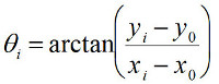 (5)
Note that one should take care to "unwrap" the angle θ, i.e. to add phase jumps of ±π where appropriate. Custom-written code for the fitting and conversion from (x,y) to (r, θ) coordinates is available from the authors upon request. In the FOMT, a time trace in which the bead traces out a circular annulus can be obtained by achieving coarse alignment (cf. step 3.3) and recording the thermal fluctuations of the bead. In the MTT, thermal fluctuations are insufficient to trace out the circular annulus; instead, use a time trace where the magnets are slowly (typically at 0.1 Hz) rotated by several turns to fit the circle using Equations 3-5.
We note that for the MTT, it is important to choose the proper angular tracking approach, i.e. via an angular tracking marker (Figure 1c, Figure 1d, Figure 3a) or via the conversion of (x,y)-positions into angular coordinates (Figure 1d, Figure 2b). While typically the accuracies of the angular tracking from (x,y)-positions and the use of marker beads are comparable, it is important to realize that crosstalk occurs between a bead's fluctuations in (x,y) and in angle, as described in Janssen et al32: thus, angular tracking from (x,y)-positions is only valid provided that the Brownian fluctuations in (x,y) contribute only negligibly to the uncertainty in the angular coordinate, and its proper use of (x,y)-tracking may require tuning of the rotational trap stiffness via adjustment of the position of the side magnet. Typically, the use of higher trap stiffness requires the use of angular tracking using marker beads. The use of marker beads requires an additional attachment step, which may reduce the number of usable tethers (see the attachment protocol in step 1.9). When using the marker bead-based tracking, it is important to select magnetic beads which have a marker bead is attached near the equator for best results.
Significance of the FOMT and MTT Approaches Compared to Existing Methods and Applications
In the above, we have shown how one can, starting from conventional MT, easily modify the magnet configurations to convert the instrument into MTT or FOMT. This straightforward modification, which may be accompanied by the introduction of angular tracking when the use of an angular tracking marker is desired, is an immediate strong point of both configurations, as it permits the user to apply torque, measure torque, or measure twist depending on the experiment at hand. As mentioned in the Introduction, both FOMT and MTT benefit from many of the existing strengths of MT, notably their simplicity, with the MTT in particular also benefiting from the capability of parallel measurements5,6 (these are not as easily achieved in FOMT given the requirement of alignment of the tether with respect to the center of the cylindrical magnet). Notably, MTT and FOMT do not require, in contrast with other techniques, specially nano-fabricated particles22,39,40, complex optical design41, or the introduction of additional beads within the tethered (DNA) molecule42. Such other techniques may nonetheless provide other advantages such as higher temporal resolution27,43,44. Both FOMT and MTT should find future applications in the study of genome processing, as the behavior of molecular motors on DNA is both influenced by and has consequences for the local twist and torque. Additional applications can be found in the emerging field of DNA nanotechnology27 or in the wider field of rotary motors active in biological processing7,45.
| M270 (Rbead = 1.4 µm) | MyOne (Rbead = 0.5 µm) | Ademtech (Rbead = 0.25 µm) | |
| Conventional MT (pair of cubic 5 x 5 x 5 mm3 magnets, 1 mm gap, vertical alignment) | 70 pN | 8 pN | 1.6 pN |
| FOMT or MTT* (stack of three cylindrical magnets, 6 mm diameter, 2 mm diameter gap) | 9 pN | 1 pN | 0.2 pN |
| FOMT or MTT* (stack of three cylindrical magnets, 6 mm diameter, 1 mm diameter gap) | 18 pN | 2 pN | 0.4 pN |
| FOMT or MTT* (stack of three cylindrical magnets with last one flipped, 1 mm diameter gap) | ~50 pN | 9 pN | 1.8 pN |
*The presence of the small side magnet in the MTT has a negligible effect on the stretching force
Table 1. Maximum forces typically achieved for different magnet configurations and bead types.
| Rbead = 1.4 µm | Rbead = 0.5 µm | Rbead = 0.25 µm | |
| Friction coefficient* | 120 pN·nm·sec | 5.5 pN·nm·sec | 0.7 pN·nm·sec |
| Characteristic time scale: FOMT, 10 kbp DNA** | 1200 sec | 55 sec | 7 sec |
| Characteristic time scale: FOMT, 1 kbp DNA | 120 sec | 5.5 sec | 0.7 sec |
| Characteristic time scale: MTT, kq = 100 pN·nm/rad | 1.2 sec | 0.06 sec | 0.007 sec |
| Characteristic time scale: MTT, kq = 1000 pN·nm/rad | 0.12 sec | 0.006 sec = 6 msec | 0.0007 s = 0.7 msec |
*Friction coefficient for rotation about an axis through the "equator" (i.e. the situation shown in Figure 1b), given by 14·p·h·Rbead3, where h is the viscosity of the buffer.
**In the FOMT, the rotational trap stiffness is given by the torsional stiffness of the DNA, kq,DNA = C·kBT/LC, where C is the effective torsional persistence length, assumed to be 80 nm here (which is characteristic of an intermediate force regime, F ~ 1 pN) and LC is the contour length of DNA, 0.34 nm per base pair.
Table 2. Friction coefficients and characteristic time scales for FOMT and MTT.
Disclosures
A patent related to this work has been filed under reference PCT/NL2011/050446.
Acknowledgements
This work was supported by the TU Delft, the Netherlands Organisation for Scientific Research (NWO), the Foundation for Fundamental Research on Matter, and by the European Science Foundation.
Materials
| Name | Company | Catalog Number | Comments |
|---|---|---|---|
| Sandblaster | Great Lake Orthodontics | 190-070 Microetcher II | |
| Nitrocellulose | Life Technologies | LC2001 | |
| Magnetic particle concentrator | Life Technologies | 12002D | |
| Non-magnetic latex beads (0.5 μm radius) | Polysciences | 17010 | |
| Non-magnetic latex beads (1.5 μm radius) | Sanbio | PV05N/2179 | |
| Antidigoxigenin | Roche | 11 214 667 001 | |
| Streptavidin-coated superparamagnetic beads (0.25 μm radius) | Ademtech | 3150 | |
| Streptavidin-coated superparamagnetic beads (0.5 μm radius, “MyOne”) | Life Technologies | 650.01 | |
| Streptavidin-coated superparamagnetic beads (1.4 μm radius, “M270”) | Life Technologies | 653.05 | |
| Biotin-coated latex beads (0.5 μm radius) | Life Technologies | F-8768 | |
| Cubic magnets for conventional tweezers | Supermagnete | W-05-N50-G | |
| Cylindrical magnet for MTT and FOMT | Supermagnete | R-06-02-02G | |
| Side magnet for MTT | Supermagnete | S-04-07-N | |
| Linear stage | Physik Instrumente | M-126.PD | |
| Rotary stage | Physik Instrumente | C-150 | |
| High-resolution automated sample stage | Physik Instrumente | P-733.2D | |
| Software for coding analysis routines | The Mathworks | MATLAB | custom-written routines are available from the authors |
References
- Strick, T. R., Allemand, J. F., Bensimon, D., Bensimon, A., Croquette, V. The elasticity of a single supercoiled DNA molecule. Science. 271, 1835-1837 (1996).
- Bustamante, C., Bryant, Z., Smith, S. B. Ten years of tension: single-molecule DNA mechanics. Nature. 421, 423-427 (2003).
- Neuman, K. C., Nagy, A. Single-molecule force spectroscopy: optical tweezers, magnetic tweezers and atomic force microscopy. Nature methods. 5, 491-505 (2008).
- Lipfert, J., Hao, X., Dekker, N. H. Quantitative modeling and optimization of magnetic tweezers. Biophysical journal. 96, 5040-5049 (2009).
- Ribeck, N., Saleh, O. A. Multiplexed single-molecule measurements with magnetic tweezers. The Review of scientific instruments. 79, (2008).
- De Vlaminck, I., et al. Highly parallel magnetic tweezers by targeted DNA tethering. Nano letters. 11, 5489-5493 (2011).
- Koster, D. A., Crut, A., Shuman, S., Bjornsti, M. A., Dekker, N. H. Cellular strategies for regulating DNA supercoiling: a single-molecule perspective. Cell. 142, 519-530 (2010).
- Dulin, D., Lipfert, J., Moolman, M. C., Dekker, N. H. Studying genomic processes at the single-molecule level: introducing the tools and applications. Nature reviews. Genetics. 14, 9-22 (2013).
- Ajjan, R., et al. Common variation in the C-terminal region of the fibrinogen beta-chain: effects on fibrin structure, fibrinolysis and clot rigidity. Blood. 111, 643-650 (2008).
- Mierke, C. T., et al. Mechano-coupling and regulation of contractility by the vinculin tail domain. Biophysical journal. 94, 661-670 (2008).
- Shang, H., Lee, G. U. Magnetic tweezers measurement of the bond lifetime-force behavior of the IgG-protein A specific molecular interaction. Journal of the American Chemical Society. 129, 6640-6646 (2007).
- Shang, H. K. P., et al. The application of magnetic force differentiation for the measurement of the affinity of peptide libraries. J Magn Magn Mater. 293, 382-388 (2005).
- Lee, G. U., Metzger, S., Natesan, M., Yanavich, C., Dufrene, Y. F. Implementation of force differentiation in the immunoassay. Analytical biochemistry. 287, 261-271 (2000).
- Smith, A. S., Sengupta, K., Goennenwein, S., Seifert, U., Sackmann, E. Force-induced growth of adhesion domains is controlled by receptor mobility. Proceedings of the National Academy of Sciences of the United States of America. 105, 6906-6911 (2008).
- Kanger, J. S., Subramaniam, V., van Driel, R. Intracellular manipulation of chromatin using magnetic nanoparticles. Chromosome research : an international journal on the molecular, supramolecular and evolutionary aspects of chromosome biology. 16, 511-522 (2008).
- Tanase, M., Biais, N., Sheetz, M. Magnetic tweezers in cell biology. Methods in cell biology. 83, 473-493 (2007).
- Bausch, A. R., Moller, W., Sackmann, E. Measurement of local viscoelasticity and forces in living cells by magnetic tweezers. Biophysical journal. 76, 573-579 (1999).
- Lipfert, J., Koster, D. A., Vilfan, I. D., Hage, S., Dekker, N. H. Single-molecule magnetic tweezers studies of type IB topoisomerases. Methods Mol Biol. 582, 71-89 (2009).
- Vilfan, I. D., Lipfert, J., Koster, D. A., Lemay, S. G., Dekker, N. H. Handbook of Single-Molecule Biophysics. Hinterdorder, P., van Oijen, A. , Springer. (2009).
- Gosse, C., Croquette, V. Magnetic tweezers: micromanipulation and force measurement at the molecular level. Biophysical journal. 82, 3314-3329 (2002).
- Lipfert, J., Wiggin, M., Kerssemakers, J. W., Pedaci, F., Dekker, N. H. Freely orbiting magnetic tweezers to directly monitor changes in the twist of nucleic acids. Nature communications. 2, 439(2011).
- Celedon, A., et al. Magnetic tweezers measurement of single molecule torque. Nano letters. 9, 1720-1725 (2009).
- Lipfert, J., Kerssemakers, J. J., Rojer, M., Dekker, N. H. A method to track rotational motion for use in single-molecule biophysics. The Review of scientific instruments. 82, (2011).
- Lipfert, J., Kerssemakers, J. W., Jager, T., Dekker, N. H. Magnetic torque tweezers: measuring torsional stiffness in DNA and RecA-DNA filaments. Nature. 7, 977-980 (2010).
- Mosconi, F., Allemand, J. F., Bensimon, D., Croquette, V. Measurement of the torque on a single stretched and twisted DNA using magnetic tweezers. Physical review letters. , 102(2009).
- Mosconi, F., Allemand, J. F., Croquette, V. Soft magnetic tweezers: A proof of principle. Review of Scientific Instruments. 82 (12), (2011).
- Kauert, D. J., Kurth, T., Liedl, T., Seidel, R. Direct mechanical measurements reveal the material properties of three-dimensional DNA origami. Nano letters. 11, 5558-5563 (2011).
- Velthuis, A., Kerssemakers, J. W. J., Lipfert, J., Dekker, N. H. Quantitative Guidelines for Force Calibration through Spectral Analysis of Magnetic Tweezers Data. Biophysical journal. 99, 1292-1302 (2010).
- Lansdorp, B. M., Saleh, O. A. Power spectrum and Allan variance methods for calibrating single-molecule video-tracking instruments. The Review of scientific instruments. 83, (2012).
- Bouchiat, C., et al. Estimating the persistence length of a worm-like chain molecule from force-extension measurements. Biophysical journal. 76, 409-413 (1999).
- Lee, M., Lipfert, J., Sanchez, H., Wyman, C., Dekker, N. H. Structural and torsional properties of the RAD51-dsDNA nucleoprotein filament. Nucleic acids research. 41, (2013).
- Janssen, X. J., et al. Electromagnetic torque tweezers: a versatile approach for measurement of single-molecule twist and torque. Nano letters. 12, 3634-3639 (2012).
- Baumann, C. G., Smith, S. B., Bloomfield, V. A., Bustamante, C. Ionic effects on the elasticity of single DNA molecules. Proc Natl Acad Sci U S A. 94, 6185-6190 (1997).
- Lipfert, J., Wiggin, M., Kerssemakers, J. W., Pedaci, F., Dekker, N. H. Freely orbiting magnetic tweezers to directly monitor changes in the twist of nucleic acids. Nat Commun. 2, 439(2011).
- Cheezum, M. K., Walker, W. F., Guilford, W. H. Quantitative comparison of algorithms for tracking single fluorescent particles. Biophys. J. 81, 2378-2388 (2001).
- Gelles, J., Schnapp, B. J., Sheetz, M. P. Tracking kinesin-driven movements with nanometre-scale precision. Nature. 331, 450-453 (1988).
- Loenhout, M. T., Kerssemakers, J. W., De Vlaminck, I., Dekker, C. Non-bias-limited tracking of spherical particles, enabling nanometer resolution at low magnification. Biophysical journal. 102, 2362-2371 (2012).
- Kim, K., Saleh, O. A. A high-resolution magnetic tweezer for single-molecule measurements. Nucleic acids research. 37, 136(2009).
- Deufel, C., Forth, S., Simmons, C. R., Dejgosha, S., Wang, M. D. Nanofabricated quartz cylinders for angular trapping: DNA supercoiling torque detection. Nature methods. 4, 223-225 (2007).
- Huang, Z., Pedaci, F., van Oene, M., Wiggin, M. J., Dekker, N. H. Electron beam fabrication of birefringent microcylinders. ACS nano. 5, 1418-1427 (2011).
- La Porta, A., Wang, M. D. Optical torque wrench: angular trapping, rotation, and torque detection of quartz microparticles. Physical review letters. 92, (2004).
- Gore, J., et al. DNA overwinds when stretched. Nature. 442, 836-839 (2006).
- Bryant, Z., Oberstrass, F. C., Basu, A. Recent developments in single-molecule DNA mechanics. Curr Opin Struct Biol. 22, 304-312 (2012).
- Oberstrass, F. C., Fernandes, L. E., Bryant, Z. Torque measurements reveal sequence-specific cooperative transitions in supercoiled DNA. Proceedings of the National Academy of Sciences of the United States of America. 109, 6106-6111 (2012).
- Forth, S., Sheinin, M. Y., Inman, J., Wang, M. D. Torque measurement at the single-molecule level. Annu Rev Biophys. 42, 583-604 (2013).
Reprints and Permissions
