This protocol describes a procedure for constructing carbon fiber microelectrode arrays for chronic and acute in vivo electrophysiological recordings in mouse (Mus musculus) and ferret (Mustela putorius furo) from multiple brain regions. Each step, following the purchase of raw carbon fibers to microelectrode array implantation, is described in detail, with emphasis on microelectrode array construction.
Method Article
Construction and Implementation of Carbon Fiber Microelectrode Arrays for Chronic and Acute In Vivo Recordings
* These authors contributed equally
In This Article
Summary
Abstract
Multichannel electrode arrays offer insight into the working brain and serve to elucidate neural processes at the single-cell and circuit levels. Development of these tools is crucial for understanding complex behaviors and cognition and for advancing clinical applications. However, it remains a challenge to densely record from cell populations stably and continuously over long time periods. Many popular electrodes, such as tetrodes and silicon arrays, feature large cross-diameters that produce damage upon insertion and elicit chronic reactive tissue responses associated with neuronal death, hindering the recording of stable, continuous neural activity. In addition, most wire bundles exhibit broad spacing between channels, precluding simultaneous recording from a large number of cells clustered in a small area. The carbon fiber microelectrode arrays described in this protocol offer an accessible solution to these concerns. The study provides a detailed method for fabricating carbon fiber microelectrode arrays that can be used for both acute and chronic recordings in vivo. The physical properties of these electrodes make them ideal for stable and continuous long-term recordings at high cell densities, enabling the researcher to make robust, unambiguous recordings from single units across months.
Introduction
Electrodes and electrode arrays are valuable tools for understanding how the brain processes information at the neuronal level. While electrophysiological recordings have been achievable for over two centuries1, it is still not possible to simultaneously measure the activity of entire neural circuits at the spatial and temporal resolution required to capture the spiking of individual neurons. Although non-invasive methods, such as electroencephalography2, positron emission topography3, and functional magnetic resonance imaging4 allow for whole-brain measurements, they cannot achieve the spatial and temporal resolution necessary for resolving the activity of neural circuits2,5. In contrast, imaging methods such as optical imaging using voltage-sensitive dyes or genetically encoded calcium indicators can achieve single-unit spatial resolution, but they pose issues such as low temporal resolution and poor selectivity3,4,5,6. Electrical recordings are a powerful alternative to these methods. Recording electrodes provide unparalleled temporal resolution and allow the user to make measurements with spike-time precision in any region of the brain7. Additionally, chronically implanted multielectrode arrays (MEAs) enable large-scale (tens to hundreds of cells), single-cell recordings in behaving animals over a period of days to months8,9. However, silicon probes that record at higher densities have a large footprint and are highly invasive, and chronically implanted arrays often generate an inflammation response, tissue encapsulation, and neuronal death10,11,12,13.
The limitations of existing electrodes have resulted in recent innovations that allow for stable, high-resolution, long-term recordings. Typical electrodes consist of a metallic conductor, such as tungsten or platinum-iridium, or are silicon- or polymer-based. While metal-based microwire arrays can maintain long-term, stable recordings, they have a much larger footprint, with a single wire's diameter ranging from 10-200 µm14. In contrast, silicon-based electrode arrays yield recordings with high spatial resolution, but due to their relatively rigid design, they are typically unable to maintain the signal and record from the same neurons over many months15. Recent developments in silicon-based arrays have resulted in electrodes that can reliably perform chronic recordings, but these arrays cannot be used to record from deep brain regions in larger animals and are intended for linear recordings9. Advances in polymer arrays have resulted in increased flexibility and recording stability of single units and offer the potential for high-density recordings in the near future but with limited availability at present8,16,17. Carbon fibers allow for high-density recordings with off-the-shelf materials that are described here.
Carbon fiber recording microelectrodes have been used for decades, with the first carbon fiber electrodes consisting of a single carbon-fiber inserted into a glass micropipette. These microelectrodes were used for single-unit extracellular recordings, and although the signal-to-noise ratio was comparable to the best tungsten-in-glass microelectrodes, they were advantageous due to their flexibility, lower impedance values, and simplicity to manufacture18,19. Efforts to develop carbon fiber electrode arrays have recently accelerated due to the biosensing capabilities of carbon fibers. In addition to their increased biocompatibility and exceptional electrical conductivity, they feature a unique set of properties, including high-temperature resistance, low relative density, high tensile strength, low bending stiffness, high detection sensitivity, and a small cross-sectional area10,12. All of these properties have motivated the development of carbon fiber microelectrode arrays (CFEAs) that facilitate chronic, stable, high-yield recordings of single neurons. Such CFEAs can now be crafted by hand20,21 (Figure 1), yielding microelectrode arrays that can hold single neurons over months. Described here is an accessible construction process for CFEAs that has been adapted in two ways for acute and chronic recordings of individual neurons in two species.
Protocol
All experimental procedures were approved by the Brandeis University or Washington University Animal Care and Use Committee. Data shown were collected from one female ferret and one male mouse.
1. Preparation of carbon fibers and tools
- Preparation of commercial carbon fibers
- Cut 8 cm strips from the epoxy-sized fiber bundle. Lay the strips parallel in a crucible and bake in a kiln at 400 °C for 6 h to remove the epoxy from commercial fibers. Then, store the baked fibers in a standard Petri dish or a conical tube.
NOTE: Fibers with a diameter of 7 µm were used. Other groups have used 4 µm fibers20,21. - Prepare cassettes for holding individual fibers. Use a 3D printer or laser cutter to create the cassettes and the associated cassette holder (see Figure 2).
- Load the fibers onto the cassettes. Start by laying a piece of double-sided tape on the two long sides of the cassette, aligning the edge of the tape with the inner edge of the cassette. Separate individual fibers from the baked bundle and lay them parallel with the short side of the cassette, keeping 2-3 mm between fibers. Ensure to fit 20-30 fibers on each cassette. Seal the fibers in place by laying clear tape over the double-stick tape. Place the filled cassettes in the cassette holder.
NOTE: For an experienced builder, filling one cassette of fibers will take ~1 h. For the novice builder, this process will likely take ~1.5-3 h. There are ten cassettes to a box, and two cassette holders can fit in the parylene deposition chamber. - Coat the individual fibers with parylene C using a commercial vacuum deposition chamber. A single run is needed for coating. Measure out 2.3 g of parylene for each run. Two cassette holders fit in the chamber at a time. The coating procedure takes ~2 h per run.
NOTE: A measurement of 2.3 g of parylene C provides an approximate 1 µm of coating. Coated fibers can be stored indefinitely.
- Cut 8 cm strips from the epoxy-sized fiber bundle. Lay the strips parallel in a crucible and bake in a kiln at 400 °C for 6 h to remove the epoxy from commercial fibers. Then, store the baked fibers in a standard Petri dish or a conical tube.
- Preparation of carbon fiber manipulation tool
- Wrap a small piece of flexible adhesive film around a 30 G needle, forming a sharp but flexible point with the adhesive film.
NOTE: Wrapping a needle tip with parafilm, and stretching the parafilm in doing so, creates a mild adhesive effect that allows the user to pick up and maneuver individual fibers.
- Wrap a small piece of flexible adhesive film around a 30 G needle, forming a sharp but flexible point with the adhesive film.
2. Design and fabrication
- Select the appropriate jig design necessary based on the specifications of the electrode to be built. This will be based on the number of channels needed, along with any design additions.
NOTE: Jig refers to the 3D printed block that provides an anchor for electrodes and electrical connections. - Create or alter the specific design of the jig using computer-aided design (CAD) software.
- Use a 3D printing company or the institutional maker lab to print the jigs using a high-resolution SLA 3D printer.
3. Assembling the carbon fiber microelectrode array (CFEA)
NOTE: This step takes ~2 h for an experienced builder and ~6 h for a novice builder. Perform all CFEA assembly steps and fiber bundling steps under a 10x stereo microscope. Complete assembling the CFEA in an environment with minimal air movement, as this may disturb the building process.
- Choose the appropriate jig needed to build the electrode desired.
- Using metal wire cutters, cut two pieces of tungsten wire of diameter 0.003 in (76.2 µm), about 7 cm in length.
- Feed each wire through the appropriate channel on the connector end of the jig (GND and REF). Feed enough through until the two ends are equal in length, and then twist them together to secure them on the jig.
NOTE: For the 16-channel acute design, ensure that the metal wire fits within the ridge in the jig.- Apply UV-cured dental cement to secure the wire. Ensure not to get any dental cement within the open channel that the wire is fed through.
NOTE: The user should wear UV filtering eye protection during all UV-related procedures to prevent potential eye damage. Many UV curing wands have built-in viewing filters. - Using the UV curing wand, cure the dental cement for 20 s.
- Secure the jig in the jewelry vise by one of the arms of the jig. Orient the jig so that one of the side-faces is parallel to the ground.
- Orient the jig and vise under the microscope so that the connector end, the basin, and the funnel tip are visible. Orient the jig so the funnel is pointing away from the user and the connector end is facing toward the user.
- Gather the carbon fiber tools and a sharp-tipped 25 G needle.
- Place a cassette with parylene-C-coated fibers on a white sheet of paper, tape side up so that the fibers are not directly on the paper.
- Use the 25 G needle to cut a single carbon-fiber out of the cassette. Do this by sliding the tip of the needle against the cassette where the fiber to be removed emerges from.
- If building using half fibers, cut one end of the fiber as described above. Orient the fiber so that it is straight, and using the needle, cut the fiber in half by cutting the fiber against the paper. In order to cut the other half, which is still connected to the cassette, hold the free tip of the fiber with the carbon fiber tool that was made previously, and then use the needle to cut the fiber still connected to the cassette as described above.
- If building using full fibers, cut one end of the fiber as described above. Use the carbon fiber tool previously made and hold the free end of the fiber that was just cut. Using the needle, cut the other end of the fiber away from the cassette.
- Pick up the carbon fiber using the carbon fiber tool previously made. Pick up the fiber so that one end has about 1 cm of length from the tool.
- Use the carbon fiber tool with the fiber attached and feed the shorter end of the fiber through the funnel piece from the middle basin of the jig. Use a microscope to visualize.
- Continue to feed the fiber through the jig funnel until most of the length of the fiber is through (see Figure 3A).
- Feed the back portion of the fiber through an available channel using the carbon fiber tool previously made. Feed the fiber through the back until about 5 mm of fiber is sticking out the back. Cut to size if necessary (see Figure 3B).
NOTE: Do not feed fibers into channels that contain the metal wires.
- Fill the remainder of the channels with fibers on one side of the jig, following the directions given above.
NOTE: When feeding fibers into the funnel, feed half the fibers into each division of the funnel, with the right half of the channels in the right division and the left half of the channels in the left division. When the fibers are in close contact within the funnel, there is unfavorable friction between fibers that leads to existing fibers either pulled loose or broken while feeding new fibers into the jig. This division into four sections provides some relief, as the fibers are kept in smaller bundles until a later step. - Use a standard spark wheel lighter and quickly pass the flame over the exposed fibers at the connector end. Ensure that the insulation of all the fibers is removed at the ends (see Figure 3C).
NOTE: The portion of the fibers that were exposed to the flame should appear to be slightly thinner than the rest of the fiber. - Feed the flamed fiber through the jig so that the portion of the fiber exposed to the flame is now within the channel. Make sure that no fibers are sticking out the back of the jig (see Figure 3D).
NOTE: Use the carbon fiber tool to grasp the fiber from within the basin and feed the flamed fiber through the jig. Do not touch the portion of the fibers exposed to the flame, as this portion is more fragile. - Apply UV-cured dental cement to the fibers in the basin of the jig. Fill the entire basin to cover the openings of the channels and the opening of the funnel (see Figure 3E).
- Use the UV light and cure the dental cement for 20 s. Cure for an additional 20 s if dental cement is not completely cured.
NOTE: Ensure that the dental cement does not travel inside the channels.
- Use the UV light and cure the dental cement for 20 s. Cure for an additional 20 s if dental cement is not completely cured.
- Remove the jig from the vise, flip it over, and secure the jig in the vise as previously secured. Make sure that the side containing the fibers is now face down.
- Fill in the empty side of the jig with carbon fibers exactly as described above.
- Once all of the channels have fibers, and the fibers are secured with dental cement, remove the jig from the vise and orient the jig so that the funnel is pointing down. Secure the jig in the vise so that the connector end is pointing up.
- Gather a sharp-tipped 25 G needle, a 1 mL syringe, silver conductive paint, cotton-tipped applicators, paint thinner, tissue wipes, and the appropriate headstage connector.
NOTE: Ensure the silver conductive paint is well mixed and is a homogenous solution. Do not let the paint dry out. - Draw up 0.3 mL of silver paint into the 1 mL syringe, and then attach the sharp-tipped 25 G needle.
- Carefully insert the needle into one channel until stopped by the dental cement. Slowly depress the syringe while removing the needle from the channel to fill the channel with paint (see Figure 3E).
- Wipe any paint off the needle, and then continue to the next channel.
- Fill all the channels with paint.
NOTE: Additional passes into the channels may be necessary as the paint sets in the channels for the first several minutes.
- Fill all the channels with paint.
- Dip a cotton-tipped applicator in the paint thinner, and then clean the base of the jig of any paint on the surface. A few cotton-tipped applicators may be necessary for this.
NOTE: Cotton-tipped applicators not dipped in paint thinner may also be useful to clean off the jig. - Insert the headstage connector in the proper orientation by aligning the pins with the channels. Ensure that the headstage connector is sitting straight upright and is as flush to the jig as possible (see Figure 3F).
- Allow the jig to cure for 24 h.
- Secure the headstage connector to the jig using UV cured dental cement by applying dental cement along the edge where the headstage connector meets the jig. UV cure using a UV light for 20 s.
- Apply UV-cured dental cement to secure the wire. Ensure not to get any dental cement within the open channel that the wire is fed through.
4. Fiber bundle packaging
NOTE: It takes approximately 30 min to perform this step. Complete this step for the electrodes used in animal models with a thick layer of pia mater. Reinforce the fiber bundle to minimize bending. In mouse procedures, this step may not be necessary.
- Bring the bundle of fibers together in a single shaft using water tension. Use a transfer pipette to run a drop of water from the funnel tip to the bundle tip while the electrode is secured upright in a vise.
- Start with applying a layer of dental cement about 1.5 mm thick around the bundle at the funnel tip. Cure the dental cement with 20 s of UV light.
NOTE: For cortical recordings, no further packaging is needed. For deeper brain regions, secure a guide tube around the bundle. - Construction of guide tube and insertion of the bundle into the guide tube
- Measure and cut the desired length of polyimide tubing. Ensure that the length of polyimide tubing leaves 2 mm of carbon fiber tips free. Measure and cut a piece of 30 G metal tubing 2 mm shorter than the polyimide tubing. Use a rotary tool to remove any sharp edges on the metal tubing. Insert the polyimide tubing inside of the metal tubing.
- Position the electrode in a vise with the carbon fiber bundle pointing up. Secure the assembled tubing to a micromanipulator and, using a microscope, carefully lower it over the fiber bundle. Secure the tubing to the existing dental cement base using an additional layer of dental cement. Cure the dental cement with 20 s of UV light.
NOTE: The construction process can be paused here.
5. Electrode tip preparation
NOTE: It takes approximately 30 min per array to perform this step.
- Cut electrodes to the desired length.
- In preparation for cutting the electrode tip, stack sticky notes to build a platform approximately 1.5 mm high. Measure, from the edge of the platform, the desired electrode length and mark this distance. The platform will act as a guide for cutting.
- Lower the electrode into a beaker of deionized or distilled water until the funnel tip is fully submerged, tip first, and held normal to the surface. Bring the individual carbon fibers together by removing the electrode from the water. Surface tension will bring the bundle(s) together. Allow the electrode to air dry for 30 min.
- Attach the #10 scalpel blade to the handle. Freeze the scalpel and electrode by placing them in a -18 °C freezer for at least 5 min.
- Lay the electrode so that the fibers lay flush on the surface of the guide (prepared in step 5.1.1). Cut the fibers to the desired length with the scalpel, using a rolling motion. Complete this step quickly to ensure the electrode and scalpel are still frozen (see Figure 3G).
- Inject positive current to reduce the impedance of electrode tips.
- Attach the electrode to multielectrode impedance tester using the appropriate adapter (see Table of Materials). Lower electrode tip ~2 mm into a microcentrifuge tube of 0.1 M phosphate-buffered saline (PBS). Insert grounding wire into the microcentrifuge tube.
- Inject current with the chosen amplitude and duration.
NOTE: This step is intended to reduce the impedance values at the tip of the CFEA. In this study, the following parameters were entered into the electroplating software graphical user interface: Current: 0.100 µA; Duration: 10 s; Pause: 1 s. This process can be repeated as necessary, per channel, until electrode impedances meet the desired values (see Figure 4C). - Once the impedance values are as desired, rinse the fibers in deionized or distilled water to clean.
- Electroplate in the gold plating solution.
NOTE: This step should be done shortly before implantation (same day).
CAUTION: Some of the chemicals used in the preparation of CFEA tips are corrosive, including the gold plating solution. Consult the SDS prior to use and determine the appropriate precautionary measures to take in order to handle the solution safely.
NOTE: To provide stiffness to the fiber bundle, the user may create a gold plating solution by first solubilizing PEG8000 in deionized or distilled water at 1 mg/mL. Then, combine 625 µL solubilized PEG8000 and 375 µL gold plating solution and vortex solution for 10 s to mix. The PEG8000 will dissolve after the insertion of fibers in the brain.- Lower the electrode bundle tip ~2 mm into the microcentrifuge tube of the plating mixture. Insert the grounding wire into the microcentrifuge tube.
- Set appropriate parameters for electroplating. In this study, the following parameters were entered into the electroplating software graphical user interface: Current: -0.05 µA; Duration: 30 s; Pause: 5 s.
- Rinse the fibers thoroughly with deionized or distilled water. At this time, measure the impedance values again if desired.
6. Insertion in the brain: Survival surgery, mouse (Mus musculus) and non-survival surgery, ferret (Mustela putorius furo)
NOTE: Surgical procedures should follow standard protocol in compliance with IACUC. For detailed information see Ma et al.22 for survival surgery protocol and Popovic et al.23 for non-survival surgery protocol. Follow the aseptic surgical procedures per the ASC guidelines for survival surgery in rodent species. These include autoclaving all surgical tools and materials at 135 °C for 15 min and treating the stereotaxic apparatus and surgical area with 70% ethanol. Use sterile surgical gloves, a disposable gown, and face mask during the procedure.
- Survival surgery, mouse (Mus musculus).
- Anesthetize the mice with 2.5% isoflurane in an induction box for ~1 min, until the breathing rate reaches 55-65 breaths/min. Then, administer 2.0% isoflurane through a nose cone to maintain anesthesia. Apply vet ointment to both eyes to prevent corneal damage. Perform a toe pinch to verify the proper degree of anesthesia.
- After verification, follow survival surgery procedures detailed in Ma et al.22. Monitor the respiratory rate and maintain it at 60 breaths/min. Maintain the body temperature at 37 °C using a thermostatically controlled heating pad. See steps 6.3-6.5 (detailed below) for instructions on preparing the skull for the craniotomy, durotomy, and electrode implantation.
- Following the surgery, return the mice to a recovery cage, equipped with a 37 °C heating pad, isolated from other animals.
- Cover the surgical wounds in the antibiotic ointment. Monitor the animals until they regain sufficient consciousness to maintain sternal recumbency and allow them to recover for a 2-5-day period. House them singly and monitor continuously for signs of infection or discomfort. Give the animals one dose of buprenorphine 72 h sustained-release (0.5-1.0 mg/kg) on the day of the surgery as an analgesic.
- Non-survival surgery, ferret (Mustela putorius furo)
- Anesthetize the ferret initially with ketamine (20 mg/kg, i.m.), and then ventilate with 1.0%-2.0% isoflurane in a 2:1 mixture of nitrous oxide and oxygen through a mask. Perform a toe pinch to verify the proper degree of anesthesia.
- After verification, follow non-survival surgery procedures detailed in Popovic et al.23. Perform a tracheostomy and ventilate the animals with 1.0%-2.0% of isoflurane in a 2:1 mixture of nitrous oxide and oxygen. Apply vet ointment to both the eyes to prevent corneal damage.
- Maintain the body temperature at 37 °C using a thermostatically controlled heating pad. Monitor the heart rate, end-tidal CO2 levels, and respiration rate. Keep the respiration rate within the appropriate physiological range (3.5%-4.0%). See steps 6.3-6.5 (detailed below) for instructions on preparing the skull for the craniotomy, durotomy, and electrode implantation.
- Continuously monitor the animal's ECG to ensure adequate anesthesia and increase the percentage of isoflurane if the ECG indicates any distress.
- At the completion of the experiment, administer 1 mL of pentobarbital sodium and phenytoin sodium solution to the ferret and monitor until the heart rate and end-tidal CO2 measures 0.
- Preparation of the skull
- Using a 0.8 mm drill burr, drill a single 4 mm x 4 mm craniotomy at the desired location for implantation. For mouse, drill an additional burr hole at a contralateral site for stainless-steel ground screw insertion.
NOTE: Do not perform a durotomy until the electrode is ready for implantation. - Establish a ground/reference. In acute ferret experiments, use an 18 G needle to pierce through the skin and the layer of muscle surrounding the skull on the side of the animal's head opposite from the craniotomy. Insert the wire end of the Ag/Cl reference electrode into the tip of the needle, and then retract the needle from the muscle/skin so that the pellet is now sitting securely between the muscle and skull. In the mouse, wrap the silver ground wire around the stainless-steel grounding screw. Secure with UV cured dental cement.
- Attach the electrode to the electrode holder using a thin strip of labeling tape and secure the electrode holder into the micromanipulator. Attach the ground wire to a grounding source via an alligator clip. Attach the reference wire to the reference electrode embedded in the muscle of the animal.
- Using a 0.8 mm drill burr, drill a single 4 mm x 4 mm craniotomy at the desired location for implantation. For mouse, drill an additional burr hole at a contralateral site for stainless-steel ground screw insertion.
- Durotomy and pia penetration
- Remove the dura from the craniotomy using a dura pick.
- Create a small hole in the pia. To do this, insert and withdraw a metal microelectrode (recommended in the ferret). Alternatively, lower the CFEA orthogonal to the surface of the brain to avoid any vasculature. Once this location is determined, raise the electrode and gently nick the surface of the brain at that location with a dura pick, pulling upward with the pick (recommended in mouse).
- Electrode implantation
- Lower the electrode tip to the same location and, in fine mode, begin to drive the electrode into the brain at a rate of ~2 µm/s. Use a microscope to ensure that the electrode is entering smoothly and not bending.
NOTE: If the electrode is not entering smoothly, raise it out of the brain and readjust the angle. If it continues to bend without entering smoothly, adjust the location and repeat the process of nicking the surface of the brain for the new entry location. - Perform the chronic and acute implantation using the following steps.
- For chronic implantation: Cement the electrode in place using UV cured dental cement.
- Close the incision using 5-0 surgical sutures and build the headcap.
- To build up a headcap add additional dental cement around the implant site. Ensure to cover the nose of the jig.
- Pull the skin up and around the headcap. Suture the incision behind the headcap with 5-0 surgical sutures.
- Apply lidocaine cream and antibiotic ointment.
- Stop the anesthetic and follow standard recovery procedures.
- For acute implantation: After lowering the electrode and reaching the desired depth, wait at least 30 min before beginning electrophysiological recording to allow the electrode to settle in place.
- For chronic implantation: Cement the electrode in place using UV cured dental cement.
- Lower the electrode tip to the same location and, in fine mode, begin to drive the electrode into the brain at a rate of ~2 µm/s. Use a microscope to ensure that the electrode is entering smoothly and not bending.
Results
With the completion of this protocol, stable recordings of single-unit spiking activity will be possible. These microelectrode arrays are customizable in material, channel count, and headstage adapter based on the researcher's needs. Electroplating fibers in gold results in decreased impedances suitable for recording (Figure 4 and Figure 5). If the user intends to record chronically, measurements can be made after the animal has recovered from the surgical procedure. Chronic procedures have resulted in stable, single-unit recordings for at least 120 days. A representative recording is shown in Figure 6, illustrating stable 64-channel electrophysiological activity in the retrosplenial cortex of a freely behaving, adult male mouse. If an acute preparation is intended, recordings can begin shortly after implantation (~30 min). This will allow time for the electrode to settle in the brain. Figure 7 provides a representative example of an acute 16-channel CFEA recording acquired from the primary visual cortex of an adult female ferret. Spike sorting in mouse and ferret was performed with spike sorting software (see Table of Materials).
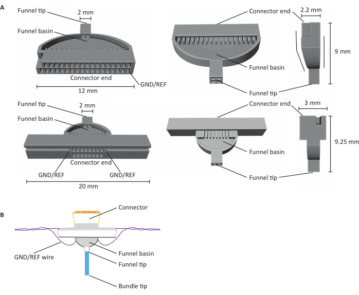
Figure 1: Anatomy of 16- and 32-channel carbon fiber microelectrode arrays (CFEAs). (A) Schematics of 32-channel (top) and 16-channel (bottom) CFEA from three different views. The 16-channel CFEA features an extended design for handling purposes. The 32-channel design features a flat face that allows for two jigs to be combined for a 64-channel CFEA. Both the diagrams have identifying structures labeled with dimensions. The connector end indicates the location of the connector insertion, and GND/REF channels indicate where the grounding wire is inserted. The funnel basin refers to the location that the fibers pass through to be overlaid with UV light-cured dental cement, and the funnel tip signifies the site from where the fibers exit the jig. The funnel tip is divided into quadrants to minimize fibers clinging together and creating damage. The fibers are later pulled into a single bundle with the use of the dental cement. Jigs are 3D printed using SLA resin printers. Diagrams are enlarged to show details. (B) Constructed CFEA. Diagram has identifying structures labeled. The blue bundle tip represents the segment of the carbon fibers that acquire recording measurements. The gray within the funnel basin and surrounding the connector is indicative of UV light-cured dental cement that holds carbon fibers in place in the funnel basin and secures the connector to the jig. The purple wire represents the grounding wire. Please click here to view a larger version of this figure.

Figure 2: Loading of raw carbon fibers into cassettes for parylene C coating. (A) Carbon fibers are loaded onto cartridges overlaid with two strips of double-sided tape (blue). Each cassette is loaded with ~25 fibers. (B) Cassettes are loaded into a laser-cut holder (gray) in preparation for parylene C coating. Each holds ten cassettes. Please click here to view a larger version of this figure.
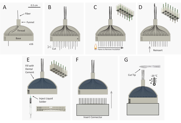
Figure 3: Carbon fiber microelectrode array (CFEA) bundle construction schematic. (A) 16 individual, coated carbon fibers (black) are threaded through the 32-channel 3D-printed jig (gray). (B) Carbon fiber tips are cut with micro-scissors, leaving excess fiber equal to the height of the jig base, extending out of the jig base. (C) A standard plastic spark wheel lighter is quickly passed over the excess fiber to remove parylene C insulation. The top right schematic shows the removal of parylene from 9 of the 12 fibers. (D) Fibers are reinserted into the jig until the fiber end is flush with the base. The top-right schematic shows the reinsertion of 9 fibers with uninsulated (gray) fiber tips housed inside the jig base. The jig is then flipped over and steps A-D are repeated to thread the opposite 16 channels. (E) The jig is filled with dental cement to secure the fibers. Silver print is injected into each well of the jig base. (F) The male connector is inserted into the jig base. (G) CFEA and scalpel are frozen in a -20 °C freezer. The array tip is cut to the desired length, leaving 32 even fibers. Please click here to view a larger version of this figure.
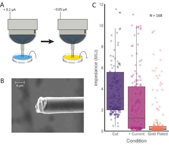
Figure 4: Tip treatment and electroplating. (A) Electrode tips are first placed into 0.1 M PBS, where current is passed through each electrode. The tips are then rinsed and transferred to a gold plating solution, where they are electroplated with the current. (B) SEM images of prepared carbon fiber show gold plating solution concentrated at the tip. Scale bar represents 4 µm. (C) Impedance values from 168 channels after initial cutting (purple; 3.11 MΩ ± 0.42 MΩ, median ± SE, n = 168 fibers), positive current injection (pink; 1.23 MΩ ± 0.36 MΩ, median ± SE, n = 168 fibers), and electroplating (orange; 0.19 MΩ ± 0.15 MΩ, median ± SE, n = 168 fibers) show decreased impedance values after each processing step. Please click here to view a larger version of this figure.
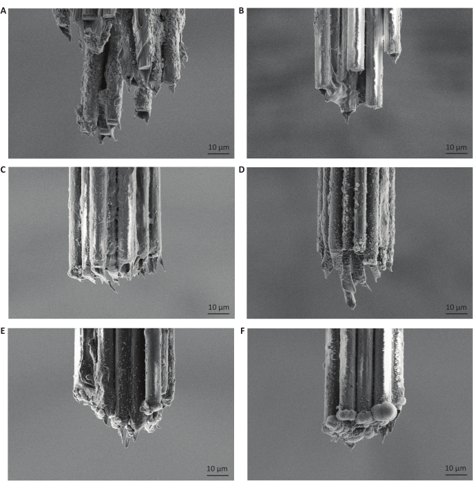
Figure 5: Moderate gold electroplating durations produce small, rounded deposits on carbon fiber bundle tips. The carbon fiber tips pictured are all from different microelectrode arrays, reflecting different durations of injected current for impedance reduction or gold-plating. Images additionally depict the parylene C coating, which insulates the carbon fibers and prevents any acquisition of signal from a location other than the tips of the fibers. (A) Scanning electron microscopy image of carbon fiber tips after freezing and making a single cut with a razor blade. Scale bars represent 10 µm. (B) Same as A but then followed with injection of positive current for 10 s. (C) Same as B but then electroplated with gold for 5 s. (D) Same as B but then electroplated with gold for 15 s. (E) Same as B but then electroplated with gold for 30 s. (F) Same as B but then electroplated with gold for 120 s. We found that electroplating for 30 s at a current of -0.05 µA was optimal for electrophysiological recordings. Please click here to view a larger version of this figure.
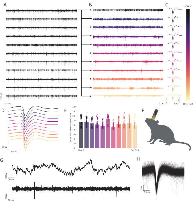
Figure 6: Chronic extracellular recordings in freely behaving mouse retrosplenial cortex with carbon fiber microelectrode arrays show persistent, stable neural activity. (A) Eleven bandpassed voltage traces were recorded simultaneously. Subsequent traces recorded from the first channel (top row) are plotted in B to show durability across time. The remaining ten rows demonstrate the consistency of recording quality and show robust activity across the array. Scale bar to the left of each trace represents a 200 µV potential. (B) Bandpassed data from the same fiber as in the top trace in A, expanded to show robust activity across a 120-day continuous recording. (C) Clustering reveals robust single unit detection over months. Traces represent the average waveform of a continuously observable representative single unit across 120 days, extracted from the fiber plotted in B at each timepoint. (D) Mean, non-normalized spike waveforms from C stacked to demonstrate consistency over time. (E) Carbon fiber recordings demonstrate a stable noise floor over many months. Standard deviation of the noise floor (trace minus spiking activity) in B shows no progressive change in noise. Bars represent mean contamination. Error bars represent standard deviation. (F) Scale drawing of a mouse with a chronically implanted CFEA and headstage. (G) Raw voltage trace (top) 11 months after implantation shows robust LFP. Bandpassed voltage trace (bottom) shows steady neural activity. (H) Mean spike waveform of the neuron recorded on the fiber from C, underlaid by the first 1,000 incidences of spiking activity. Please click here to view a larger version of this figure.
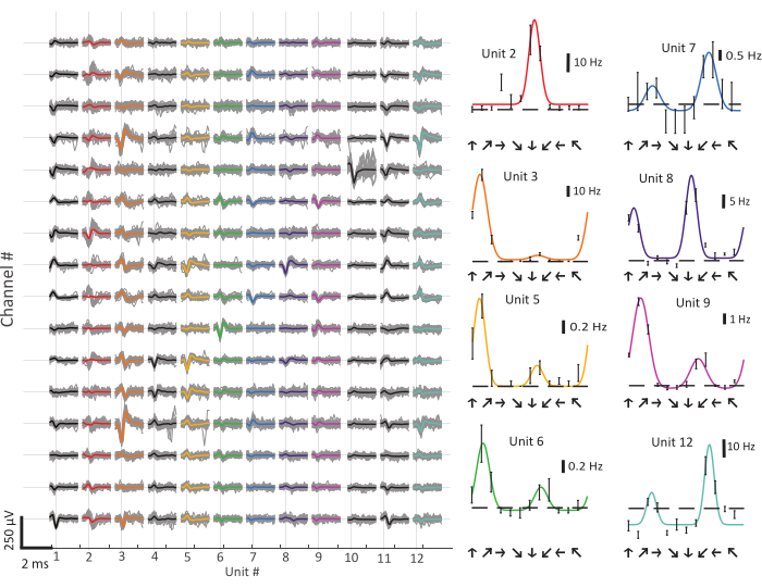
Figure 7: Carbon fiber microelectrode array (CFEA) recordings from the ferret primary visual cortex. (A) Waveforms of spike sorted single units recorded from a 16-channel CFEA. Action potentials from single neurons were often evident on multiple channels at slightly differing amplitudes. (B) Direction tuning curves from selected neurons. Colors correspond to recorded units in A. Arrows indicate the direction of stimulus movement. Scale bars indicate the response rate. Error bars indicate the mean response with standard error. The horizontal dashed line represents the same cell's spontaneous firing rate during exposure to a blank screen. Please click here to view a larger version of this figure.
Discussion
This protocol describes each step necessary for constructing a functional CFEA for both acute and chronic use. The process described is customizable to the researcher's needs, making it an accessible and inexpensive option for monitoring single neurons over months. The protocol demonstrates the feasibility of recording both robust single-unit activity within minutes of implantation in an anesthetized animal, and across four months in an awake, behaving animal, illustrating the potential of these CFEAs to study short-term and long-term changes in neural responses.
The steps of the protocol described have been thoroughly tested and improved upon over time to yield an efficient procedure that can be completed quickly, at a low marginal cost (<$100.00), with the capability of recording unambiguous single units, densely and stably over months. The construction steps can be completed in less than one day and will produce electrophysiological signals that are comparable to any leading commercial array. The CFEAs also have a much smaller footprint (16-channel bundle of fibers has a diameter of ~26 µm) than similar commercial arrays, and their biocompatibility makes them suitable for long-term use13. Importantly, there are several critical steps and instructions that must be followed in order to produce a functioning CFEA with comparable performance.
Due to the fragility of the carbon fibers, they must be handled with utmost care. Handling them with sharp forceps or other tools may result in breakage of the fibers. Additionally, it is important to construct the CFEAs in a space with limited air movement so that the fibers do not blow away. When flaming the back portion of the fibers, the lighter only needs to be moved in a back-and-forth motion very briefly, for approximately 1 s. The steps following this removal of insulation are crucial for constructing an electrode with working channels. The flamed tips should be fed into the jig without any additional contact. Then, when filling the basin with dental cement, it is important that the cement is carefully applied and completely fills the channels and funnel basin, closing off the openings without filling them. The dental cement should then be completely cured with UV light before proceeding. Once this is complete, silver paint should be injected into each channel until completely filled but not spilling out. This is the most variable step in the process. Any over-filling can produce crosstalk between channels, and insufficient filling can result in a connection failure. If unable to inject silver paint using a 25 G needle, it is likely that the solution is too viscous and, in this case, a small amount of paint thinner can be added to create a more fluid solution. Once all the channels are filled, and the headstage connector is inserted, it is important to allow the array to cure for 24 h prior to securing the connector with dental cement. We found that failure to do so lowered the number of connected channels. Applying a generous amount of dental cement is also important so that the connector does not disconnect when interfacing with the signal acquisition system. If they become detached, it is possible to attempt reconnection with the repeated filling of channels with silver paint, but the user should test the impedance values of the CFEA to assess the number of connected channels. Allowing the dental cement to cure overnight also serves to prevent potential detachment.
Measuring the impedance of the electrode will provide an accurate estimation of connected channels. This can be done after submerging the ground and reference wires and the carbon fiber tips in PBS. We have observed that a high impedance (>15 MΩ) is indicative of an open, unconnected channel. Prior to injecting current and electroplating, a connected channel can have a range of impedance values that should significantly decrease with this process. The average number of connected channels (impedance < 4 MΩ after current injection) per 16-channel electrode was 12.96 ± 2.74 (mean ± SD; N = 48 electrodes). A number of electroplating times were tested, and 30 s produced superior signal isolation among the recording sites (Figure 5). While it has been well established that PEDOT-pTS12,24,25,26 and PEDOT-TFB21 provide reliable options for preparing carbon fiber recording sites, we found that plating with gold, a proven and dependable method for electroplating electrodes for chronic implantation27,28, increased the ease of implantation and prevented the electrode tips from clumping together. In producing final impedance values of less than 0.2 MΩ on average, this method proves comparable to values achieved using PEDOT-TFB21 and PEDOT-pTS26.
When implanting the microelectrode array, it is important to visually follow the insertion of the carbon fiber tips under the microscope. Successful insertion should be apparent, with no bending of the fibers. If the fibers appear to be buckling, it is unlikely that they will successfully enter the brain. In this case, the angle of the probe should be adjusted for a second attempt. This process can continue until the insertion of the probe is successful. Once the electrode is at the desired depth, we have found that waiting at least 30 min will allow the probe to settle for optimal signal acquisition (acute recordings).
The CFEAs described, in addition to their small footprint and biocompatibility, offer a robust, customizable alternative to commercial arrays due to their ease of construction and low cost. The greatest limitation to the CFEAs detailed in this protocol is their scalability. Due to the manual nature of their construction, scaling up to designs with hundreds of recording sites may not be practical. Additionally, advances in microelectrode array fabrication using nanotechnology will enable larger-scale population recordings than the methods described here. However, this protocol delivers CFEA accessibility to labs interested in benchtop fabrication of carbon fiber electrodes. We observed no loss of stability or decreased robustness in spike amplitude over the duration of the 120-day chronic experiments, as indicated by a representative single channel typical of our observations on that time scale (Figure 6A-E). Additionally, the CFEAs show the capacity for persistent single-unit activity, as four single units remained discernible 11 months after implantation in mouse (Figure 6G,H). It is also possible to obtain stable, single-unit recordings acutely (Figure 7), which offers an advantage over many other commercial electrodes for the study of single neurons over short time periods. In the future, the development of such flexible, biocompatible probes with minimal diameters will enable the study of complex processes. These tools will provide substantial utility in the advancement of neural technology, including applications in brain-machine interfaces (BMIs), which require continuous, long-term stability29.
Disclosures
The authors declare no financial conflicts of interest.
Acknowledgements
We would like to thank Greg Guitchounts for guidance with electrode design and construction and Tim Gardner for opening up his lab and facilities to us. We would like to thank Christos Michas for his assistance with PDS use at the Bio-Interface and Technology core facility and Neil Ritter, Jon Spyreas, and David Landesman for their help in designing early versions of the 16-channel jig. We would like to thank Tim Cavanaugh for his assistance with SEM imaging at the Center for Harvard Nanoscale Systems at Harvard.
Materials
| Name | Company | Catalog Number | Comments |
|---|---|---|---|
| #10 scalpel blade | Fisher Scientific | 14-840-15 | Building tool |
| 16-channel CFEA Jig | Realize Inc. | CFMA component | |
| 16-channel Omnetics connector | Omnetics | A79014-001 | CFMA component |
| 25 G needle | Fisher Scientific | 14-840-84 | Building tool - sharp-tipped |
| 30 G needle | Fisher Scientific | 14-841-03 | Building tool |
| 31 G stainless steel 304 hypodermic round tubing | Small Parts Inc | B000FMYN38 | For guide tube |
| 32-channel CFEA jig | Realize Inc. | CFMA component | |
| 32-channel Omnetics connector | Omnetics | A79022-001 | CFMA component |
| 6 in cotton tip applicators | Fisher Scientific | 22-363-156 | Building tool |
| Acetone | Fisher Scientific | A16P4 | Building tool |
| AutoCad 3D printing software | Autodesk | Computer-aided design tool/ 3D modeling software | |
| Autodesk Fusion 360 | Autodesk | Computer-aided design tool/ 3D modeling software | |
| BD disposable syringes | Fisher Scientific | 14-823-30 | 1 mL |
| Carbon fibers | Good Fellow USA | C 005725 | 7 μm epoxy sized |
| Cassettes and cassette holder | For coating fibers | ||
| Clear tape | Scotch | For coating raw fibers | |
| Deionized water | Electroplating component | ||
| Double-sided tape | Scotch | For coating raw fibers | |
| Flowable Dental Composite | Pentron | Flow-It ALC | CFMA component/ UV cured dental cement |
| Gold plating solution | Sifco ASC | 5355 | 10.0-20.0% glycerol, 1.0-5.0% ethylenediamine, 1.0-5.0% acetic acid (ethylenedinitrilo)tetra-, dipotassium salt, 5.0-10.0% butanoic acid, mercapto-monogold(1+) sodium salt, 1.0–5.0% potassium metabisulfite, 55.0-82.0% water |
| Jewelry clamp | Amazon | B00GRABH9K | Building tool |
| JRClust | Ferret spike sorting software | ||
| Lighter | BIC | LCP62DC | Building tool |
| Micromanipulator | Scientifica | PS-7000C | For guide tube |
| Microscissors | Fisher Scientific | 08-953-1B | Building tool |
| MountainSort | Mouse spike sorting software | ||
| NanoZ 16-channel adapter | Multi-channel systems | ADPT-nanoZ-NN-16 | Electroplating component |
| NanoZ 32-channel adapter | White Matter | NZA-OMN-32 rev A | Electroplating component |
| NanoZ multi-electrode impedance tester | White Matter | Electroplating component | |
| Parafilm | Fisher Stockroom | 13-374-10 | Semi-transparent, flexible film with adhesive properties |
| Parylene 'C' Dimer | Specialty Coating Systems | 980130-C-01LBE | For coating raw fibers |
| PEG 8000 | Fisher Scientific | 25322-68-3 | Electroplating component |
| Phosphate-buffered saline | Electroplating component | ||
| Polyimide tubing | MicroLumen | BRAUNI001 | For guide tube |
| Rotary tool | Dremel | 300124 | For guide tube |
| Scalpel handle | Fine Science Tools | 10003-12 | Building tool |
| Silver conductive coating | MG Chemicals | 842AR Super Shield | CFMA component |
| Stereo microscope with range 6.7:1 | Motic | SMZ-168 | Building tool |
| Sticky notes | Post-it | Building tool | |
| Tissue wipes | Kimtech Science | 34155 | Building tool |
| Tungsten wire | A-M Systems | 797550 | CFMA component |
| UV curing wand | Woodpecker | Building tool | |
| Vacuum deposition chamber | Specialty Coating Systems | Labcoter 2 (PDS 2010) |
References
- Galvani, L. De viribus electricitatis in motu musculari commentarius. , Academy of Sciences. Bologna. (1791).
- Buzsaki, G., Anastassiou, C. A., Koch, C. The origin of extracellular fields and currents--EEG, ECoG, LFP and spikes. Nature reviews. Neuroscience. 13 (6), 407-420 (2012).
- Ledochowitsch, P., et al. On the correspondence of electrical and optical physiology in in vivo population-scale two-photon calcium imaging. bioRxiv. , 800102(2019).
- Lin, M. Z., Schnitzer, M. J. Genetically encoded indicators of neuronal activity. Nature Neuroscience. 19 (9), 1142-1153 (2016).
- Seymour, J. P., Wu, F., Wise, K. D., Yoon, E. State-of-the-art MEMS and microsystem tools for brain research. Microsystems and Nanoengineering. 3 (1), 16066(2017).
- Kerr, J. N., Denk, W. Imaging in vivo: watching the brain in action. Nature reviews. Neuroscience. 9 (3), 195-205 (2008).
- Hong, G., Lieber, C. M. Novel electrode technologies for neural recordings. Nature reviews. Neuroscience. 20 (6), 330-345 (2019).
- Chung, J. E., et al. High-density, long-lasting, and multi-region electrophysiological recordings using polymer electrode arrays. Neuron. 101 (1), 21-31 (2019).
- Jun, J. J., et al. Fully integrated silicon probes for high-density recording of neural activity. Nature. 551 (7679), 232-236 (2017).
- Kozai, T. D., Jaquins-Gerstl, A. S., Vazquez, A. L., Michael, A. C., Cui, X. T. Brain tissue responses to neural implants impact signal sensitivity and intervention strategies. ACS Chemical Neuroscience. 6 (1), 48-67 (2015).
- Polikov, V. S., Tresco, P. A., Reichert, W. M. Response of brain tissue to chronically implanted neural electrodes. Journal of Neuroscience Methods. 148 (1), 1-18 (2005).
- Kozai, T. D., et al. Ultrasmall implantable composite microelectrodes with bioactive surfaces for chronic neural interfaces. Nature Materials. 11 (12), 1065-1073 (2012).
- Chen, R., Canales, A., Anikeeva, P. Neural recording and modulation technologies. Nature Reviews Materials. 2 (2), 16093(2017).
- Szostak, K. M., Grand, L., Constandinou, T. G. Neural interfaces for intracortical recording: requirements, fabrication methods, and characteristics. Frontiers in Neuroscience. 11, 665(2017).
- Subbaroyan, J., Martin, D. C., Kipke, D. R. A finite-element model of the mechanical effects of implantable microelectrodes in the cerebral cortex. Journal of Neural Engineering. 2 (4), 103-113 (2005).
- Park, S., et al. One-step optogenetics with multifunctional flexible polymer fibers. Nature Neuroscience. 20 (4), 612-619 (2017).
- Guo, Y., et al. Polymer composite with carbon nanofibers aligned during thermal drawing as a microelectrode for chronic neural interfaces. ACS Nano. 11 (7), 6574-6585 (2017).
- Armstrong-James, M., Millar, J. Carbon fibre microelectrodes. Journal of Neuroscience Methods. 1 (3), 279-287 (1979).
- Garris, P. A., Ciolkowski, E. L., Pastore, P., Wightman, R. M. Efflux of dopamine from the synaptic cleft in the nucleus accumbens of the rat brain. Journal of Neuroscience: The Official Journal of the Society of Neuroscience. 14 (10), 6084-6093 (1994).
- Guitchounts, G., Markowitz, J. E., Liberti, W. A., Gardner, T. J. A carbon-fiber electrode array for long-term neural recording. Journal of Neural Engineering. 10 (4), 046016(2013).
- Guitchounts, G., Cox, D. 64-channel carbon fiber electrode arrays for chronic electrophysiology. Scientific Reports. 10 (1), 3830(2020).
- Ma, Z., Turrigiano, G. G., Wessel, R., Hengen, K. B. Cortical circuit dynamics are homeostatically tuned to criticality in vivo. Neuron. 104 (4), 655-664 (2019).
- Popovic, M., et al. Development of cross-orientation suppression and size tuning and the role of experience. Journal of Neuroscience: The Official Journal of the Society of Neuroscience. 38 (11), 2656-2670 (2018).
- Patel, P. R., et al. Chronic in vivo stability assessment of carbon fiber microelectrode arrays. Journal of Neural Engineering. 13 (6), 066002(2016).
- Welle, E. J., et al. Ultra-small carbon fiber electrode recording site optimization and improved in vivo chronic recording yield. Journal of Neural Engineering. 17 (2), 026037(2020).
- Patel, P. R., et al. Insertion of linear 8.4 µm diameter 16 channel carbon fiber electrode arrays for single unit recordings. Journal of Neural Engineering. 12 (4), 046009(2015).
- Ferguson, J. E., Boldt, C., Redish, A. D. Creating low-impedance tetrodes by electroplating with additives. Sensors and Actuators. A, Physical. 156 (2), 388-393 (2009).
- Vafaiee, M., Vossoughi, M., Mohammadpour, R., Sasanpour, P. Gold-plated electrode with high scratch strength for electrophysiological recordings. Scientific Reports. 9 (1), 2985(2019).
- Lebedev, M. A., Nicolelis, M. A. Brain-machine interfaces: From basic science to neuroprostheses and neurorehabilitation. Physiological Reviews. 97 (2), 767-837 (2017).
Reprints and Permissions
