A novel sealing protocol to produce water-tight silicone-based seals for membranes of Polydimethylsiloxane (PDMS) chip devices. Intended for labs setting-up chip models and small-scale chip platform development. We demonstrate the protocol using plastic and native tissue membranes. This procedure only requires PDMS, toluene, mold, membrane, and a vacuum chamber.
Method Article
Accessible Silicone Chip-to-Membrane Sealing Procedure for Flexible, Reliable Bonding
In This Article
Summary
Abstract
Organ-on-Chip platforms are a rapidly growing aspect of biomedical research. The expansion of this field has produced a range of different materials and methodologies for their construction and application. While the number of different devices - either provided commercially or developed in academia - continues to grow, a large step usually remains to be taken for new researchers entering the Organ-on-Chip field. One of the central issues in both novel and ongoing chip technologies remains producing a secure and leak-free sealing of chip devices. In this article, we provide a new path to chip development by presenting a chip sealing workflow that produces reliable water-tight connections between silicone chips and three culture membranes of different materials. The presented procedure is accessible for new chip development with limited input materials and provides an air-liquid interface (ALI) Organ-on-Chip. These chips are intended for cell culture fed through a porous membrane and apically exposed to air, such as in a Gut-, Skin-, or, as in the case presented here, Airway-on-Chip. We provide two different chip mold 3D designs, showing their binding to commercially available plastic membranes as well as porcine extracellular matrix (ECM) scaffolds. This Airway-on-Chip can be produced in-house; the different hurdles that may be encountered are presented here, and a showcase of their previous use as an Airway-on-Chip. This new sealing procedure involves vacuuming toluene-thinned Polydimethylsiloxane (PDMS) mortar to remove the toluene that leads to a thin and strong silicone coat embedded into the porous plastic or native ECM membrane surface. The second novelty of this procedure is the room temperature curing of the PDMS mortar to prevent disruption of the membranes due to differing thermal expansion in the materials being sealed together. This leads to a broadly applicable technique to bind the tested materials, producing multi-chambered PDMS chips with internalized culture membranes.
Introduction
Organ-on-Chip devices are becoming a cornerstone of biomedical research, with a wide variety of commercial and open-access models being developed in labs all over the world1. As these models become a key part of research, continuing to replace traditional static plastic and animal models2,3, it is of increasing importance that these models are easily accessible and available to researchers of various backgrounds worldwide. Central to this is the accessibility of achieving customized, small-batch development, independent of input and manufacturing costs4, especially in non-commercial or academic models1.
One of the greatest challenges in On-Chip technologies is producing a secure sealing of chips without leakages during flow. A recent review on leakage testing in chip devices identified leaking between the chambers or to the environment as a top mode for model and experimental failure, both in industry and academia5,6. There are a number of reasons for the failure to achieve a successful seal: the small dimensions of the devices, the flow and pressure applied, and primarily the fact that these devices are comprised of different materials sealed together in layers and bridged with different processes6. The range of different materials utilized as culture membranes in chip platforms is as wide as the range of their applications, including polyethylene terephthalate (PET), polycarbonate (PC), PDMS, and ECM membranes1. As a result of this, there are numerous different procedures and treatments for connecting these different materials into the finalized devices. These procedures include compression with glue/PDMS, plasma-mediated silane chemistry, chemical functionalization of structures, electrospinning, and vaporized solvent bonding, depending on the materials involved in the model7. The fact that these processes require different skill sets and lab environments imposes some limits on the academic accessibility of On-Chip research. It has been identified that while the costs and limitations of engaging in commercial systems limit academic access, the lengthy, multi-stage processes of constructing chips and the equipment required limit their independent academic development1,8,9. At the cutting edge of this research, one of the current issues is in the standardization and validation of models for their reproducibility10,11. But there remains a gap in reaching this point for many labs trying to get started with chip development to answer specific research questions, replace animal work, and work in more biologically relevant models12.
In this article, we present a chip sealing workflow that requires only skills and equipment available to most research environments. This procedure produces water-tight PDMS chip-membrane interfaces for three different membrane materials. The process requires only limited active worktime, can be engaged in non-chip lab environments, and can be scaled from small to medium batch chip production.
The presented sealing procedure can be performed with porous plastic or ECM membranes; the example chips provided are built with this procedure for application as an airway-on-chip device with air exposure. This procedure can be used for other comparable devices, provided that the membranes contain pores, which are essential for the procedure. The provided chips' primary application is for ALI culture and airway epithelial cells, but can be used for other applications and co-culture models with mesenchymal cells or gut cells, for example8,13. The first chip provided is a standard airway-on-chip with a large-scale culture area (92 mm2) with two culture chambers, including an apical chamber for air exposure that is separated by a porous membrane from the basal chamber that contains medium and optionally another submerged cultured cell type (e.g., fibroblasts, endothelial cells). For ALI applications, it is essential that the apically seeded cells are capable of maintaining a tight barrier to prevent leakage of media into the top channel. The second chip has the same design as the first, with two additional chambers on either side of the membrane, here with the use of porcine ECM, to facilitate the stretching of the culture membrane through the application of negative pressure, imitating the stretch of a native airway.
Our sealing process brings together several elements from the field of PDMS chip development with the addition of novel conditions, which are two-fold. Firstly, the rapid application of vacuum to the toluene-thinned PDMS mortar, which prevents chemical attack of the toluene on the membranes, promotes silicone intrusion into the pores or surface features of the membrane, and leads to a thin displacement-resistant surface. Toluene produces swelling and deformation to solid PDMS surfaces, but at high concentrations acts as a solvent, hence its use to thin liquid PDMS in this procedure. For plastics such as the PC and PET membranes used here, the toluene will cause distortion and stress cracking if not rapidly removed. It is essential that care is taken when manually applying the mortar to only apply over the wall of the pre-constructed chip-half and never get any within the culture area, as this will block the culture membranes' pores and produce areas of PDMS that will cause disruption and variation to the cell culture capability. Secondly, curing of the PDMS mortar at room temperature (RT) over 72 h prevents displacement of the membrane from the chip-half as well as the mortar, which can happen as the materials shrink to different degrees after thermal expansion.
We provide two chip mold designs which can be made with a 3D printer or micro-mill (as described in the Supplementary File 1, Supplementary File 2), as well as the method for creating a thin mortar from PDMS and toluene14. Using this method enables sealing of commercial plastic membranes (PET, PC) within a device. Additionally, we tested the range of applicability of this process by creating the same chip with a porcine native ECM membrane to produce a biological chip with the capability of cyclical stretch. As Organ-on-Chips are intended to replicate the physiological properties of the in vivo environment, Airway-on-Chips that have the ability to produce the mechanical forces experienced in the body during breathing, such as the shear stresses from flowing air and the mechanical landscape of the constricting airways are highly biologically relevant16. The used membrane consists of the basement membrane, lamina propria, as well as collagen, laminin, and other surrounding matrix proteins. To our knowledge, this is the first native basement membrane-based chip, and the first with the possibility of stretch, thus facilitating mimicking of the mechanical stress of e.g., breathing, on a non-silicone ECM membrane15. This novel application highlights the function of our sealing procedure with plastic and ECM. Finally, we present the application of this chip and membrane sealing procedure as an Airway-on-Chip that can be used for ALI cell culture8.
Protocol
This study was exempt from ethics board approval under the Experiments on Animals Act as the materials were sourced post-mortem and no animals were sacrificed for scientific purposes (Wet op de dierproeven). The isolation protocol of primary human airway epithelial cells was according to the research code of the University Medical Center Groningen (https://umcgresearch.org/w/research-code-umcg accessed on 14 January 2025) and the national and ethical professional guidelines on the use of human body material (https://www.coreon.org/wp-content/uploads/2020/04/coreon-code-of-conduct-english.pdf accessed on 14 January 2025). This study was exempt from the requirement for ethics board approval as the tracheobronchial tissue was leftover from transplantations and completely anonymized in line with the Dutch Civil Code and Wet op de orgaandonatie (donor act).
1. Chip-half and Membrane Preparation
- Chip Production
- Download .STL design files for the top and bottom halves of the chip from Supplementary File 1 and Supplementary File 2 of this paper. The top mold produces a 5 mm deep chip-half, the bottom mold a 3 mm deep chip-half; both chip halves have 1 mm deep culture chambers. Alternatively, produce a chip design using appropriate CAD software.
- Prepare either a slice file for 3D printing or a mill-path for micro-milling the chip molds. Micro-milled molds will be ready to use; resin-printed molds will require two 24 h 99.9% ethanol washes before UV cross-linking to prepare them appropriately for use as a PDMS mold.
- PDMS chip-half production (Figure 1)
- Thoroughly mix liquid PDMS base with curing agent in a 10:1 ratio and degas in a vacuum chamber until all air bubbles are removed.
- Fill molds with a wide nozzle syringe, degas for ~10 min in a vacuum chamber until all bubbles are removed. Place molds in a dry oven until cured for 2 h at 65 °C.
- Remove solid chip halves from molds with a scalpel and cut the flashing from the edges. Add four inlets to the top half at each end of the chamber and the two adjacent rings that indicate the location for the bottom chamber's inlets with a biopsy punch.
NOTE: For the presented results, a 2 mm biopsy punch was used, and 2 mm silicone tubing was inserted for medium and air flow during culture. 1 mm and 2 mm inlets facilitate cell seeding with a pipette, corresponding to the size of 200 and 1000 µm tips, respectively. Other punch sizes can be used for different tubing or pump systems.
- Membrane preparation (Figure 2)
- Download .STL design files for the membrane stencil from Supplementary File 3 in this paper. Prepare the stencil by 3D printing or an equivalent fabrication method to ensure a consistent membrane shape.
- Place the stencil over the PET or PC membrane, holding it firmly as the membrane is cut into shape with a scalpel.
NOTE: At this point, membranes can be coated with matrix proteins for cell culture in a petri dish without disrupting membrane binding. This will ensure only the membrane is functionalized for cell growth, leaving the PDMS walls cell-free as previously described8.
2. Membrane bonding
- PDMS Mortar Preparation
- Mix liquid PDMS (step 1.2.1) with toluene in a 7:5 ratio and mix thoroughly by syringing up and down with a wide-nozzle syringe as previously described14. Only 8 drops are necessary for each chip; 1.4 mL PDMS with 1 mL toluene is recommended per batch of mortar and enough for 8 chips of this scale. Consistent mortar mixing is important for reliable membrane binding.
CAUTION: Toluene is volatile and highly flammable. Exposure can cause damage to the nervous and respiratory systems. Use exclusively in a fume hood, away from any ignition source, and manage spills with absorbent material and ventilation. During handling, wear protective goggles to protect from splashing and impervious (nitrile) gloves. Allow all lab materials (pipette tips, containers, etc.) 24 h in the fume hood, after which toluene will have evaporated, and all materials can be disposed of in approved, labeled containers through specialist waste services. Never dispose of toluene in a sink. Consult the Safety Data Sheet (SDS) for further information.
NOTE: Prepare the mortar at the point of use to prevent premature toluene evaporation and plastic contamination, in a non-glass container, preferably disposable, and discard directly post-use. PDMS will cure the surface of glass and be partially unremovable; toluene will dissolve and damage most plastics commonly used in the lab.
- Mix liquid PDMS (step 1.2.1) with toluene in a 7:5 ratio and mix thoroughly by syringing up and down with a wide-nozzle syringe as previously described14. Only 8 drops are necessary for each chip; 1.4 mL PDMS with 1 mL toluene is recommended per batch of mortar and enough for 8 chips of this scale. Consistent mortar mixing is important for reliable membrane binding.
- PET/PC Membrane Attachment (Figure 2)
- Swiftly apply the mortar to the surface of the PDMS chip-half where the membrane will be placed with a pipette tip.
NOTE: The entire area under the membrane must be wet with mortar. A firm hold should be applied with the tip to produce the thinnest layer possible. Microscopy indicates layers to be between 3 and 5 µm. - Hold the prepared membrane (step 1.3) at one end with a clean pair of forceps, place the tip on the wet mortar at the correct position for the chip, and let the membrane fall into place.
NOTE: Do not allow the membrane to shift after this point; wet PDMS entering the chamber will produce irregular, unusable walls on the membrane. If shifting occurs, silicone will cover the culture area, which will disrupt cell culture potential on either side of the membrane, discard the membrane, and repeat the previous step. - Gently hold the membrane in place with the forceps and reapply PDMS mortar over the top of the membrane, gently moving away from the chamber with each stroke to remove bubbles and secure the membrane without moving it from its original position.
NOTE: Take care not to apply PDMS into the inner culture area of the membrane; this is essential as silicone will prevent cell adhesion and disrupt the natural surface of the culture membrane. - Place chip halves with membranes immediately after wet mortar attachment into a vacuum chamber and cure them at room temperature under 25 mBar vacuum for 72 h.
NOTE: Chip halves with membranes attached must be cured at room temperature. PET/PC and PDMS experience different degrees of thermal expansion, and heat curing will cause the silicone to expand and then shrink as it cools, producing a distended membrane (Figure 3).
- Swiftly apply the mortar to the surface of the PDMS chip-half where the membrane will be placed with a pipette tip.
- Complete Chip Construction
- Membrane-bound chip halves can now be attached to the second half of the chip. For the most consistent results, expose both halves to O2 Plasma treatment (320 mBar, 30 s) and swiftly press them together under light pressure by hand.
CAUTION: Oxygen plasma ovens produce oxygen-saturated environments, dangerous oxides such as ozone, and intense UV radiation. Ovens should be installed in a well-ventilated area or fume hood. The oven window should block all UV radiation, but goggles are advised. Combustible materials and metals should be kept out of the oxygen plasma area to prevent accelerated combustion or toxic fume release. Referring to the oxygen plasma SDS document is essential for use with any material other than those mentioned in this protocol.
NOTE: If no plasma oven is available, similar bonding can be achieved with a plasma wand or by applying PDMS mortar to the second half and curing the halves together at room temperature under light compression for 72 h13. Although less effective when compared to a full O2 Plasma oven, these options may be used when ovens are not available.
- Membrane-bound chip halves can now be attached to the second half of the chip. For the most consistent results, expose both halves to O2 Plasma treatment (320 mBar, 30 s) and swiftly press them together under light pressure by hand.
Results
Membrane Seal Integrity Test
In order to test the integrity of the sealed chip, the top culture chamber is filled with demi-water with blue dye, and the bottom with pure demi-water. Chips are left overnight to assess possible leakage of blue dye from the top chamber around the membrane into the bottom chamber.
Fully constructed silicone chips prepared with our method can be deformed lengthwise to 35° without disrupting the membrane integrity, now encased and bound to the top half with flexible PDMS mortar on both sides. Deforming of PDMS chips is a normal part of use, for example, when the halves or chips stick to a petri dish.
Chips were connected to a bi-directional syringe pump system to test their performance with flow-induced pressure. Chips with PET and PC membranes can be run without leakage between chambers or rupture of the chips up to and including 30 kPa (the maximum pressure provided by the pumps). In previous studies, the chips are standardly run at 150 µL/h, which exerts 0.7 Pa of pressure on the chambers of each device8.
Visualization of membrane binding
To visualize the intrusion of the liquid PDMS mortar into the 0.4 µm pores of the membrane under the microscope as a result of the RT vacuum sealing, PDMS mortar was dyed with Nile Red. Nile Red was selected as it is a hydrophobic dye and will mix well with PDMS in its liquid form. The stain was prepared by thoroughly mixing 1% Nile Red in liquid PDMS to produce a red color under light microscopy. The RT curing procedure was repeated as described above. Membranes with dyed mortar were embedded in paraffin and sectioned using a microtome. Membrane slices were mounted on glass slides and imaged using a light microscope (Figure 4). To validate the necessity of both thinning PDMS into mortar with toluene and applying a vacuum for intrusion of the PDMS into membrane pores, a comparison of membranes with and without these methods can be seen in Supplementary Figure 3.
Cell Viability Test
In a previous study, potential chemical toxicity from the use of toluene in the construction of the devices was tested. The chips were prepared with and without toluene in a PDMS mortar, human lung adenocarcinoma epithelial Calu-3 cells were grown to confluency over 2 days, and cultured for 1 day in the chips as previously described8. Cell death was assessed by Trypan blue staining, removing all cells from the device, and counting dead cells (blue) against unstained viable cells. Proliferation was assessed by incubating the reagents in the chip media before performing an AlamarBlue assay, reading the fluorescent absorbance via plate reader, which reflects proliferation (Figure 5)8.
ECM Basement Membrane Attachment
To show the general applicability of this procedure in producing strong and flexible binding with a range of membranes, the protocol was repeated with a fully extracellular matrix (ECM) based membrane (Figure 6). Basement membrane containing ECM scaffolds were prepared from Porcine urinary bladders as described before17. Briefly, porcine urinary bladders from female animals between 4 and 8 months old were obtained from a local slaughterhouse (Kroon Vlees b.v., Groningen, The Netherlands) and processed within 3h after collection. Connective tissue and fat were removed from the bladder, the bladder was flipped inside-out, and the epithelial layer was blunt-dissected, while keeping the tissue in PBS at room temperature. ECM scaffolds were dehydrated for the membrane attachment procedure17. Prepared scaffolds were cut and bound to PDMS chip halves as described in the protocol above. A new mold was produced with extra chambers for membrane stretch within the device to show that the vacuumed silicone bonds can also endure horizontal mechanical strain (Supplementary File 2).
ECM Membrane Integrity Test
The membrane seal integrity test was conducted as above. Next, the stretch chip was attached to syringe pumps, which pulled a vacuum on the side chambers of the device to produce 1 mm of horizontal stretch on the ECM membrane overnight (Figure 7).
Differentiation of Epithelial cells and Fibroblast co-culture in the standard Airway-on-Chip with PET membrane
To validate the performance of the provided chip as an Airway-on-Chip for ALI cell, human lung adenocarcinoma epithelial Calu-3 cells (ATCC, Manassas, VA, USA) were grown to confluence and air-exposed in the device, in a previous study8. After 10 days of apical air exposure, Calu-3 epithelial cells can be seen to differentiate into mucus-producing cells, demonstrated by the mucus production, measured by Alcian blue staining (Figure 8)8.
To validate our procedure for prolonged leak-free flow and co-culture, an example can be seen from a previous publication; for full cell culture methodology, see this article8. Human airway epithelial cells were cultured in the apical culture chamber of the chip under constant airflow for 21 days, with primary airway fibroblasts cultured upside down on the opposite side of the membrane. In short, primary airway epithelial cells were isolated by protease treatment (0.2 mg/mL in HBSS, 2 hours, 37 °C), cell scraping, and cryopreservation of cells removed from leftover tracheobronchial tissue from 3 healthy lung donors, from whom no further information was available. Human airway fibroblasts (AFs) were isolated in the same fashion from the bronchial tissue of transplanted COPD lung tissue from a single donor.
In Figure 9, a graphic of the chip and how the above-mentioned cells appear both through and along the chambers of the device can be seen.
Culture of Epithelial Cells in co-culture with Fibroblasts on the ECM membrane
The basement membrane-containing scaffold facilitates epithelial and mesenchymal cell culture. Immortalized human keratinocytes (HaCaT cells) were seeded at a density of 60 x 103 cells/cm2 on the epithelial (inner) side of the membrane, and the viability was 95% after 24h as compared to 91% in a plastic cell culture flask (Figure 10A). Next, normal human lung MRC-5 fibroblasts were seeded at a density of 60 x 103 cells/cm2 to the stromal (outer) side and grown in coculture with the HaCat cells for 14 days to assess the long-term epithelial-mesenchymal viability for co-culture on the native ECM membrane (Figure 10D). The epithelial cells formed a confluent monolayer on the inner side of the membrane, while fibroblasts distributed less densely across the outer surface of the ECM membrane but retained their characteristic spindle-like morphology (Figure 10C). The 3D reconstruction video can be seen in Supplementary File 417.
The current study presented an improved membrane sealing procedure that produces a strong PDMS-membrane connection, capable of resisting disruptions caused by manual handling of the chip, and allowing long-term culture under flow using pressures of up to 0.7 Pa. We showed that these membranes are bound by silicone that has penetrated the culture membranes through their pores, facilitating covalent silane bonds between the two chip halves and the vacuumed PDMS mortar. Additionally, the presented procedure does not induce cytotoxicity, provided the mortar is applied correctly. Moreover, the produced chips facilitated long-term epithelial mono- and epithelial-mesenchymal co-cultures. While this procedure is only applicable to porous membranes, it remains a low-input procedure for the production of reliable and cell culture-ready ALI-chips.
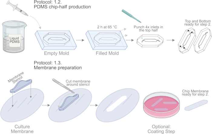
Figure 1. Graphics of PDMS chip-half production and membrane preparation. For PDMS chip-half production (step 1.2), chip molds are filled with liquid PDMS with a wide nozzle syringe, 4.4 mL in the top mold and 2.4 mL in the bottom mold. PDMS halves are cured for 2h at 65 °C, after which 4 inlets in the top chip-half are punched at the ends of the chamber and points indicated in the mold. For membrane preparation (step 1.3) printed membrane stencil is held firmly to the membrane surface. Using a new blade, one cuts around the stencil and removes the chip membrane from the surrounding material. Membranes can be coated for cell culture or used directly in step 2. Created in BioRender. Please click here to view a larger version of this figure.
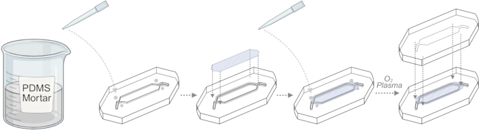
Figure 2. Membrane binding procedure. PDMS mortar is mixed as described above immediately before use. Mortar is dripped onto the four corners around the culture chamber and spread gently around the membrane binding location with the angled end of a pipette. One end of the membrane is placed on the mortar, then, once aligned with the culture chamber, gently allowed to fall into place. Mortar is reapplied drip-wise and painted over the edges of the membrane with great care taken not to allow any silicone to touch the membrane surface inside the culture area. Chip-half bound membranes are immediately put in a vacuum chamber to remove microbubbles, ensure silicone invasion into the surface and pores, and remove toluene to minimize chemical attack on the membrane. Created in BioRender. Please click here to view a larger version of this figure.
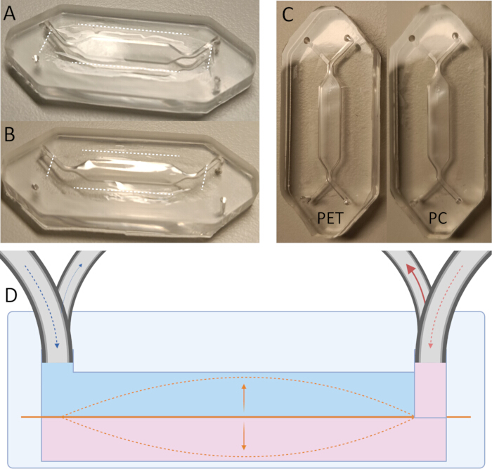
Figure 3. Membrane placement examples. (A) Successful membrane placement, curing at RT. (B) Membrane binding cured in an oven (65 °C instead of at RT, the membrane can be seen to have distended into the chamber as the silicone contracted after heating. (C) Complete chips with correct PET and PC membrane placement. (D) Incorrect membrane placement will cause the volume of each side of the chip to change with membrane movement, causing variable flow, applying stress to the cells within the chip as well as the pumps attached to the chip. Created in BioRender. Please click here to view a larger version of this figure.
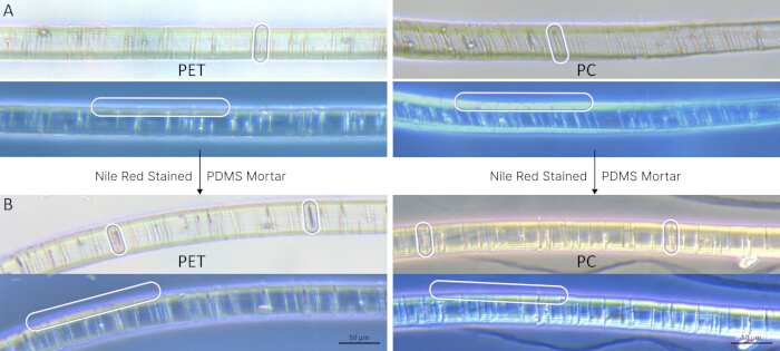
Figure 4. Light microscope images of sliced and mounted PET and PC membranes. Showing silicone invasion into membrane pores as a result of our vacuum RT curing procedure. (A) Images of the same membrane with no PDMS applied to the membrane, clear pores can be seen, as well as a clean surface in the polarized image. (B) PDMS Mortar has been stained with Nile Red, and silicone can be seen in magenta to have successfully invaded the pores and thinly coated the surface under vacuum. Highlighted in white/magenta shapes. Please click here to view a larger version of this figure.
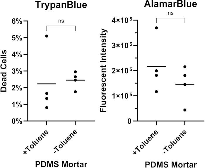
Figure 5. Cell viability in the chip devices was not altered by construction with or without toluene as a thinning agent in the PDMS mortar. Calu-3 cells were seeded at 6.5 × 10⁴ cells per chip and, upon reaching confluency, were incubated overnight before an AlamarBlue assay was performed on the supernatant and TrypanBlue on the cells. Differences between groups (n=4) prepared with and without toluene were tested by unpaired Student's t test, p > 0.05 = ns (not significant)8. Please click here to view a larger version of this figure.
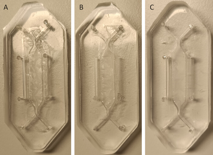
Figure 6. Basement membrane chips. (A) Membrane integrity has failed as the PDMS/toluene mortar was not vacuumed off fast enough; this has damaged the matrix proteins and disrupted chip sealing. (B) Membrane and chip sealing have succeeded, but the membrane has been sealed in a loose state. (C) Successful membrane and chip sealing, the chip is functional for flow and stretch. Please click here to view a larger version of this figure.
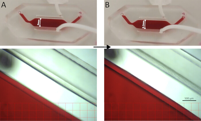
Figure 7. Two images of the ECM chip under stretch. (A) Chip at rest. (B) Chip under 1.2 mm horizontal stretch. Please click here to view a larger version of this figure.
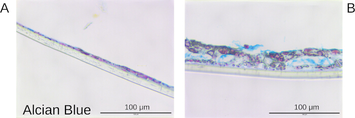
Figure 8. Alcian Blue (Nuclei in magenta, mucous in blue) staining of human lung Calu-3 epithelial cells grown in the chips after air exposure in the device. Calu-3 cells were grown to confluency and cultured for 10 days under a continuous flow rate of 150 µL/h in the basal compartment and either medium- or air-exposed from the apical side. Flow was produced with a peristaltic pump within an incubator at 37 °C and 5% CO2. At the end of culturing, the membranes were removed and stained. Transverse view of Alcian Blue staining of Calu-3 cells grown for 10 days submerged (A) and air-exposed (B)8. Please click here to view a larger version of this figure.
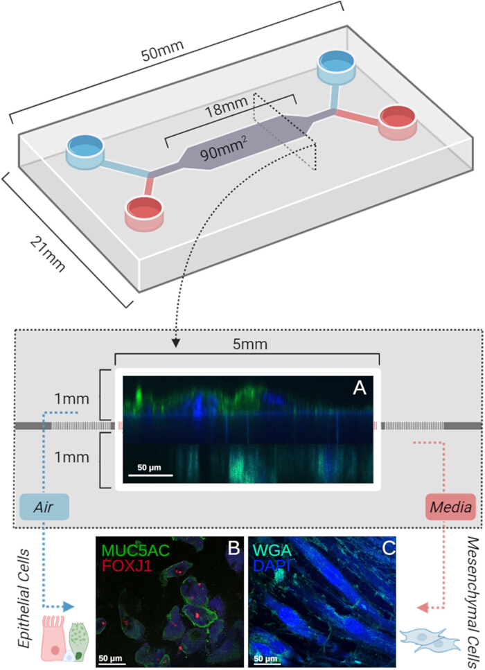
Figure 9. Visualization of primary human epithelial cells and fibroblasts in extended co-culture within the device. Airway fibroblasts were seeded into the device and allowed to attach overnight before inverting the device and seeding epithelial cells on the other side of the membrane. The cells were grown to confluency, air-exposed, and cultured for 21 days under a continuous flow rate of 150 µL/h produced with a peristaltic pump within an incubator at 37 °C and 5% CO2. The membranes were removed post-culture, fixed, embedded, and mounted on slides before staining. Epithelial cells were stained for Mucin 5AC (MUC5AC)18, a component of mucus, and forkhead box protein J1 (FOXJ1)19, a transcription factor involved in signaling for cilia production. Fibroblasts were stained with wheat germ agglutinin (WGA) to visualize the cellular phospholipid bilayers. Cells were incubated with 5 µg/mL in HBSS for 15 minutes and washed three times with PBS before imaging. All cell nuclei were visualized with DAPI. (A) Cross-section view: produced from a Z-stack projection of images of (B) and (C). (B) Epithelial MUC5AC/FOXJ1/DAPI stain on a chip membrane. (C) Complete external structure of the fibroblast layer in the basal chamber8. Please click here to view a larger version of this figure.
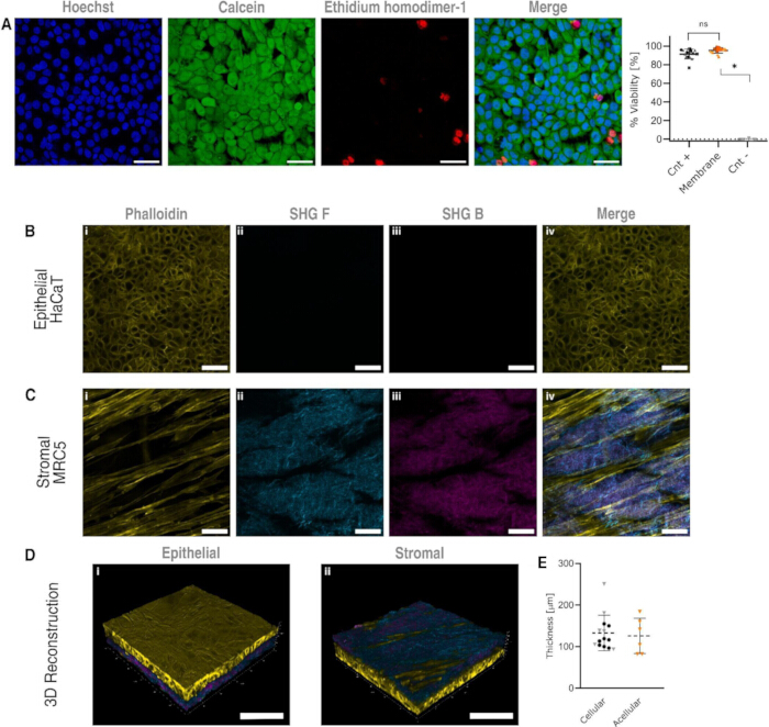
Figure 10. Cell viability and coculture on the basement membrane scaffold. (A) LIVE/DEAD viability of HaCaT cells seeded on the epithelial side, 3 independent samples were tested, 3 random fields were captured from each sample (n = 3). Ordinary one way ANOVA test with Tukey's correction was performed. The graph shows the mean with the standard deviation. Coculture of (B) HaCaT cells on the epithelial side and (C) MRC-5 lung fibroblasts on the stromal side of the basement membrane-containing scaffold surrounded by collagen fibers, scale bars are 50 µm. (D) 3D view of the coculture from top and bottom isometric views, scale bars are 100 µm, animated visualization can be found in Supplementary Figure 4. (E) Thickness of basement membrane scaffold before and after decellularization, 14 mucosas were measured, and from those, 6 (represented by triangles) were taken for decellularization. On each of the samples, three random fields were scanned and at least 10 points per field were measure17. Please click here to view a larger version of this figure.
Supplementary Figure 1. Chip mold designs for the top and bottom halves of the standard PET/PC chip. (A) Image of the bottom mold of the chip that can be produced from the .STL in Supplementary File 1. (B) Image of the top mold of the chip that can be produced from the .STL in Supplementary File 2. (C) Image of the membrane stencil for cutting membranes for the chip that can be produced from the .STL in Supplementary File 3. Please click here to download this File.
Supplementary Figure 2. Chip mold designs for the top and bottom halves of the stretch ECM membrane chip. (A) Image of the bottom mold of the chip that can be produced from the .STL in Supplementary File 4. (B) Image of the top mold of the chip that can be produced from the .STL in Supplementary File 5. Please click here to download this File.
Supplementary Figure 3. Validation of sealing procedure: comparison of PDMS intrusion into pores without toluene to lower the mortar's viscosity and cured at RT without vacuum. All conditions are with PET membranes (0.4 µm pores), after PDMS (Nile Red 1%) treatment, membranes were embedded in paraffin before mounting and light microscope imaging. (A) Unthinned PDMS vacuumed onto a PET membrane. A thick layer of PDMS can be seen on the surface of the membrane, while no PDMS can be observed to have entered the pores (highlighted with white boxes). (B) Thinned PDMS mortar vacuumed onto a PET membrane. A layer of PDMS can be seen on the surface of the membrane, while no PDMS can be observed to have entered the pores (highlighted with white boxes). (C) Thinned PDMS mortar vacuumed onto a PET membrane. A thin layer of PDMS can be seen on the surface of the membrane as well as intrusion into the pores along the membrane (highlighted with white boxes). Please click here to download this File.
Supplementary Figure 4. 3D visualization of Co-culture HaCat (epithelial) and MRC-5 (stromal) cells on the porcine ECM scaffold. An animated 3D view of the coculture from top and bottom isometric views, images of which can be seen in Figure 10D, scale bars are 100 µm. Please click here to download this File.
Supplementary File 1. 3D .STL file of the bottom mold. The mold can be used to produce the bottom half of the standard chip by 3D printing or an equivalent fabrication method. Please click here to download this File.
Supplementary File 2. 3D .STL file of the top mold. The mold can be used to produce the top half of the standard chip by 3D printing or an equivalent fabrication method. Please click here to download this File.
Supplementary File 3. 3D .STL file of the membrane stencil. The stencil can be used to produce membranes of the correct size for the provided chip and can be produced by 3D printing or an equivalent fabrication method. Please click here to download this File.
Supplementary File 4. 3D .STL file of the bottom mold of the stretch chip. The mold can be used to produce the bottom half of the stretch chip by 3D printing or an equivalent fabrication method. Please click here to download this File.
Supplementary File 5. 3D .STL file of the top mold of the stretch chip. The mold can be used to produce the top half of the stretch chip by 3D printing or an equivalent fabrication method. Please click here to download this File.
Discussion
The chip sealing protocol we provide here represents a new way to produce water-tight PDMS-membrane chip seals that are viable for long-term culture under flow, can be produced with limited equipment, and requires no specialized skills to approach. We show the procedure for producing chip wafers with membranes (PET, PC, ECM) bound to the surface with silicone mortar, and show that rapid application of vacuum facilitates intrusion of the PDMS into the pores and across the surface of plastic membranes. We also show that the resultant chips are well sealed and capable of a wide range of culture applications.
There are several different ways to approach PDMS-plastic bonding, a common bonding strategy due to the beneficial properties for cell culture of PDMS, such as gas permeability or patternability, and plastic membranes for their cell culture viability7. These include surface activation with O2 plasma, Corona, or Ozone treatment, which facilitates the formation of covalent bonds between silicone or glass20. Otherwise, chemical gluing techniques using organosilanes such as APTES ((3-Aminopropyl)triethoxysilane) or MPTMS ((3-mercaptopropyl)trimethoxysilane) to functionalize the surface of the two materials by adding reactive groups21. Alternatively, PDMS and plastic substrates can be glued with an adhesive method involving epoxy or other adhesives22. We present a hybrid between surface activation and chemical gluing, with the use of porous membranes and vacuum to produce a physical connection through the membrane that can be bonded through O2 plasma surface activation alone. By thinning the PDMS with toluene, we allow for the invasion of the PDMS through the pores of a membrane under vacuum, which allows for different membranes to be covalently bound through PDMS-PDMS bonds across the chip halves and the mortar-embedded membrane. By producing a physical silicone network through these pores, we sidestep the need for surface chemical treatment or heat and pressure provided by a hot embossing machine, which often aids these techniques23.
In the current study, a large-scale two-chambered chip is provided (Supplemental File 1) that can have a range of functions. Secondly, a chip that is capable of cyclical horizontal stretch (Supplemental File 2). These devices function as an Airway-on-Chip, while the model can also be used as a gut-on-chip, as previously shown13. Primarily, a step-by-step guide is provided with a number of different options for mold production, membrane preparation, and chip construction that could be applied to additional novel chip platforms according to the desired application of the researchers. It is recommended to use an O2 plasma oven for the final sealing. Nevertheless, a handheld plasma device or manual compression with PDMS mortar has also been seen to be successful for this step24. In this protocol for this sealing procedure, key hurdles and specifications have been highlighted at each point. These include the option to pre-coat the membranes, the importance of immediate use of the PDMS/toluene mortar, the importance that the mortar does not enter the culture area, and how essential it is that the membrane not move after connection with the mortar has been made.
Reproduction of this sealing procedure has been repeatedly performed by investigators with a written protocol; only the following clarifications have been necessary for successful sealing on a second attempt. Upon the occurrence of leakages during stress testing or extended cell culture, a few options can be explored. First, the researcher should ensure the mortar is made freshly from PDMS liquid that has not begun to cure and is thoroughly mixed with toluene. The low viscosity of the mortar is what permits a thin, smooth layer that can flow into the membrane pores as air is vacuumed out. Secondly, one should apply enough mortar to cover the entirety of the bottom and top of the membrane, while too much will cause it to flow into the culture area under compression, too little will leave gaps that provide a route for inter-chamber leakage. Thirdly, membranes must be flat before and during attachment. Finally, despite the manual effort involved, the chips must remain largely dirt-free to ensure total final bonding, thus working fast and clean is essential.
While we showed the attachment of three different types of porous membranes in this paper, the function of this method for other membranes cannot be predicted. This is because different chemical resistances to toluene, as well as other densities and sizes of pores, will affect the outcome of this sealing procedure. However, we do show the first stretchable fully ECM-based membrane binding, which suggests high versatility of the protocol. Yet, the consistency of the stretch performance has not been reliably checked, as different basement membrane regions, organs, and sources will produce mechanical differences. Additionally, the viability for cell culture of the ECM membranes is also prone to change over time, both in culture and in storage19. While this procedure works for different membranes and chip setups, it calls for manual painting of the mortar to be effective, which requires relatively little time but will be successful more often with larger-scale models such as the ones we provide. Finally, while the membrane binding process requires only PDMS, toluene, a membrane, and a vacuum chamber, the final sealing of the chip is reliant on the application of O2 plasma, which is not universally available.
Despite the limitations, the protocol provided is novel and requires no specialized skill to approach. To the best of our knowledge, the production of silicone networks through the membrane pores by vacuuming of the low-viscosity PDMS mortar is the first of its kind. Unlike other chemical or mechanical functional bridging between the different materials underlying a functional chip, this solution is possible in most lab environments.
Disclosures
The authors have no conflict of interest.
Acknowledgements
This work was supported by the Precision Medicine for More Oxygen (P4O2) consortium as well as funding from Stichting Proefdiervrij. My deepest gratitude to Isadora Kraguljac for the idea of using Nile Red stain, as it would mix with the PDMS for visualization of the silicone networks, and to Marjan Reinders-Luinge for her talented slicing and mounting of the membranes. The authors express their deepest thanks to the Pharmaceutical Analysis department and Sabeth Verpoorte for providing access to their Oxygen Plasma Oven, the process wouldn't have been possible without it.
Materials
| Name | Company | Catalog Number | Comments |
|---|---|---|---|
| 2mL wide-nozzel syringe | BD Emereld | 307727 | |
| 2mm Biopsy Punch | KAI medical | BP-20F | |
| Calu-3 Cell line | ATCC | HTB-55 | RRID: CVCL_0609 |
| HBSS (Hanks Balanced Salt Solution) | Gibco | 14170112 | |
| O2 Plasma Oven | Harrick Plasma | PDC-002 | |
| PC Track Etched Cell Culture Membranes | ipCELLCULTURE | 1000M25/620N403/47 | |
| PET Track Etched Cell Culture Membranes | ipCELLCULTURE | 2000M23/610N403/47 | |
| Polydimethylsiloxane/Sylgard 184 Silicone Elastomer base and curing agent | Dow Corning | DOWC25100445 | |
| Polymethyl methacrylate (8mm) | Colltec | N/A | |
| Standard Photopolymer Resin (Grey)(1kg) | Elegoo | N/A | |
| Toluene | Merck | 1,08,325 | |
| Vacuum Chamber | FisherScientific | 12080253 |
References
- Ugodnikov, A., Persson, H., Simmons, C. A. Bridging barriers: advances and challenges in modeling biological barriers and measuring barrier integrity in organ-on-chip systems. Lab Chip. 24 (13), 3199-3225 (2024).
- Singer, M., Akhtar, A. With What Should We Replace Nonhuman Animals in Biomedical Research Protocols. AMA J Ethics. 26 (9), E701-E708 (2024).
- Reardon, S. Beyond lab animals. Science. 389 (6761), 676-679 (2025).
- Qiu, J., Li, J., Guo, Z., Zhang, Y., Nie, B., Qi, G., et al. 3D Printing of Individualized Microfluidic Chips with DLP-Based Printer. Materials (Basel). 16 (21), 6984(2023).
- Survey on reliability of microfluidics-based devices and components. , The Microfluidics Association. https://microfluidics-association.org (2025).
- Silverio, V., Guha, S., Keiser, A., Natu, R., Reyes, D. R., van Heeren, H., et al. Overcoming technological barriers in microfluidics: Leakage testing. Front Bioeng Biotechnol. , (2022).
- Nahak, B. K., Mishra, A., Preetam, S., Tiwari, A. Advances in organ-on-a-chip materials and devices. ACS applied bio materials. 5 (8), 3576-3607 (2008).
- Rae, B., Vasse, G. F., Mosayebi, J., van den Berge, M., Pouwels, S. D., Heijink, I. H. Development of a Widely Accessible, Advanced Large-Scale Microfluidic Airway-on-Chip. Bioengineering (Basel). 12 (2), 182(2025).
- Nizamoglu, M., Joglekar, M. M., Almeida, C. R., Larsson Callerfelt, A. K., Dupin, I., et al. Innovative three-dimensional models for understanding mechanisms underlying lung diseases: powerful tools for translational research. Eur Respir Rev. 32 (169), 230042(2023).
- Piergiovanni, M., Leite, S. B., Corvi, R., Whelan, M. Standardisation needs for organ on chip devices. Lab Chip. 21 (15), 2857-2868 (2021).
- Silverio, V., Guha, S., Keiser, A., Natu, R., Reyes, D. R., van Heeren, H., et al. Overcoming technological barriers in microfluidics: Leakage testing. Front Bioeng Biotechnol. 10, 958582(2022).
- Cameron, T. C., Randhawa, A., Grist, S. M., Bennet, T., Hua, J., Alde, L. G., et al. PDMS Organ-On-Chip Design and Fabrication: Strategies for Improving Fluidic Integration and Chip Robustness of Rapidly Prototyped Microfluidic In Vitro Models. Micromachines (Basel). 13 (10), 1573(2022).
- Rae, B., Bood, V., Dijk, H. J., Vasse, G. F., Melgert, B. N., Nagelkerke, A., et al. Interorgan Communication Between Lung and Colorectal Epithelial Cells Studied Using a Novel Multi-Organ-On-Chip System. Compr Physiol. 15 (5), e70051(2025).
- van der Helm, M. W., Odijk, M., Frimat, J. P., van der Meer, A. D., Eijkel, J. C. T., van den Berg, A., et al. Fabrication and Validation of an Organ-on-chip System with Integrated Electrodes to Directly Quantify Transendothelial Electrical Resistance. J Vis Exp. (127), e56334(2017).
- Salimbeigi, G., Vrana, N. E., Ghaemmaghami, A. M., Huri, P. Y., McGuinness, G. B. Basement membrane properties and their recapitulation in organ-on-chip applications. Mater Today Bio. , (2022).
- Nawroth, J. C., et al. Breathing on chip: Dynamic flow and stretch accelerate mucociliary maturation of airway epithelium in vitro. Materials Today Bio. 21, 100713(2023).
- Ramirez, J. A., Estrada, S., Harmsen, M. C., Sharma, P. K. Development of an in vitro platform for epithelial-stromal interactions: A basement membrane-containing scaffold from decellularized porcine bladders. Matrix Biol Plus. 26, (2025).
- Bonser, L. R., Erle, D. J. Airway mucus and asthma: the role of MUC5AC and MUC5B. Journal of clinical medicine. 6 (12), 112(2017).
- Yu, X., et al. Foxj1 transcription factors are master regulators of the motile ciliogenic program. Nature genetics. 40 (12), 1445-1453 (2008).
- Lu, C. Surface modification of polyimide fibers for high-performance composite by using oxygen plasma and silane coupling agent treatment. Textile Research Journal. 92 (23-24), 4899-4911 (2022).
- Shakeri, A., Khan, S., Didar, T. F. Conventional and emerging strategies for the fabrication and functionalization of PDMS-based microfluidic devices. Lab on a Chip. 21 (16), 3053-3075 (2021).
- Borók, A., Kristóf, L., Attila, B. PDMS bonding technologies for microfluidic applications: A review. Biosensors. 11 (8), 292(2021).
- Tang, L., Nae, Y. L. A facile route for irreversible bonding of plastic-PDMS hybrid microdevices at room temperature. Lab on a Chip. 10, 1274-1280 (2010).
- Young, A. T., et al. Simple design for membrane-free microphysiological systems to model the blood-tissue barriers. Organs-on-a-Chip. 5, 100032(2023).
Reprints and Permissions
