This protocol presents the setup and operation of a patented bioreactor for mechano-immunomodulation studies. Here, using a custom bioreactor that reproduces physiological forces, we demonstrate that macrophages mount a distinctly proinflammatory response to mechanical stimulation.
A subscription to JoVE is required to view this content. Sign in or start your free trial.
Method Article
Peristalsis-Induced Mechanical Activation of Macrophages
In This Article
Summary
Abstract
Inflammation is a complex process that drives both acute and chronic diseases. It is modulated by cascading biochemical and biophysical cues that result in immune cell activation. Macrophages are a primary immune cell type that are involved in multiple inflammatory conditions, including cancer, fibrosis, and autoimmune diseases. Traditional methods of investigating macrophage activation involve biochemical stimulation with defined cytokine or chemokine cues, activating macrophages into the edges of a pro- or anti-inflammatory state. Emerging evidence suggests that biophysical cues also play a role in macrophage activation, in addition to the biochemical cues within tissues. One such prevalent mechanical cue is peristalsis, consisting of multiaxial strain and shear stress, occurring in the gastrointestinal tract, uterus, developing airways, and ureters. Here, we tested the hypothesis that peristalsis may activate macrophages. In this protocol, the use of a peristaltic bioreactor is described to investigate the mechanical activation of macrophages. Polydimethyl siloxane membranes were coated with fibronectin to enhance macrophage adhesion. Immortalized murine bone marrow derived macrophages (iBMDM) were seeded onto fibronectin-coated membranes and maintained as static controls or exposed to peristalsis for 4 h. Peristalsis activated the macrophages, with significant differences in the gene expression of Il6 (50.9 fold over static controls; p < 0.0001, t-test) and Nos2 (19.8 fold over static controls; p = 0.0046). Interestingly, no significant changes were observed in Chil3 (1.22 fold over static controls; p = 0.9726) or Mrc1 (1.16 fold over static controls; p = 0.9810) compared to static controls, indicating that mechanics primarily drove proinflammatory activation. The current findings support the concept of mechano-immunomodulation of macrophages, especially in response to peristalsis mechanics that are prevalent across many smooth-muscle-based tissues.
Introduction
Macrophages are innate immune cells that play essential roles in host defense, tissue remodeling, and the regulation of inflammation through phagocytosis and cytokine secretion1,2,3,4. Depending on stimuli within the in vivo microenvironment, undifferentiated macrophages (M0) can plastically polarize toward proinflammatory (M1) or anti-inflammatory/pro-regenerative (M2) phenotypes5,6. In vitro models are typically used to isolate these different stimuli, to better understand the complex mechanisms driving macrophage polarization. Classically activated M1 macrophages are typically induced in vitro by biochemical stimuli such as lipopolysaccharide (LPS) and interferon gamma (IFN-γ), resulting in increased expression of inflammatory mediators including inducible nitric oxide synthase (iNOS), interleukin-6 (IL6), and tumor necrosis factor alpha (TNF-α)7,8. Alternatively activated M2 macrophages are commonly induced through exposure to interleukin-4 (IL-4) and interleukin-13 (IL-13), promoting tissue remodeling and wound healing responses8,9. M2 macrophages are further subdivided into M2a, M2b, and M2c phenotypes based on distinct activation pathways and surface marker expression profiles10,11. While biochemical regulation of macrophage polarization has been extensively characterized in both in vivo and in vitro systems, macrophages reside within highly dynamic microenvironments that also contain substantial biophysical stimuli12. In addition to soluble cytokines and chemokines, macrophages are exposed to extracellular matrix and cell-cell interactions, substrate stiffness, fluid shear stress, hydrostatic pressure, and cyclic tissue deformation12,13,14. As mechanosensitive cells, macrophages can alter their inflammatory phenotypes in response to these physical cues, highlighting the importance of mechanobiology in immune regulation.
A growing body of literature has demonstrated that isolated mechanical stimuli in vitro can significantly influence macrophage activation states (Figure 1). Exposure to stiffer substrates increased M1 polarization and inflammatory cytokine production compared to softer substrates, which induced a pro-regenerative phenotype15,16,17,18,19,20. Similarly, fluid shear stress modulates macrophage phenotype in a magnitude-dependent manner, with low levels of interstitial fluid flow often promoting pro-regenerative activation21,22 while higher shear stresses similar to values seen in arteries may induce proinflammatory responses23,24,25,26,27,28. Cyclic stretching in vitro models designed to mimic musculoskeletal, myocardial, pulmonary, and intestinal tissue mechanics have also demonstrated increased expression of inflammatory mediators, although outcomes vary depending on the magnitude, duration, frequency, and dimensionality of the applied force29,30,31,32. Furthermore, macrophage mechanosensitivity differs across species and cell sources, emphasizing the importance of selecting appropriate experimental models for mechanobiology studies13,14.
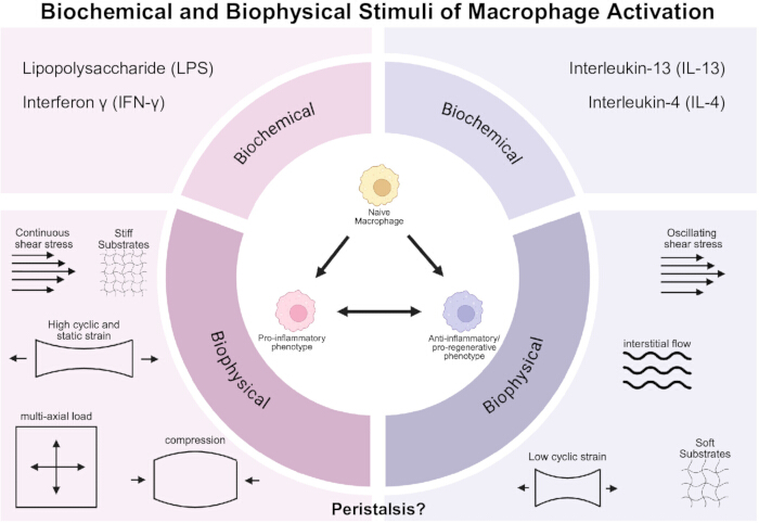
Figure 1: Schematic depicting the in vitro biochemical and biophysical stimuli of macrophage activation into either proinflammatory or pro-regenerative states. Macrophages can be stimulated into a proinflammatory state in vitro by the addition of chemical stimuli, Lipopolysaccharide (LPS), Interferon γ (IFN-γ), or exposure to mechanical stimuli, including shear stress, increased stiffness, high cyclic and static uniaxial stretch-induced strain, compression, and multiaxial compression-induced strain. Macrophages can be stimulated into a pro-regenerative state by in vitro addition of chemical stimuli, Interleukin-13 (IL-13) and IL-4. They can also become pro-regenerative when exposed to mechanical stimuli in the form of oscillating shear stress, interstitial flow, soft substrates, or low levels of uniaxial cyclic strain. Please click here to view a larger version of this figure.
In addition to investigating isolated mechanical stimuli independently, it is important to build upon this work to begin studying the impact of compounding physical forces, given that macrophages in vivo are commonly exposed to combinations of simultaneous forces. Peristalsis represents one such complex mechanical environment, consisting of concurrent multiaxial cyclic strain and fluid shear stress generated through smooth muscle contraction33. These mechanics are present across multiple organ systems, including the gastrointestinal tract, developing airways, vasculature, uterus, and ureters34,35,36. Importantly, peristaltic function is frequently dysregulated in inflammatory diseases, including fibrosis, inflammatory bowel disease, cancer, and airway remodeling disorders, all of which involve substantial macrophage-mediated inflammation33,37,38,39. Despite the recognized role of macrophages in these diseases, there remains a critical gap in understanding how peristaltic mechanical forces directly influence macrophage activation.
This protocol describes the use of a peristalsis bioreactor system to investigate macrophage mechano-immunomodulation under physiologically relevant mechanical conditions. Compared to conventional static culture systems or single-force mechanical stimulation platforms, this method enables the simultaneous application of cyclic multiaxial strain and fluid shear stress, more closely recapitulating the in vivo mechanical microenvironment of smooth muscle-based tissues. In this protocol, immortalized murine bone marrow-derived macrophages (iBMDMs) cultured in bioreactors under peristaltic conditions exhibited increased markers of M1 activation while also showing no trends towards M2 activation. These findings demonstrate that peristaltic mechanics are sufficient to modulate macrophage inflammatory behavior and support the broader concept of mechano-immunomodulation in tissues exposed to dynamic smooth muscle-driven forces. This method is particularly applicable for investigators studying mechanobiology, inflammation, tissue engineering, gastrointestinal physiology, pulmonary development, fibrosis, and other diseases in which macrophages are exposed to complex mechanical microenvironments. With careful assembly, consistent calibration, and ongoing monitoring, users can ensure reproducible bioreactor performance and avoid common limitations of this technique.
Access restricted. Please log in or start a trial to view this content.
Protocol
The protocol describes the assembly and operation of a patented40 bioreactor system for mechano-immunomodulation studies. The reagents and the equipment used are listed in the Table of Materials.
1. Cell culture
- Maintain immortalized murine bone marrow derived macrophages (iBMDMs) in complete RPMI 1640 supplemented with 10% heat-inactivated FBS, 1% HEPES buffer, 1% Sodium Pyruvate, and 1% Penicillin-Streptomycin at 37 °C supplemented with 5% CO2.
2. Polydimethylsiloxane (PDMS) fabrication
- Weigh and mix the silicone elastomer kit’s base and curing agent at a 10:1 (w/w) ratio.
- Stir the mixture for 5 min to ensure uniform blending.
- Carefully pour the mixed PDMS into a square 100 mm x 15 mm Petri dish until the PDMS reaches 3mm in height.
- Place the Petri dishes with PDMS in a desiccator.
- Degas under vacuum for 1 h to remove air bubbles.
- Remove the PDMS from the desiccator and confirm that no air bubbles remain.
- Transfer the uncured PDMS membranes to an oven preheated to 60 ˚ C, and cure for 4 h.
- Remove the PDMS membranes from the oven and allow them to cool on the benchtop overnight.
- After 18–24 h, carefully detach the cured PDMS membranes from the Petri dishes and cut to create 70 mm x 40 mm x 3 mm PDMS membranes.
3. Sterilization of the PDMS membrane
- Inside a biosafety cabinet, rinse the PDMS membranes with 70% ethanol and place them directly on the surface of the biosafety cabinet (BSC) (Supplementary Figure 1).
- Sterilize with UV for 10 min, then transfer the PDMS membrane to a non-tissue culture-treated 90 mm culture dish with the UV-exposed side facing up.
NOTE: Ensure PDMS is grabbed from the sides and never cross hands over the top of the PDMS to reduce the risk of contamination. - For peristalsis experiments, use the PDMS membranes at their original dimensions.
- For static culture conditions, cut each 70 mm x 40 mm PDMS membrane into two equal 35 mm x 40 mm halves.
4. Fibronectin coating of PDMS membranes
- Inside a BSC, prepare enough volume of sterile 0.5 mg/mL solution of fibronectin in phosphate-buffered saline (PBS) to add 100 µL per membrane.
- Dispense 100 µL of this coating solution onto the center of each PDMS membrane, ensuring that the coated region aligns precisely with the area of membrane contact between the PDMS and the screw.
NOTE: Use a pipette tip to gently spread the solution into a thin, even layer. - Leave the coated PDMS membranes in the culture dish, with the lid off, for 45 min to allow adsorption.
NOTE: Keep the BSC sash open to maintain continuous airflow. - After 45 min, aspirate the remaining fibronectin solution from each membrane.
- Rinse the membranes gently with 1 mL of sterile PBS.
5. Seeding iBMDM cells on the PDMS membrane
- At 70%–80% confluency, trypsinize the iBMDM cells cultured in a T25 flask to detach them from the surface.
- Determine cell concentration using a hemocytometer and prepare a cell density of 100,000 cells/mL in media.
- On each fibronectin-coated PDMS membrane, seed 1 mL of the prepared cell suspension per membrane.
- For each experiment, seed at least one static membrane and one peristalsis membrane to ensure parallel comparison between conditions.
- Place the seeded PDMS membranes in a humidified incubator at 37 °C with 5% CO2 for at least 24 h to allow for cell attachment for both the static and peristaltic conditions (Supplementary Figure 1B).
6. Bioreactor
- Fabricate the bioreactor using computer-aided design (CAD) files and specifications provided in the bioreactor patent (US12522795)40 or obtain a pre-assembled unit from the authors.
7. Arduino circuit assembly and calibration
- Circuit construction
- Assemble the control circuit on a breadboard using potentiometers, resistors, transistors, and conductive wiring as shown in Supplementary Figure 2.
- Install the Arduino IDE on the computer and open a new sketch.
- Set the motor speed to 5 revolutions per min (RPM) and the peristaltic pump to 28 mL/min.
- Connect the Arduino board to the computer via USB and upload the code provided in Supplementary File 1 using the Upload button in the IDE.
NOTE: The Arduino LED will turn orange during upload and return to green once ready to run. After the upload is complete, Arduino will automatically execute the program when powered.
- Motor calibration
- Start the motor and count rotations for 1 min using a stopwatch.
NOTE: Adjust the motor speed parameter in the Arduino code as needed to achieve 5 RPM. - Re‑upload the code after each adjustment until the desired speed is achieved.
- Start the motor and count rotations for 1 min using a stopwatch.
- Pump calibration
- Run the pump for 30 s and measure the collected mass to verify a flow rate of 28 mL/min (~14 g in 30 s)
- Adjust the potentiometer and repeat until the 30-s output is consistently near 14 g.
- Once both the motor and pump are calibrated, pair them with a bioreactor unit.
NOTE: The calibrated motor–pump–bioreactor assembly is now ready for experimental use (Figure 2).
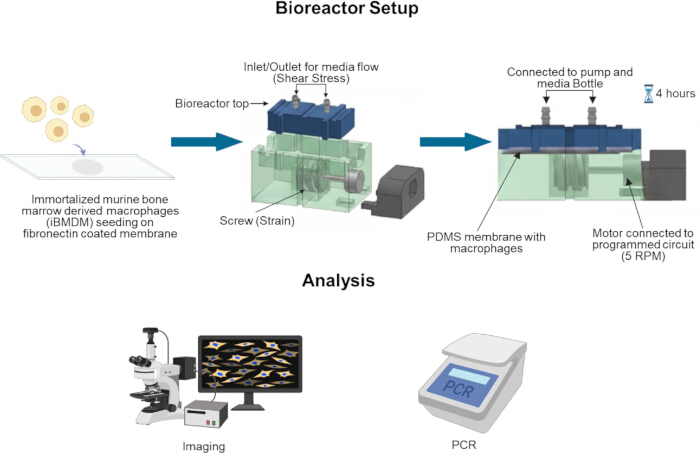
Figure 2: Schematic of peristalsis bioreactor assembly and downstream analysis. iBMDM cells are seeded on a fibronectin-coated PDMS membrane that is housed within the bioreactor. Following 4 h exposure to peristalsis or maintenance as static controls, cells are harvested for downstream analysis, including qPCR, immunofluorescent staining, and imaging. Please click here to view a larger version of this figure.
8. Assembly and setup of the peristalsis bioreactor
- Preparation of components
- Gather all required components, including media bottle, media cap, 3D printed media bottle top, 3D printed bioreactor top, 3D printed bioreactor bottom, 3D printed screw drive, zipties (three per bioreactor), slip joint pliers, diagonal pliers, 150 mm tissue culture dishes, silicone grease, and 3D-printed motor support. Spray each item with 70% ethanol before placing it inside the BSC.
- Place the DC motor, peristaltic pump, and an additional length of pump tubing inside the BSC.
- Close the BSC lid and turn on the UV for 10 min to sterilize all components (Supplementary Figure 1C).
- Verification of cell attachment and viability
- Examine both the seeded static and peristalsis PDMS membranes under the microscope. Confirm >80% cell attachment on the fibronectin-coated PDMS surfaces and inspect cell morphology for viability.
- Capture representative images of the cells prior to assembly as needed.
- Preparation of static controls
- Aspirate 1 mL of complete RPMI media from each static membrane.
- Add 1 mL of fresh complete RPMI media to each membrane.
- Label dishes as static and return them to the incubator.
- Assembly of the peristalsis bioreactor
- Add 15 mL of media to each media bottle designated for bioreactor use.
- Attach the media caps fitted with the 3D-printed bottle tops (containing inlet/outlet ports) to the media bottles. Set these aside (Supplementary Figure 1D).
- Assemble the bioreactor base.
- Insert the 3D-printed screw drive into the central well of the bioreactor bottom.
- Insert the DC motor into the motor slot on the bioreactor bottom.
- Ensure the motor driveshaft seats securely into the central hole of the 3D-printed screw drive.
- Slide the motor holder into position to stabilize the motor.
- Place the partially assembled bioreactor into a 150 mm tissue culture dish to make transfer from the BSC to the incubator easier once assembled (Supplementary Figure 1E).
- Apply a thin layer of silicone grease to the screw drive grooves where the PDMS membrane will contact the screw drive. This allows the screw to easily rotate, reducing friction.
- Loading the cell-seeded PDMS membrane
- Carefully transfer the cell-seeded peristalsis PDMS membranes from the incubator into the BSC.
- Aspirate media from each membrane and place the membrane into the bioreactor with the cell-seeded surface facing upward, opposite the greased screw-drive interface.
- Position the bioreactor top so that the cell chamber indentation aligns with the PDMS membrane. Slide the top into the guide grooves of the bioreactor bottom.
- Securing the bioreactor
- Secure the bioreactor top and bottom using zip ties and diagonal pliers.
- Trim excess zip-tie length with pliers.
- Fluidic connections and system setup
- Align the peristaltic pump so that its metal connector faces the same direction as the motor connector.
- Connect the pump tubing closest to the bioreactor to the inlet port nearest the motor on the bioreactor top. Push the tubing fully over the inlet nozzle.
- Submerge the opposite end of this tubing inside the media bottle.
- Using the additional piece of pump tubing, attach one end to the outlet nozzle of the bioreactor top, and place the other end inside the media bottle above the media level to allow recirculation without backflow (Supplementary Figure 1F).
- Incubation and operation
- Place the entire bioreactor assembly (within the 150 mm dish) inside the incubator (Supplementary Figure 1G) and keep the circuit board/Arduino outside, connected to power.
- Connect the alligator clips
- Pump: positive to positive, negative to negative.
- Motor: reverse polarity according to the circuit design.
- Place empty sterile Petri dishes in the incubator for later sample collection.
- Allow the peristalsis bioreactor system to run for 4 h (or desired length of time) (Supplementary Figure 1H) under standard culture conditions in the incubator.
9. Take down of the bioreactor
- Open the incubator and lift the inlet tubing from the media bottle to allow air to enter the system and to fully drain residual media from the bioreactor.
- Once media flow has ceased, detach the motor and/or pump leads from the circuit board to stop mechanical motion.
- Move the entire bioreactor assembly into the BSC, remove the tubing, cut the zip ties, and lift off the bioreactor top.
- Aspirate residual media from the PDMS membrane and transfer the membrane back into the same Petri dish used during preparation.
- Check for cell attachment and viability by assessing cell morphometry under a cell culture microscope, then proceed with downstream analyses as required.
10. Downstream analysis
- qPCR sample collection
- Inside the BSC, label 1.5 mL microcentrifuge tubes with sample identifiers, including cell type and experimental condition.
- Verify that cells are still present on PDMS using a cell culture microscope for both static and peristalsis conditions.
- Aspirate residual media from each PDMS membrane.
- Freshly prepare RNA lysis buffer by adding β‑mercaptoethanol Buffer RLT at a 1:100 ratio.
- Add 370 µL of Buffer RLT + β-mercaptoethanol to each PDMS membrane to lyse cells.
- Using a sterile cell scraper, firmly scrape the cell‑seeded region of the PDMS to detach all cells.
- Transfer ~350 µL of the lysate into the respective 1.5 mL tube.
- Proceed with RNA extraction or store samples at -80 °C until further use.
- Decontaminate the BSC.
NOTE: Buffer RLT and β-mercaptoethanol should be handled per their respective SDS and disposed of in the appropriate waste containers.
- Immunofluorescent staining
- Add 1 mL of 4% paraformaldehyde (PFA) to each membrane and incubate at room temperature for 20 min.
- Aspirate PFA and dispose of it in the designated hazardous waste container.
- Add 1 mL of PBS to each membrane to remove residual fixative.
- Continue with the immunofluorescent staining protocol appropriate to the target markers.
11. Cleaning of bioreactors and associated components
- Spray all bioreactor components that contact media, cells, or PDMS membranes with 70% ethanol, including the inlet and outlet ports of the bioreactor.
- Aspirate any remaining media from the media bottle, then rinse the interior by spraying 70% ethanol generously and aspirating again.
- Remove all sanitized components from the BSC and store them in a designated clean area.
- For media bottles:
- Clean with 20% bleach, swirl, and discard the contents into the sink while running water.
- Scrub with 1:10 diluted vinegar and wash with soap and ultrapure water, then rinse with 70% ethanol and dry upside down.
- Clean the media caps and pump inserts with 70% ethanol.
- Cleaning of peristaltic pumps
- Set up 250 mL beakers with either (1) 70% ethanol, (2) ultrapure water, or (3) an empty waste container.
- Connect the pump with tubing in a closed flow path and power it using the Arduino-controlled circuit board.
- Run the pump in 70% ethanol for 1 min, then in ultrapure water for 1 min to flush into the empty waste beaker.
Access restricted. Please log in or start a trial to view this content.
Results
This protocol aimed to demonstrate a reproducible method for determining how peristaltic mechanical forces directly modulate macrophage activation. Prior to bioreactor experiments, iBMDMs were confirmed to appropriately polarize in response to standard biochemical stimulation conditions. Following this protocol, PDMS membranes were coated with fibronectin and seeded with iBMDMs. Cells were allowed to adhere for 24 h prior to visual inspection to confirm successful attachment, uniform distribution across the membrane surf...
Access restricted. Please log in or start a trial to view this content.
Discussion
Current understanding of how peristaltic forces influence macrophage function remains limited despite the prevalence of dysregulated peristalsis in inflammatory diseases. While individual mechanical stimuli such as shear stress and cyclic strain are known to modulate macrophage activation, the effects of concurrent multiaxial strain and fluid flow, which together comprise peristalsis, have not been extensively investigated in the context of macrophage mechanobiology. The protocol described here provides a reproducible pl...
Access restricted. Please log in or start a trial to view this content.
Disclosures
The authors have no conflicts of interest to disclose.
Acknowledgements
This work was funded by the National Science Foundation Award Number 2440798. Figure 1 and Figure 2 were created with a licensed version of BioRender.com.
Access restricted. Please log in or start a trial to view this content.
Materials
| Name | Company | Catalog Number | Comments |
|---|---|---|---|
| 0.25% Trypsin- EDTA | Fisher | 25200056 | |
| 1.5 mL microcentrifuge tubes | USA Scientific | 1615-5510 | |
| 100 mm x 15 mm Petri dishes | Fisher | 50-190-0276 | |
| 150 mm culture dishes | Fisher | FB012925 | |
| 4% paraformaldehyde | Santa Cruz | sc-281692 | |
| 90 mm culture dishes | Fisher | FB012923 | |
| Alexa Fluor 488 Anti-F4/80 antibody | Abcam | ab204266 | |
| Alexa Fluor 647 Anti-CD40 antibody | Abcam | ab275158 | |
| Arduino Uno | Amazon | B008GRTSV6 | |
| Breadboard | Amazon | ||
| Buffer RLT | Qiagen | 79216 | |
| Cell scraper | Fisher | 353087 | |
| DAPI | MilliporeSigma | 50-874-10001 | |
| Desiccator | MilliporeSigma | Z119008 | |
| Diagonal pliers | Amazon | ||
| Fetal bovine serum | Innovative Biosciences | 11-01-500 | |
| Fibronectin | MilliporeSigma | F1141-1MG | |
| HEPES buffer | Fisher (Gibco) | 15630080 | |
| iBMDM | Applied Biological Materials Inc. (abm) | T0673 | |
| Motor | Robotshop | FT-SPARK16-360 | |
| PE Anti-Ym-1 + Ym-2 antibody | Abcam | ab211621 | |
| Penicilin-Streptomycin | Fisher | 15140122 | |
| Peristaltic pump | DigiKey | 1150 | |
| Phosphate buffer saline | Fisher | 14190250 | |
| PLA filament | Amazon | B0D7ZYCVTY | |
| Potentiometer B1K 1K Ohm | Amazon | B0CZ747F6F | |
| RPMI 1640 | Fisher | 11875085 | |
| Silicone grease | Amazon | B000XBH9HI | |
| Slip joint pliers | Amazon | ||
| Sodium Pyruvate | Cytiva Hyclone | SH3023901 | |
| Sylgard 184 Silicon elastomer kit | Fisher | NC9285739 | |
| T-25 culture flask | Fisher | 229331 | |
| Transistor | DigiKey | IRF520NPBF-ND | |
| Wiring/Alligator Clips | Amazon | ||
| Zipties 18 inch | Amazon | ||
| β-mercaptoethanol | Fisher | AC125472500 |
References
- Mass E, Nimmerjahn F, Kierdorf K, Schlitzer A. Tissue-specific macrophages: how they develop and choreograph tissue biology. Nat Rev Immunol. 2023;23(9):563-579.
- Kumar V, Kumar V. Macrophages: the potent immunoregulatory innate immune cells. In: Macrophage Activation - Biology and Disease. London: IntechOpen; 2019. doi:10.5772/intechopen.88013.
- Ross EA, Devitt A, Johnson JR. Macrophages: the good, the bad, and the gluttony. Front Immunol. 2021;12:708186.
- Sreejit G, Fleetwood AJ, Murphy AJ, Nagareddy PR. Origins and diversity of macrophages in health and disease. Clin Transl Immunology. 2020;9(12):e1222.
- Locati M, et al. Diversity, mechanisms, and significance of macrophage plasticity. Annu Rev Pathol. 2020;15:123-147.
- Mosser DM, Edwards JP. Exploring the full spectrum of macrophage activation. Nat Rev Immunol. 2008;8(12):958-969.
- Boutilier AJ, Elsawa SF. Macrophage polarization states in the tumor microenvironment. Int J Mol Sci. 2021;22(13):6995.
- Orecchioni M, Ghosheh Y, Pramod AB, Ley K. Macrophage polarization: different gene signatures in M1 (LPS+) versus classically and M2 (LPS−) versus alternatively activated macrophages. Front Immunol. 2019;10:1084.
- Huang X, Li Y, Fu M, Xin HB. Polarizing macrophages in vitro. Methods Mol Biol. 2018;1784:119-126.
- Gharavi AT, et al. The role of macrophage subtypes and exosomes in immunomodulation. Cell Mol Biol Lett. 2022;27(1):83.
- Peng Y, et al. Regulatory mechanism of M1/M2 macrophage polarization in the development of autoimmune diseases. Mediators Inflamm. 2023;2023:8821610.
- Clevenger AJ, Jha A, Moore E, Raghavan SA. Manipulating immune activity of macrophages: a materials and mechanics perspective. Trends Biotechnol. 2025;43(1):33-49.
- Khanmohammadi M, Mirzaalikhan Y, Baratchi S. Immunity in motion: the role of mechanics in macrophage biology. Cell Chem Biol. 2025;32(12). doi:10.1016/j.chembiol.2025.11.004.
- Adams S, et al. Mechano-immunomodulation: mechanoresponsive changes in macrophage activity and polarization. Ann Biomed Eng. 2019;47(11):2213-2231.
- Meizlish ML, et al. Mechanosensing regulates tissue repair program in macrophages. Sci Adv. 2024;10(11):adk6906.
- Lee M, Du H, Winer DA, Clemente-Casares X, Tsai S. Mechanosensing in macrophages and dendritic cells in steady-state and disease. Front Cell Dev Biol. 2022;10:1044729.
- Chen M, et al. Substrate stiffness modulates bone marrow-derived macrophage polarization through NF-κB signaling pathway. Bioact Mater. 2020;5(4):880-890.
- Blakney AK, Swartzlander MD, Bryant SJ. The effects of substrate stiffness on the in vitro activation of macrophages and in vivo host response to poly(ethylene glycol)-based hydrogels. J Biomed Mater Res A. 2012;100A(6):1375-1386.
- Sridharan R, Cavanagh B, Cameron AR, Kelly DJ, O'Brien FJ. Material stiffness influences the polarization state, function and migration mode of macrophages. Acta Biomater. 2019;89:47-59.
- Previtera ML, Sengupta A. Substrate stiffness regulates proinflammatory mediator production through TLR4 activity in macrophages. PLoS One. 2015;10(12):e0145813.
- Song C, et al. Microfluidic three-dimensional biomimetic tumor model for studying breast cancer cell migration and invasion in the presence of interstitial flow. Chin Chem Lett. 2019;30(5):1038-1042.
- Li R, et al. Interstitial flow promotes macrophage polarization toward an M2 phenotype. Mol Biol Cell. 2018;29(16):1927-1940.
- Son H, et al. Shear stress induces monocyte/macrophage-mediated inflammation by upregulating cell-surface expression of heat shock proteins. Biomed Pharmacother. 2023;161:114566.
- Zhou H, Scatena M, Tu LN, Giachelli CM, Nigam V. Monocyte adhesion to and transmigration through endothelium following cardiopulmonary bypass shearing is mediated by IL-8 signaling. Front Cardiovasc Med. 2024;11:1454302.
- Jui E, et al. Shear stress induces a time-dependent inflammatory response in human monocyte-derived macrophages. Ann Biomed Eng. 2024;52(11):2690-2705.
- Castro-Núñez L, Dienava-Verdooold I, Herczenik E, Mertens K, Meijer AB. Shear stress is required for the endocytic uptake of the factor VIII-von Willebrand factor complex by macrophages. J Thromb Haemost. 2012;10(9):1929-1937.
- Cheng C, et al. Atherosclerotic lesion size and vulnerability are determined by patterns of fluid shear stress. Circulation. 2006;113(23):2744-2753.
- Seneviratne AN, et al. Low shear stress induces M1 macrophage polarization in murine thin-cap atherosclerotic plaques. J Mol Cell Cardiol. 2015;89(Pt B):168-172.
- Bonito V, de Kort BJ, Bouten CVC, Smits AIPM. Cyclic strain affects macrophage cytokine secretion and extracellular matrix turnover in electrospun scaffolds. Tissue Eng Part A. 2019;25(17-18):1312-1325.
- Ballotta V, Driessen-Mol A, Bouten CVC, Baaijens FPT. Strain-dependent modulation of macrophage polarization within scaffolds. Biomaterials. 2014;35(18):4919-4928.
- Dziki JL, et al. The effect of mechanical loading upon extracellular matrix bioscaffold-mediated skeletal muscle remodeling. Tissue Eng Part A. 2018;24(1-2):128-139.
- Wehner S, et al. Mechanical strain and TLR4 synergistically induce cell-specific inflammatory gene expression in intestinal smooth muscle cells and peritoneal macrophages. Am J Physiol Gastrointest Liver Physiol. 2010;299(5):G1187-G1197.
- Clevenger AJ, et al. Rapid prototypable biomimetic peristalsis bioreactor capable of concurrent shear and multiaxial strain. Cells Tissues Organs. 2023;212(1):57-72.
- Huizinga JD. Gastrointestinal peristalsis: joint action of enteric nerves, smooth muscle, and interstitial cells of Cajal. Microsc Res Tech. 1999;47(4):239-247.
- Kunz G, Leyendecker G. Uterine peristaltic activity during the menstrual cycle: characterization, regulation, function and dysfunction. Reprod Biomed Online. 2002;4(Suppl 3):5-9.
- Hosseini G, et al. A computational model of ureteral peristalsis and an investigation into ureteral reflux. Biomed Eng Lett. 2018;8(1):91-101.
- Clevenger AJ, et al. Peristalsis-associated mechanotransduction drives malignant progression of colorectal cancer. Cell Mol Bioeng. 2023;16(4):315-330.
- Leyendecker G, Kunz G, Wildt L, Beil D, Deininger H. Uterine hyperperistalsis and dysperistalsis as dysfunctions of the mechanism of rapid sperm transport in patients with endometriosis and infertility. Hum Reprod. 1996;11(7):1542-1551.
- Iwakiri K, et al. Mechanisms underlying excessive esophageal acid exposure in patients with gastroesophageal reflux disease. Esophagus. 2017;14(3):213-218.
- Raghavan S, Crawford LZ. 3D rapid prototypable tunable peristalsis bioreactor. United States patent. 2022: US12522795.
Access restricted. Please log in or start a trial to view this content.