1. Stereotaxic Injection of Mesh Electronics into Live Mouse Brain
NOTE: Mice were anesthetized by intraperitoneal injection with a mixture of 75 mg/kg ketamine and 1 mg/kg dexdomitor. The degree of anesthesia was verified with the toe pinch method prior to beginning surgery. The body temperature was maintained by placing the mouse on a 37 °C homeothermic blanket while under anesthesia. Proper sterile technique was implemented for the surgery, including but not limited to autoclaving all metal surgical instruments for 1 h prior to use, using sterilized gloves, using a hot bead sterilizer throughout the surgery, the maintenance of a sterile field around the surgical site, the disinfection of plastic instruments with 70% ethanol, and the depilated scalp skin was prepped with iodophor prior to incision. For survival surgeries, after the conclusion of the surgery, antibiotic ointment was applied around the wound, and the mouse was returned to a cage equipped with a 37 °C heating pad. Mice were not left unattended until they had regained sufficient consciousness to maintain sternal recumbency. Mice were given buprenorphine analgesia via intraperitoneal injection at a dose of 0.05 mg/kg body weight every 12 h for up to 72 h following the surgery. Mice were isolated from other animals following surgery. Mice were euthanized via either intraperitoneal injection of pentobarbital at a dose of 270 mg/kg body weight or via transcardial perfusion.
- Anesthetize the mouse and fix it in a stereotaxic frame.
- Apply ocular lubricant to the mouse's eyes to prevent dryness while under anesthesia.
- Use a dental drill and stereotaxic frame to open a craniotomy at the desired coordinates on the skull. Open a second craniotomy away from the injection site for the insertion of a stainless-steel grounding screw or wire.
- Fix a clamping substrate to the skull with dental cement. Cut an approximately 1-mm wide gap in the substrate to improve the reliability of the folding step later in the procedure.
NOTE: A flat flexible cable (FFC) cut to a "L" shape works well (Figure 4A), although many materials would work as long as they are of the correct thickness for the 32-channel zero insertion force (ZIF) connector (designed for 0.18 ± 0.05 mm thick cables).
- Mount the pipette holder with the needle containing mesh electronics onto the stereotaxic frame using a right-angle end clamp (Figure 2C and Figure 3A).
- Attach the side outlet of the pipette holder to a 5 mL syringe fastened in a syringe pump (Figure 3D) using an approximately 0.5–1 m length of capillary tubing.
NOTE: Ensure there are no bubbles in the capillary tubing before connecting it to the pipette holder. Bubbles can interrupt the flow during injection and prevent a smooth, controlled delivery of mesh electronics.
- Use the stereotaxic frame to position the tip of the needle at the desired starting location within the brain.
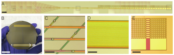
NOTE: The mesh electronics probes used here are designed with recording electrodes spread over a length of ca. 2 mm and with the first electrode located ca. 0.5 mm from the starting edge of the mesh electronics (left-most edge in Figure 1A). For this reason, the stereotaxic coordinates should be selected such that the starting location is 0.5 mm deeper than the brain region of interest. The spread and location of the recording electrodes within mesh electronics can be selected freely during the mask design process and should be selected so the recording electrodes span the brain region(s) of interest as they are injected along their stereotaxic trajectory.
- Position the camera (Figure 3B) to display the top of the mesh electronics probe within the glass needle. Some software allows the user to draw a line on the screen to mark the original position of the mesh electronics.
- Initiate the flow by setting the syringe pump to a low speed and pressing Start. 10 mL/h is a typical starting flow rate for a 400 µm inner diameter capillary needle. Slowly increase the flow rate if the mesh electronics probe does not move within the needle.
NOTE: It is important to minimize the volume of fluid injected into the brain as this can damage the tissue surrounding the injection site. Best results are achieved with injection volumes less than 25 µL per 1 mm of injected mesh length. Ideal values are less than half of this volume; in our laboratory, we typically inject 10–50 µL per a 4 mm injected mesh length.
- As the mesh electronics probe starts to move within the needle, use the stereotaxic frame to retract the needle at the same rate with which the mesh electronics probe is being injected, using the marked original position of mesh electronics as a guide.
NOTE: This procedure, termed the field of view (FoV) injection method, allows for precise delivery of mesh electronics to a targeted brain region without crumpling or dislocation. Often the flow rate can be reduced once the mesh electronics probe begins moving within the needle. In our laboratory, flow rates of 20–30 mL/h are often required to overcome the static friction between the mesh and capillary needle walls, but the rate can then be reduced to 10 mL/h once the injection process has been initiated. Flow rates and injection volumes are usually smaller for smaller diameter capillary needles.
- Continue flowing saline and retracting the needle until the needle has exited the skull. Stop the flow from the syringe pump.
2. Input/output Interfacing
NOTE: At this point, the mesh electronics probe has been injected from the desired starting point within the brain along the chosen trajectory. The needle has been retracted and is just above the craniotomy with the mesh electronics interconnects spanning from the brain to the needle and the input/output (I/O) pads still inside the needle (Figure 4B). This section uses a printed circuit board (PCB; Figure 4, Figure 5) to interface to the mesh electronics probe. The PCB connects a ZIF connector to a 32-channel standard amplifier connector through an insulating substrate that becomes the head-stage for neural recording experiments. The PCB is customizable to accommodate various head-stage configurations. Our design files are available by request or from the resource website, meshelectronics.org, and can be used to purchase PCBs inexpensively from vendors of PCB manufacture and assembly services.
- Use the stereotaxic frame to carefully guide the needle to the FFC clamping substrate and across the gap, flowing the solution with the syringe pump to generate slack in the mesh electronics interconnects (Figure 4C).
- Once the needle is above the clamping substrate and across the gap, resume the flow at a fast rate to eject the mesh electronics I/O pads onto the clamping substrate (Figure 4D).
- Using tweezers and a pipette of deionized water (DI), bend the I/O pads to ca. 90° angle as close to the first I/O pad as possible.
NOTE: The bending is necessary to allow the pads to be inserted into the ZIF connector on a PCB in a subsequent step. The ZIF connector is exactly the same width as the 32 I/O pads of the mesh electronics probe, so an imperfect 90° bend, or a bend not occurring right before the first I/O pad, will result in having to cut off I/O pads (the left-most pads in Figure 4E).
- Once the I/O pads are aligned, unfolded, and at a 90° angle to the mesh stem, dry them in place with gently flowing compressed air.
NOTE: Mesh electronics probes with fewer than 32 channels can be interfaced to with the same 32-channel interface board. For example, our lab commonly uses 16-channel mesh electronics probes with 32-channel PCBs. This provides extra space within the ZIF connector, making interfacing easier, and the additional uncontacted channels are easily identified as open circuits by means of impedance testing during recording sessions.
- Cut the clamping substrate at a straight edge approximately 0.5–1 mm from the edge of the I/O pads. Also cut off extraneous parts of the clamping substrate that will hinder the insertion into the PCB-mounted 32-channel ZIF connector (Figure 4F).
- Insert the I/O pads into the ZIF connector on the PCB and close the latch (Figure 4G). Use measurement electronics to measure the impedance between the channels and the ground screw to confirm successful interfacing. If the impedance values are too high, unlatch the ZIF connector, adjust the insertion, and retest until successful connection is confirmed.
- Cover the ZIF connector and exposed mesh electronics interconnects with dental cement for protection. Flip the PCB at the gap in the substrate, and fix the PCB with cement onto the mouse skull (Figure 4H).
NOTE: Bending the FFC at the gap reduces the mechanical strain that can sometimes break the mesh electronics interconnects.
- Allow the cement to harden, turning the PCB into a robust, compact head-stage for interfacing during subsequent recording sessions (Figure 4I).
3. Neural Recording Experiments
- Place the mouse in a tailveiner or another restrainer. Insert the preamplifier PCB into the standard amplifier connector on the head-stage PCB. Use a separate cable to ground the reference screw.
- For restrained recordings, leave the mouse in the restrainer. Record the data using the data acquisition system for the desired period (Figure 5A).
- For freely moving recordings, release the mouse from the restrainer after inserting the preamplifier PCB and grounding the reference screw. Record for the desired length of time using the data acquisition system while the mouse behaves freely (Figure 5B)