This protocol describes the workflow of robotically delivered fMRI-guided personalized transcranial magnetic stimulation therapy for treatment-resistant depression. Clinical implementation using this protocol is feasible, and open-label results support the real-world effectiveness of this approach.
Method Article
Robotically Delivered fMRI-Guided Personalized Transcranial Magnetic Stimulation Therapy for Treatment-Resistant Depression
In This Article
Summary
Abstract
Improving the outcomes of transcranial magnetic stimulation (TMS) therapy for treatment-resistant depression may be achieved by personalizing the targeting of the dorsolateral prefrontal cortex (DLPFC) and providing precise dose delivery. We recently reported the initial clinical outcomes of an open-label study using a robotically delivered functional magnetic resonance imaging (fMRI) guided, personalized TMS therapy in treatment-resistant depression. Here, we describe the protocol used in the clinical implementation of personalized TMS for treatment-resistant depression. This protocol has been clinically implemented since November 2021. Patients with treatment-resistant depression are assessed and consented for TMS therapy. Eligible patients undertake an anatomical and 15 min eyes-open, resting-state MRI. Anatomical and functional data are uploaded to a cloud-based platform to calculate the optimal TMS target within the left dorsolateral prefrontal cortex (DLPFC) via an established approach. The output of this processing pipeline identifies brain clusters characterized by the strongest anticorrelation between fMRI signals in the subgenual cingulate cortex (SGC) and DLPFC. The TMS target is refined based on individual anatomy (e.g., gyrus position) and the size of targeted cortical cluster(s). A scalp entry point for the target is calculated via neuronavigation software. Neuronavigation is used to guide a TMS coil mounted to a robotic arm, enabling precise and consistent stimulation within and across sessions. Patients undertake daily TMS sessions over 4-6 weeks using intermittent theta-burst stimulation at 120% resting motor threshold. Symptom response is assessed 2 weeks after treatment completion. This protocol demonstrates the resources and workflow required for robotically delivered fMRI-guided personalized TMS for treatment-resistant depression.
Introduction
TMS is a biological therapy indicated for treatment-resistant depression. Since the first clinical trial in 20071, there have been various iterations of TMS protocols, including the use of different coils, stimulation waveforms, number of stimulation pulses per session, number and rate of sessions per treatment, stimulation intensity, and brain targeting methods. Such therapeutic iterations contribute to the difference between the response and remission rates in early1 and more recent TMS clinical trials2,3,4,5. Another factor that may account for this difference, which is specific to brain targeting methods, is the accuracy and precision of targeting. Conventional TMS targeting relies on scalp-based heuristics, but more recent evidence suggests that treatment outcome may be related to resting-state functional connectivity (RSFC) between the dorsolateral prefrontal cortex (DLPFC) stimulation site and the subgenual cingulate cortex (SGC). This hypothesis was first proposed in 2012/136, followed by the notion that optimal connectivity-based targets might differ across individuals7. In 2021, our team developed a computational methodology that made it possible to determine reproducible connectivity-based targets with millimeter precision8. Our retrospective research in 2021 demonstrated for the first time that closer proximity to optimal connectivity-based targets was associated with better treatment outcomes9; a finding which has since been replicated10. We recently published the first prospective open-label trial demonstrating superior clinical outcomes with personalized targeting in patients with depression11, particularly those with few comorbidities. Notably, the only difference in this trial compared to conventional TMS therapy was the use of personalized connectivity-based targeting, which was delivered using a robot arm. Other TMS protocols12,13 may similarly derive part of their clinical efficacy from related targeting methodologies.
In this protocol study, we will report on the clinical, neuroimaging, and software workflows required to replicate the robotically delivered, fMRI-guided personalized TMS therapy for depression in clinical and research settings. We will comment on its real-world outcomes and implementation feasibility from our own experience of using this protocol. Lastly, we will describe how this protocol may support other therapeutic iterations, such as those aimed at adjusting dose and rate of dose delivery, or its potential advantages for treatment indications beyond depression.
Protocol
Research procedures were approved by the local Human Research Ethics Committee (Uniting Care, Brisbane, Australia), and participants provided consent. The software described in this protocol received Authorized Prescriber approval from the Therapeutic Goods Administration. Neuroimaging data processing was performed on cloud computation services (see Table of Materials) in compliance with national data privacy standards. This protocol has been in use since November 2021.
1. Pre-treatment assessment and neuroimaging
- Identify patients with metallic implants or devices, claustrophobia, and pregnancy as these clinical features present safety exclusion criteria from MRI and can affect image quality (e.g., metal artefact, movement artefact).
- Complete pre-treatment symptom severity using the Montgomery-Asberg Depression Rating Scale (MADRS),14 Hamilton Anxiety Scale (HAM-A),15 and the Hospital Anxiety Depression Scale (HADS).16 Allocate patients to sub-groups according to diagnosis of MDD without psychiatric co-morbidity (Group 1, RCT-acceptable), MDD with psychiatric co-morbidity (Group 2, Naturalistic), MDD with neurological co-morbidity (Group 3), and bipolar depression (also Group 3), similar to the prognostic classification described in Sforzini et al.17.
- Scan patients at an imaging center that has a software license for Blood-oxygen-level-dependent (BOLD) imaging. Acquire T1-weighted images, a 15 min eyes-open resting-state sequence, and two reversed phase-encoded spin-echo field maps in a 3 Tesla (3T) field strength MRI with a 64 channel coil (refer to Table of Materials).
NOTE: 3T MRI machines from any major manufacturer may be used. The full neuroimaging protocol acquisition is described in Supplementary File 1.
2. Neuroimaging preprocessing and resting-state functional connectivity analysis
- Use the dcm2niix software (refer to Table of Materials) to convert the patient’s MRI DICOM files into NIFTI format, which will also generate the BIDS-compliant JSON file and folder structures (Generation of BIDS-compliant JSON format organization is described in Li et al.18).
- Run the command-line arguments in fMRIprep (refer to Table of Materials) to commence the preprocessing workflow (fMRIprep operation is described in Esteban et al.19 and full preprocessing steps are described in Supplementary File 2).
NOTE: Pre-processing is conducted on cloud-based computation, but a high-performance cluster may also be used. - Commence the RSFC analysis by generating the SGC timeseries using the SGC seedmap, which is a template derived from 2000 scans acquired in the Human Connectome Project20. Do this by multiplying the SGC seedmap by the individual patient’s resting state fMRI data to derive the SGC timeseries (RSFC analysis steps are described in Cash et al.3).
- Compute the correlation between the time series of each voxel in the DLPFC and that of the SGC. Apply a threshold of top -0.001% to top -0.2% to the DLPFC to identify and retain only clustering voxels where the timeseries is most anticorrelated with the SGC. Compute the target site voxel in x, y, z coordinates at the center of gravity (i.e., site of maximum anti-correlation) of the largest DLPFC cluster (DLPFC targeting steps are described in Cash et al.3).
- Identify the standard space brain coordinates located at the left DLPFC’s anti-correlated cluster(s) center-of-gravity in x, y, z format. Obtain the standard space DFLPC-SGC functional connectivity map, produced in NIFTI format. Identify a standard space brain coordinate (x = -36, y = -26, z = 66) corresponding to the right abductor polices brevis motor area (M1) to approximate the target for resting motor threshold (RMT) testing.
- Warp the DLPFC and M1 coordinates and DLPFC-SGC functional connectivity map from standard space (MNI152NLin6Asym) to the patient’s native space using transforms generated by the initial preprocessing pipeline described in step 2.2. (See Supplementary File 2 for instructions on warping to native space).
- Provide the psychiatrist performing the TMS targeting the native space brain coordinates for DLPFC and M1 (in x, y, z format using RAS orientation) and the DLPFC-SGC functional connectivity map.
3. Preparation of neuronavigation
- Using the menu bar in the neuronavigation software (refer to Table of Materials), click File > New Session to navigate to the storage location of the patient’s native T1w images. Create a session folder and select either DICOM (.dcm) or nifti (.nii), depending on the storage format of the T1w images.
NOTE: Any neuronavigation software can be used, but ensure compatibility with other hardware used in the TMS workflow by referencing the user manual. - Adjust surface thresholds on the scalp and brain and pre-define anatomical landmarks on the T1w image using the following software options in the menu bar.
- Adjust scalp surface threshold to inflate or deflate using the Adjust Scalp Threshold option. Ensure minimization of epidural space or scalp overinflation from the scalp surface definition.
- Define the brain surface by segmenting brain tissues (e.g., white matter and grey matter) from non-brain tissues (e.g., dura and skull) using the brain segmentation option. Perform this by selecting A large white matter tract and clicking the Calculate button so the software can determine relative contrast values of brain and non-brain tissue. Check that the defined brain surface adequately aligns with the grey matter surface.
- Pre-define anatomical landmarks using the Patient Registration option. Mark the nasion, right tragus, and left tragus onto the patient’s native-space T1w image in preparation for coregistration with the patient’s actual scalp landmarks described in step 4.3.
- Enter the native-space DLPFC target and the M1 as x, y, z coordinates in RAS orientation using the planning option located in the menu bar.
- Reposition the DLPFC target to the nearest gyrus if it falls within a sulcus. Verify that the new brain coordinate created by the repositioning is still within the selected anti-correlated cluster by checking it in the MRI visualization software. Do this by overlaying the native space DLPFC-SGC functional connectivity map onto the patient’s native space T1w image and entering the coordinates of the repositioned brain target.
NOTE: Any MRI visualization software can be used. - Reposition the M1 coordinate to the pre-central gyrus, if necessary.
- Calculate perpendicular entry points of the TMS coil on the scalp for the DLPFC and M1 co-ordinates. Ensure the approach angle of the TMS coil, relative to the left side of the head, is programmed to be at 45° when calculating the entry point.
- Overlay a 6-by-4 entry/target grid (i.e., the M1 grid) spaced at 5-by-5 mm intervals in the entry/target option in the control area to create additional targets for resting motor threshold (RMT) testing.
4. Preparation of the robotic arm workflow
- Seat the patient in a motorized treatment chair with a neck rest. Ensure the patient is reclined with legs raised to a comfortable position and neck rest adequately supporting the head and neck.
NOTE: It is advisable to have a chair that can accommodate multiple axes of movement to achieve ideal head positioning relative to the coil placement. - Fix the patient reference tracker (a fiducial marker containing reflecting spheres) using a headband or double-sided tape to the patient’s right forehead. Position the patient’s head using the motorized chair to be in the visual field of the neuronavigation camera.
NOTE: Any neuronavigation camera may be used, but ensure compatibility with other software/hardware used in the TMS workflow by referencing the user manual. - Return to the patient registration option in the menu bar to coregister the patient’s anatomical landmarks and scalp surface to the pre-defined anatomical landmarks and scalp surface on the T1w image. Touch the pointer (a hand-held fiducial marker containing reflecting spheres) to the patient’s actual scalp landmarks, then acquire these by pressing the Green button on the foot/hand switch.
- Touch the pointer to the scalp and gently run it across the patient’s scalp to acquire three hundred scalp landmarks while pressing the green button on the foot/hand switch.
NOTE: If the patient reference tracker is moved during the session at any time after coregistration, then steps 4.3 and 4.4 must be repeated. - Check the spatial alignment accuracy of the actual and pre-defined anatomical landmarks and scalp surface at the end of the patient registration procedure, which is reported in root mean square (RMS) deviation millimeters. Ensure that RMS values are less than 3 mm; otherwise, repeat steps 4.3 and/or 4.4 until this is achieved.
- Re-position the patient in the motorized chair such that the patient reference tracker is at an ideal distance and angle for the visual field of the neuronavigation camera. Ensure that the visual field of the neuronavigation camera can also see one of the cobot (see Table of Materials) reference points (fixed fiducial markers containing reflecting spheres located on the front-left and -right side of the cobot). Check the visual field by selecting the Check Tracking System option in the menu bar.
- Enable the manual mode in the cobot option in the control area to manually move the coil-mounted robotic arm (see Table of Materials) into the workspace (indicated by the green light on the tool holder that holds the coil and the green dome visualized in the neuronavigation software). Click the Move to Park position button in the cobot option panel in the neuronavigation software’s control area to move the coil into the neutral position.
- Manually position the cobot or adjust the motorized chair positioning so the coil sits immediately above the patient’s head with a separation of several centimeters.
- Calibrate the coil’s force sensor function located in the cobot option in the control area of the neuronavigation software, which will trigger a sensor pop-up window with four pressure lights. Place a finger on the coil and gradually increase and then decrease the finger pressure on the coil such that all four pressure lights turn on and then off in a sequence.
5. Resting motor threshold testing
- Perform RMT testing at the first session of TMS. Place three electromyograph electrodes, which are connected to the MEP monitor located at the back of the TMS machine (see Table of Materials), along the ventral length of the right abductor pollicis brevis. Select the MEP protocol on the TMS machine, set the sensitivity to 200uV/div, select the Recall option, and then select the Timing option to bring up the MEP interface.
- Instruct the coil-mounted robotic arm to move to the first of the M1 targets in the grid. Do this by going to the control area, selecting the M1 target in the entry/target option panel, and then selecting the Coil Alignment button in the cobot option panel to position the coil on the patient’s scalp.
- Select the stimulator option in the control area of the neuronavigation software and set the initial stimulation intensity to 40% in the amplitude option. Click the Single Pulse button to deliver a pulse, moving in a sequential fashion to each of the targets in the M1 grid. Ensure the patient’s hand and arm are in a state of rest during RMT testing.
- Increase the stimulation intensity if required to observe an MEP (>50 mV on EMG) or thumb flexion. Observe for the strongest elicited MEP (as seen on the TMS machine screen and in the stimulation marker panel in the neuronavigation software) and largest amplitude right thumb/fingers/wrist flexion (as visually observed by the psychiatrist), indicating the optimal M1 target for RMT testing.
- Select the optimal M1 target in the Entry/Target panel and then click the Coil Alignment button in the cobot option panel to position the coil on the patient’s scalp. Increase or decrease the stimulation intensity of the single pulses at this target at set intervals until able to determine RMT. Determine the RMT by finding the minimum stimulation intensity required to evoke 5 out of 10 movements that have a minimum MEP threshold (>50 mV on EMG).
6. Delivering stimulation to the personalized DLPFC target
- Instruct the patient to close their eyes, relax, and try not to focus on any thought, as this ensures that the brain states (and optimal TMS coordinates) are similar across fMRI and TMS sessions21,22.
- Instruct the coil-mounted robotic arm to move to the DLPFC target. Do this by going to the control area, selecting the DLPFC target in the entry/target option panel, and then selecting the Coil Alignment button in the cobot option panel to position the coil on the patient’s scalp.
- Go to the menu option on the TMS machine and select the Programmed 3 minute intermittent Theta Burst Stimulation (iTBS) protocol. Select the Recall button and then the Timing button to prime the TMS machine to deliver 3 min iTBS protocol.
- Select the Stimulator option in the control area. Set the stimulation intensity at 80% RMT at the first session, 100% RMT at the second session, and 120% RMT at each session thereafter. Click the Start/Stop Trains button in the stimulator option to deliver the full train of repetitive TMS pulses.
- Perform left DLPFC stimulation daily for up to 20-30 weekday sessions (i.e., over 4-6 weeks).
7. Post-treatment assessment
- Assess the patient for treatment response up to 2 weeks after completing the last TMS session. Complete the same standardized clinician and patient-rated scales from step 1.2.
- Define treatment response as equal to or greater than 50% symptom reduction compared to pre-treatment MADRS and HAM-A scores. Define remission response as MADRS scores ≤ 10 and HAM-A scores ≤ 7 at the post-treatment assessment1.
- Review HADS scores before treatment, during TMS (at weekly intervals), and post-treatment to assess the trend in symptom response across treatment.
Results
We recently published the results of an open-label study using this protocol, as reported in Hearne et al.11. The study demonstrated an overall response rate of 52% and remission rate of 33% (N = 61; Figure 1). These findings were numerically superior to a recent open-label study (31% response rate, 23% remission rate)23, and a recent meta-analysis of clinical trial outcomes (45% response rate, 22% remission rate)24, where standard targeting methods and standardized clinician-rated scales were used. The a priori subgroups (see Step 1.2) show distinct response and remission rate profiles (Figure 1A,B), indicating that comorbidity and bipolar depression are associated with lower treatment responsiveness. Pre-treatment, the group average (N=61) functional connectivity of the SGC-DLPFC was -0.25. Using a subset of patients who undertook pre- and post-TMS fMRI (n = 28), the findings also show a specific reduction in anti-correlated RSFC (negative RSFC approaching zero) between the left DLPFC and the right SGC (Figure 2B, two-tailed paired t test: Mdiff = −0.10, t(26) = 4.34, d = 0.63, p < 0.001). Lastly, we assessed possible changes in regional brain activity using the fractional amplitude of low-frequency fluctuations (fALFF) in the SGC. The group-average fALFF in the SGC decreased from pre-treatment (0.19) to post-treatment (0.18) (t(26)=2.18, d=0.34, p=.039, uncorrected). This reduction has a weak correlation with changes in depression severity (MADRS scores).
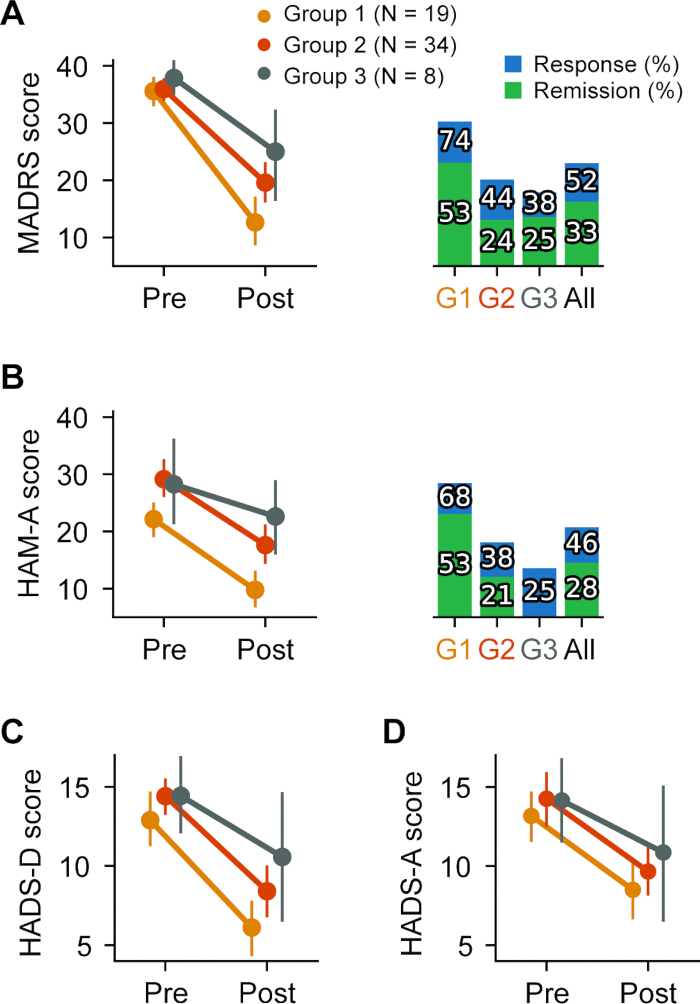
Figure 1: Personalized TMS clinical outcomes. (A) Pre-and post-treatment mean Montgomery–Åsberg Depression Rating Scale (MADRS) scores by a priori subgroup (G1: RCT-like, G2: Naturalistic, G3: Bipolar and Neurological co-morbidity), with 95% confidence intervals, are visualized on the left. The proportion of patients achieving clinical response (i.e., 50% symptom reduction) and remission (≤ 10 symptom score) for each a priori subgroup and for the total cohort (All) is visualized on the right. (B) Pre- and post-treatment mean Hamilton Anxiety Rating Scale (HAMA-A) scores by a priori subgroup, with 95% confidence intervals, are shown on the left. The proportion of patients achieving clinical response (i.e., 50% symptom reduction) and remission (≤ 7 symptom score) for each a priori subgroup and for the total cohort (All) is visualized on the right. (C) Change in Hospital Anxiety and Depression Scale - Depression (HADS-D) scores for each a priori subgroup. (D) Change in Hospital Anxiety and Depression Scale - Anxiety (HADS-A) scores for each a priori subgroup. This figure has been modified from11. Please click here to view a larger version of this figure.
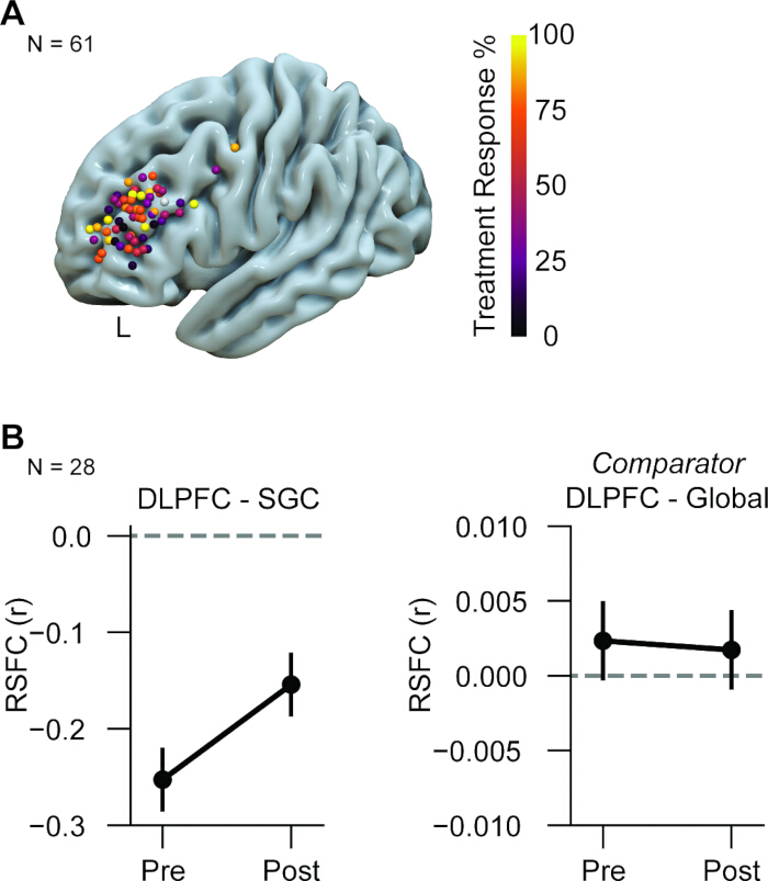
Figure 2: Personalized TMS stimulation targets for each patient and group average change in resting-state functional connectivity pre- and post-treatment. (A) Left dorsolateral prefrontal cortex (DLPFC) stimulation targets for each patient (N=61), color-coded by percentage reduction in the Montgomery–Åsberg Depression Rating Scale (MADRS) score from pre- to post-treatment. (B) Group-average change in resting-state functional connectivity (RSFC) (repeated measures 95% confidence intervals) between personalized stimulation site in DLPFC and subgenual cingulate (SGC) for a subgroup of patients who undertook post-treatment fMRI (N=28) is visualized on the left. For comparison, the group average change in RSFC between personalized stimulation in the DLPFC and across all other brain regions (Global) is visualized on the right. This figure has been modified from11. Please click here to view a larger version of this figure.
Supplementary File 1: Neuroimaging protocol. Please click here to download this file.
Supplementary File 2: Neuroimaging preprocessing, denoising, and warping from standard space to native space protocol. Please click here to download this file.
Discussion
This protocol provides a high-level summary of the fMRI-personalized targeting of TMS for patients with treatment-resistant depression using a neuronavigation and robotically delivered coil setup. The critical steps of this protocol require an understanding of various MRI, software, and neuronavigation dependencies, such that the accuracy conferred by RSFC targeting can be precisely delivered in the clinic. Firstly, this protocol necessitates access to a radiography service with a software license to acquire BOLD images. Critically, at least 15 min of resting-state BOLD acquisition with a ~2mm isotropic voxel resolution is recommended for adequate SNR when analyzing RSFC from the SGC, as described in Cash et al.8. Subsequent preparation of the fMRI data for RSFC analysis is permitted through the use of publicly available, standardized preprocessing software packages (the use of these packages for commercial purposes requires ad hoc permissions). Once the fMRI data is preprocessed, RSFC analysis includes the extraction of a weighted time series from the right SGC in a standard brain space, which is then correlated with the time series of the left DLPFC to generate a functional connectivity map. This map is then thresholded to identify anticorrelated clusters. The selection of the personalized DLPFC brain coordinate for stimulation is determined by how consistently an anti-correlated cluster is identified at various thresholds and the location of the nearest gyrus relative to the maxima of the anti-correlated cluster. Once the brain coordinate selected is warped from standard to native brain space, it is reported to the psychiatrist for TMS target planning in the neuronavigation software. The neuronavigation software is used to co-register the patient’s scalp surface and anatomical landmarks against those predefined in the MRI image, so that the targeting of the brain coordinates can be planned accurately and precisely. Use of the robotic-arm-mounted coil ensures the accuracy conferred by the RSFC targeting can be precisely delivered to the intended brain coordinate within and across sessions. It is crucial that the patient’s brain state prior to TMS delivery is like that instructed at the time of the fMRI acquisition (i.e., resting state).
In using this protocol since 2021, we have made several modifications to improve reliability and streamline the clinical implementation of the method. For example, initially, we used a BOLD acquisition method called multiband, set to a factor of 8, to prioritize temporal resolution through multi-slice acquisition (i.e., more data acquired in a given time). However, this caused SNR issues at the SGC, which were particularly amplified in patients with more head motion. Moreover, the multiband 8 caused significant image distortions. The use of the lower multiband factor (i.e., 4) limited these issues, improving the reliability of the seed-based correlation maps generated from subcortical regions25, such as the SGC. A second modification was to provide the psychiatrist with the SGC-DLPFC functional connectivity map and at least two cluster options. This allowed the psychiatrist to adapt the brain coordinate in the event of a deep or sulcal target and re-position targets that were intolerable to the patient (due to facial and trigeminal nerve stimulation), while still maintaining confidence in stimulating within a selected cluster. While this approach allows for more clinician agency over selection of the brain coordinate, other similar RSFC protocols have automated this process, such that only gyrus-based coordinates are given to the clinician26. Lastly, we initially implemented the software pipelines for preprocessing and RSFC analysis in a local high-performance cluster. We later implemented these analysis pipelines using a medically compliant cloud-based service, easing their use by non-research staff. Transitioning this workflow from a local, research-specific high-performance computational cluster to a cloud platform improved reproducibility and scalability, enabling consistent execution across clinical sites and simplifying the deployment of standardized fMRI preprocessing and connectivity analysis pipelines. This scalability supports broader clinical translation and multi-center reproducibility of personalized TMS protocols.
The main limitation of the current protocol is its resource- and expertise-intensive nature, which raises accessibility and economic considerations for the end-user (e.g., clinicians and patients)3,27. Firstly, sourcing a radiography service with the software license to perform BOLD imaging may be difficult, since the commercial and clinical use of fMRI is limited. An additional consideration of this MRI dependency is that some patients are precluded from using this protocol due to safety concerns (e.g., implanted devices, pregnancy, claustrophobia). However, in our experience, the number of TMS-eligible patients excluded from this method due to MRI safety issues is uncommon (<5%). Secondly, fees associated with MRI acquisition, software processing, and the use of neuronavigation need to be factored into the cost-benefit consideration for the patient and the business model of the TMS clinic. Future studies are required to assess the cost-effectiveness of the targeting method versus standard TMS targeting methods. This analysis will be conducted in an upcoming clinical trial (ACTRN12625000528459). The expertise required to carry out this protocol still necessitates an ecosystem of scientific and clinical staff to translate from bench to bedside. However, integrated solutions, where the software required for MRI preprocessing and RSFC analysis is incorporated into the neuronavigation and robotic TMS setup, are already on the horizon28. Such setups will incorporate pragmatic solutions to minimize or eliminate the need for the end-user to troubleshoot, such as the aforementioned method that provides automated targeting of the gyrus26. Also, future work is needed to determine whether real-time monitoring of brain activity using electroencephalography (EEG) could offer a more practical and cost-effective approach to personalize and potentially improve TMS therapy for depression29,30,31.
Evidence is emerging that the increase in accuracy and precision of RSFC-based targeting, particularly when supported by neuronavigation and robotic-arm coil delivery, confers advantages over scalp-based targeting and other coil mounting methods. Not only have we published the open-label study indicating superior outcomes relative to similar studies using standard targeting methods11, but a recent naturalistic study has also shown the improvement in treatment outcomes that is specific to the RSFC targeting, independent of the improvements conferred by an increase in TMS dose when using accelerated protocols32. This demonstrates that addressing the sources of TMS outcome variance is indeed in part related to the accuracy and precision of stimulation, independent of the variance induced by differences in dosing. On a related note, a common implementation of RSFC targeting is its use in conjunction with accelerated TMS protocols5,12,13,32,33, where increased duration, rate, and total number of treatment sessions deliver higher doses in a manner that is intensive on the patient and the TMS operator. Use of RSFC targeting in this setting requires neuronavigation, though the use of a coil-mounted robotic arm is not obligatory. Nonetheless, the robotic arm confers advantages over a fixed arm-mounted coil in terms of controlling for patient head motion34, which is more likely to occur in longer-duration TMS sessions and would be cumulative over repeated sessions. Additionally, robotic automation improves TMS operator reliability and safety and reduces fatigue compared to hand-held coil approaches27. This is particularly relevant to intensive protocols such as accelerated TMS, which have significant workforce implications (e.g., extended work hours, rotating clinical staff).
Brain circuit-based targeted neurostimulation, as described in this protocol, will more readily expand beyond the treatment indication of depression and the TMS modality. Conditions such as Obsessive Compulsive Disorder (OCD), where resting-state brain dynamics are reliably characterized by disturbances in frontostriatal systems22,35,36,37, may be the next condition amenable to functional connectivity-based targeting of non-invasive neurostimulation. Indeed, the treatment-resistant nature of OCD may be in part accounted for by the disorder’s biological heterogeneity, where functional differences arising at the individual level may require personalized approaches38. Future work is needed to assess if neuronavigated robotic targeting may be necessary for accurate and precise delivery of TMS to small cortical structures27, such as the orbitofrontal cortex, which is consistently implicated in OCD pathology36. Furthermore, subcortical regions implicated in OCD, such as the ventral striatum37, may benefit from robotic approaches deploying emerging non-invasive neurostimulation technologies, such as focal ultrasound39,40, where precision is not only necessary for effectiveness but also for safety.
Disclosures
All authors are involved in the Queensland Neurostimulation Centre. L.J.H., A.Z., R.C, and L.C. are not paid by QNC, while B.B. (psychiatrist) and V.N. (software engineer) received monetary compensation for their work with QNC. B.B. is the director of Queensland Neurostimulation Centre (QNC), where the clinical workflow took place. This is a Not-For-Profit clinic that provides transcranial magnetic stimulation services. L.C. and B.B. served as co-inventors on patent applications that cover neuroimaging-based personalized TMS. L.C. is involved in the development of imaging-based personalized TMS for depression with Resonait and ANT Neuro. The provisional patent and products from ANT Neuro and Resonait are not directly related to this work. L.C. serves on the editorial boards of Wiley Human Brain Mapping, which had no role in the study.
Acknowledgements
Thank you to I Cruice, S Thwaites, S Issa, J Miller, and J Ng, who supported the clinical workflow and collected data. This work was supported by the Australian NHMRC (2001283 and 2027597, L.C.). L.J.H. was supported by a research fellowship from the NHMRC (1194070).
Materials
| Name | Company | Catalog Number | Comments |
|---|---|---|---|
| 64 channel head and neck coil | Siemens | 10606850 | |
| Cloud computation Service | Amazon | https://aws.amazon.com/?refid=536ef9fe-bc1d-4318-ae84-3df0523ed98a | |
| Cobot | Axilum | https://www.axilumrobotics.com/en/ | This cobot has specific integration software and hardware integration with the neuronavigation system and coil. |
| dcm2niix | Rordern Lab | https://www.nitrc.org/plugins/mwiki/index.php/dcm2nii:MainPage; https://github.com/rordenlab/dcm2niix | See https://www.nitrc.org/plugins/mwiki/index.php/dcm2nii:MainPage; https://github.com/rordenlab/dcm2niix for operation manual. |
| fMRIPrep | NiPreps | https://fmriprep.org/en/stable/api.html | Open source software tool for fMRI pre-processing, see https://fmriprep.org/en/stable/ for operation manual. |
| MRI machine | Siemens | 166026 | 3 Tesla field strength. |
| MRICron | NITRC | https://www.nitrc.org/projects/mricron | Open source software tool for visualising MRI images, see https://www.nitrc.org/projects/mricron for operation manual. |
| Neuronavigation camera | Northern Digital Inc. | P7-11191 | This neuronavigation camera, and others in the range by the same manufacturer are compatible with TMS Navigator |
| TMS coil | MagVenture | 9016 E0151 | This coil is designed to hardware integrate with the cobot robotic arm and comes with its own coolant system. |
| TMS neuronavigation system | Localite | 10225 | This neuronavigation system has specific integrated software functions with the cobot and TMS stimulator. |
| TMS stimulator | MagVenture A/S | 9016E0721 | This TMS stimulator system is designed to integrate with the coil and the neuronavigation system for stimulation feedback (e.g., pulse number, motor evoked potential recording). |
References
- O’reardon, J. P., et al. Efficacy and safety of transcranial magnetic stimulation in the acute treatment of major depression: A multisite randomized controlled trial. Biol Psychiatry. 62 (11), 1208-1216 (2007).
- Luehr, J. G., Fritz, E., Turner, M., Schupp, C., Sackeim, H. A. Accelerated transcranial magnetic stimulation: A pilot study of safety and efficacy using a pragmatic protocol. Brain Stimulat Basic Translat Clin Res Neuromodulat. 17 (4), 860-863 (2024).
- Ramos, M. R. F., et al. Accelerated theta-burst stimulation for treatment-resistant depression: A randomized clinical trial. JAMA Psychiatry. 82 (5), 442-450 (2025).
- Blumberger, D. M., et al. Effectiveness of theta burst versus high-frequency repetitive transcranial magnetic stimulation in patients with depression (three-d): A randomised non-inferiority trial. Lancet. 391 (10131), 1683-1692 (2018).
- Cole, E. J., et al. Stanford neuromodulation therapy (snt): A double-blind randomized controlled trial. Am J Psychiatry. 179 (2), 132-141 (2022).
- Fox, M. D., Halko, M. A., Eldaief, M. C., Pascual-Leone, A. Measuring and manipulating brain connectivity with resting state functional connectivity magnetic resonance imaging (fcmri) and transcranial magnetic stimulation (tms). Neuroimage. 62 (4), 2232-2243 (2012).
- Fox, M. D., Liu, H., Pascual-Leone, A. Identification of reproducible individualized targets for treatment of depression with tms based on intrinsic connectivity. Neuroimage. 66, 151-160 (2013).
- Cash, R. F., Cocchi, L., Lv, J., Fitzgerald, P. B., Zalesky, A. Functional magnetic resonance imaging–guided personalization of transcranial magnetic stimulation treatment for depression. JAMA Psychiatry. 78 (3), 337-339 (2021).
- Cash, R. F., et al. Personalized connectivity-guided dlpfc-tms for depression: Advancing computational feasibility, precision and reproducibility. Human Brain Mapping. 42 (13), 4155-4172 (2021).
- Siddiqi, S. H., Weigand, A., Pascual-Leone, A., Fox, M. D. Identification of personalized transcranial magnetic stimulation targets based on subgenual cingulate connectivity: An independent replication. Biol Psychiatry. 90 (10), e55-e56 (2021).
- Hearne, L. J., et al. Clinical and neurophysiological effects of robotically-delivered fmri-guided personalized transcranial magnetic stimulation therapy for depression. Psychother Psychosomat. 94 (4), 225-331 (2025).
- Cole, E. J., et al. Stanford accelerated intelligent neuromodulation therapy for treatment-resistant depression. Am J Psychiatry. 177 (8), 716-726 (2020).
- Koh, J. Z. J., et al. Personalized transcranial magnetic stimulation treatment for depression: An open label pilot trial. Brain Stimulat Basic Translat Clin Res Neuromodulat. 18 (1), 480-481 (2025).
- Montgomery, S. A., Åsberg, M. A new depression scale designed to be sensitive to change. Br J Psychiatry. 134 (4), 382-389 (1979).
- Hamilton, M. The assessment of anxiety states by rating. Br J Med Psychol. 32 (1), 50-55 (1959).
- Zigmond, A. S., Snaith, R. P. The hospital anxiety and depression scale. Acta Psychiatrica Scandinavica. 67 (6), 361-370 (1983).
- Sforzini, L., et al. A delphi-method-based consensus guideline for definition of treatment-resistant depression for clinical trials. Mol Psychiatry. 27 (3), 1286-1299 (2022).
- Li, X., Morgan, P. S., Ashburner, J., Smith, J., Rorden, C. The first step for neuroimaging data analysis: Dicom to nifti conversion. J Neurosci Meth. 264, 47-56 (2016).
- Esteban, O., et al. Fmriprep: A robust preprocessing pipeline for functional mri. Nat Meth. 16 (1), 111-116 (2019).
- Van Essen, D. C., et al. The human connectome project: A data acquisition perspective. Neuroimage. 62 (4), 2222-2231 (2012).
- Cocchi, L., et al. Effects of transcranial magnetic stimulation of the rostromedial prefrontal cortex in obsessive–compulsive disorder: A randomized clinical trial. Na Mental Health. 1 (8), 555-563 (2023).
- Cocchi, L., et al. Transcranial magnetic stimulation in obsessive-compulsive disorder: A focus on network mechanisms and state dependence. NeuroImage Clin. 19, 661-674 (2018).
- Bouaziz, N., et al. Real world transcranial magnetic stimulation for major depression: A multisite, naturalistic, retrospective study. J Affective Disord. 326, 26-35 (2023).
- Cao, X., Deng, C., Su, X., Guo, Y. Response and remission rates following high-frequency vs. Low-frequency repetitive transcranial magnetic stimulation (rtms) over right dlpfc for treating major depressive disorder (mdd): A meta-analysis of randomized, double-blind trials. Front Psychiatry. 9, 413(2018).
- Risk, B. B., et al. Which multiband factor should you choose for your resting-state fmri study. NeuroImage. 234, 117965(2021).
- Kong, R., et al. Network-based near-scalp personalized brain stimulation targets. bioRxiv. , (2025).
- Bai, W., et al. Robot-assisted transcranial magnetic stimulation (robo-tms): A review. IEEE Transact Neural Syst Rehabilitat Eng. 33, 2606-2621 (2025).
- Yang, Z., Luo, N., Fan, L., Jiang, T. Neuromodulation robot for precision tms. Aperture Neuro. 5 (Suppl 1), (2025).
- Faller, J., et al. Daily prefrontal closed-loop repetitive transcranial magnetic stimulation (rtms) produces progressive eeg quasi-alpha phase entrainment in depressed adults. Brain Stimulat. 15 (2), 458-471 (2022).
- George, M. S., et al. Eeg synchronized left prefrontal transcranial magnetic stimulation (tms) for treatment resistant depression is feasible and produces an entrainment dependent clinical response: A randomized controlled double blind clinical trial. Brain Stimulat. 16 (6), 1753-1763 (2023).
- Pantazatos, S. P., et al. The timing of transcranial magnetic stimulation relative to the phase of prefrontal alpha EEG modulates downstream target engagement. Brain Stimulat. 16 (3), 830-839 (2023).
- Desouza, D. D., et al. Naturalistic outcomes with fmri-guided and non-fmri-guided accelerated tms for depression. medRxiv. , (2025).
- Cole, E., et al. accelerated intelligent neuromodulation therapy for treatment-resistant depression (saint-trd). Brain Stimulat Basic Translat Clin Res Neuromodulat. 12 (2), 402(2019).
- Richter, L., Matthäus, L., Schlaefer, A., Schweikard, A. Fast robotic compensation of spontaneous head motion during transcranial magnetic stimulation (tms). UKACC Int Conf CONTROL 2010. , (2010).
- Cocchi, L., et al. Functional alterations of large-scale brain networks related to cognitive control in obsessive-compulsive disorder. Human Brain Mapping. 33 (5), 1089-1106 (2012).
- Naze, S., et al. Mechanisms and interventions promoting healthy frontostriatal dynamics in obsessive-compulsive disorder. Nat Comm. 16 (1), 7400(2025).
- Webb, L., et al. Altered striatal functional gradients in obsessive-compulsive disorder. Biol Psychiatry Cognitive Neurosci Neuroimag. 10 (11), 1134-1142 (2025).
- Cocchi, L., Zalesky, A. Personalized transcranial magnetic stimulation in psychiatry. Biol Psychiatry Cognitive Neurosci Neuroimag. 3 (9), 731-741 (2018).
- De Souza, D. N., et al. Focused ultrasound as an emerging therapy for neuropsychiatric disease: Historical perspectives and a review of current clinical data. Psychiatry Clin Neurosci. 79 (5), 215-228 (2025).
- Riva-Posse, P., Figee, M. A safe step in the right direction: Focused ultrasound in obsessive-compulsive disorder and depression. Biol Psychiatry. 97 (7), 664-665 (2025).
- Gorgolewski, K., et al. Nipype: A flexible, lightweight, and extensible neuroimaging data processing framework in Python. Front Neuroinfo. 5, 13(2011).
- Wang, H. T., et al. Continuous evaluation of denoising strategies in resting-state fmri connectivity using fmriprep and nilearn. PLoS Computat Biol. 20 (3), e1011942(2024).
- Avants, B. B., Tustison, N., Song, G. Advanced normalization tools (ANTS). Insight J. 2 (365), 1-35 (2009).
Reprints and Permissions
