Edwin H. Hall, in the year 1879, devised an experiment that could be used to identify the polarity of the predominant charge carriers in a conducting material. From a historical perspective, this experiment was the first to demonstrate that the charge carriers in most metals are negative.
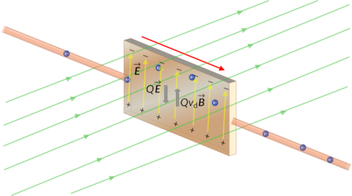
Consider a metal slab of width L in a constant magnetic field. The electrons move from the right to the left, so the magnetic force they experience pushes the electrons to the top edge of the slab. This leaves an excess negative charge at the top edge of the slab and an excess positive charge at the bottom edge of the slab, resulting in an electric field directed from the bottom to the top. The charge concentration at both edges builds until an equilibrium condition is established. At equilibrium, the electric force on the electrons in one direction is balanced by the magnetic force in the opposite direction. This scenario in which the electric and magnetic fields are perpendicular to one another is called a crossed-field situation.
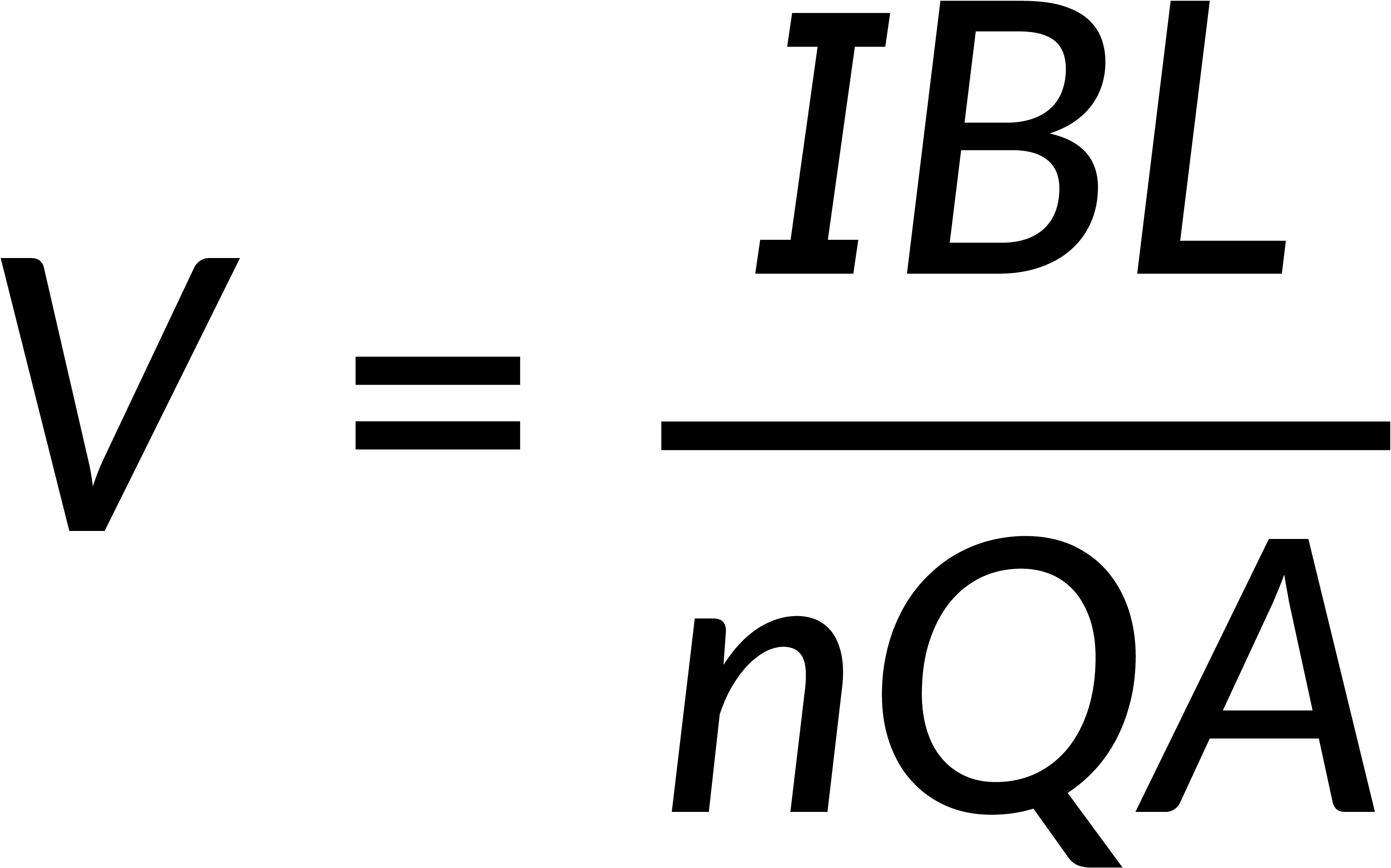
The current in the slab I can be written in terms of the drift velocity, vd, and the cross-sectional area of the slab, A. The potential difference between the edges of the strip, which is otherwise called the Hall voltage, is given by,
The polarity of the Hall voltage shows whether the charge carriers are positive or negative. Another important application of this effect is for materials with a known density of charge carriers. The measured Hall voltage can give the value of an unknown magnetic field. In research laboratories in which the fields of the electromagnets used for precise measurements have to be highly steady, a "Hall probe" is commonly used as part of the electronic circuit to regulate the field.