An ohmmeter is a resistance-measuring device. It works by applying a voltage to a resistor of unknown resistance and measuring the current across the resistor. The resistance value is deduced using Ohm's law. Usually, the standard configuration of an ohmmeter comprises a voltmeter or an ammeter. However, such configurations are limited in accuracy because the meters alter the voltage applied to the resistor and the current that flows through it.
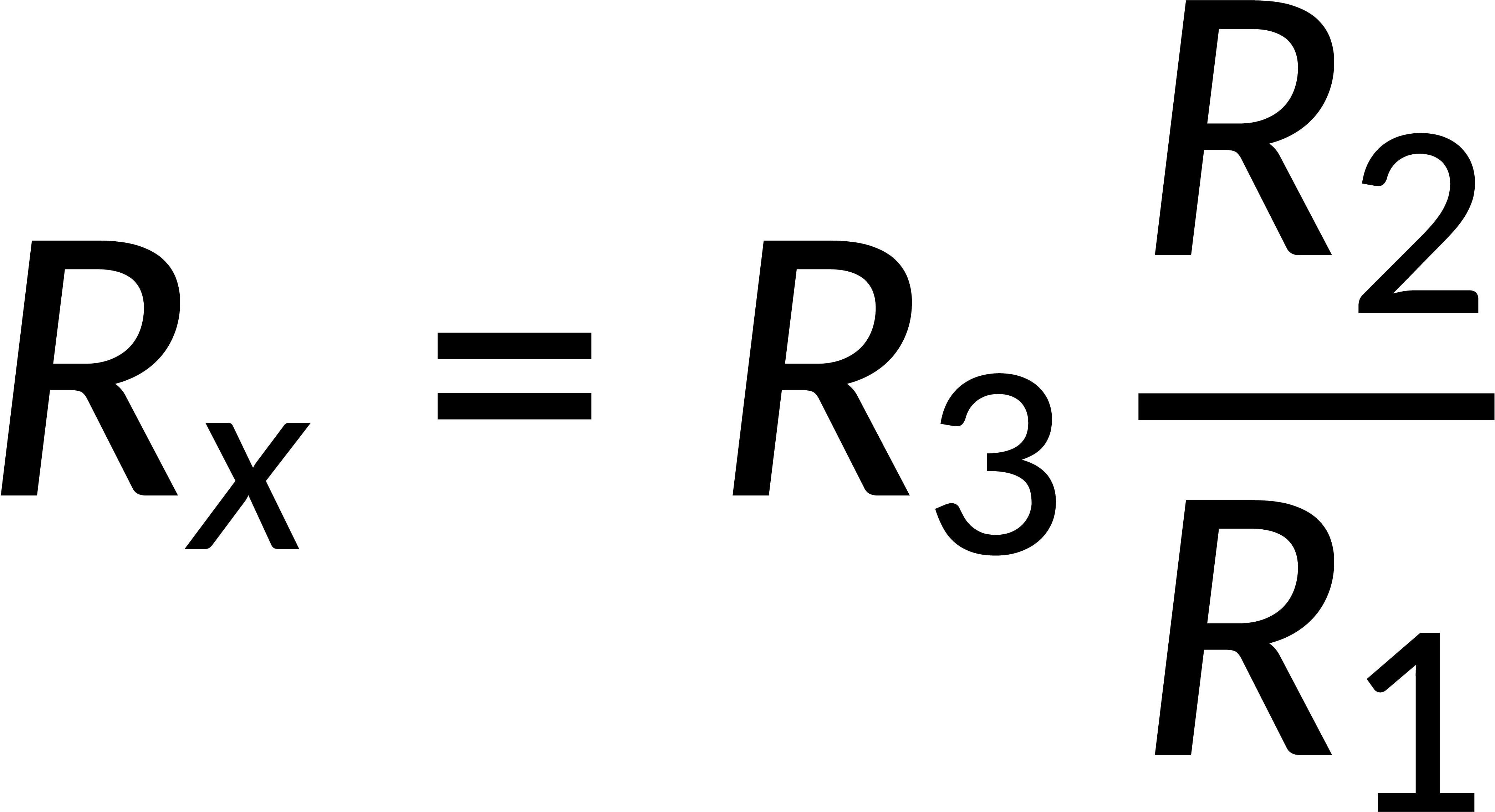
Thus, for accurate resistance measurements, a technique is required that does not draw any current from the circuit. A Wheatstone bridge is one such technique. It is a null measurement device that measures the unknown resistance by balancing the potential drops. It consists of two branches of a parallel circuit connected by a galvanometer. The galvanometer acts as a bridge between the two branches. Thus, it is called a bridge circuit. The bridge circuit is connected to a voltage source. The branches have four resistors: two have precisely known resistance, one has variable resistance, and one is an unknown resistor. The variable resistor is adjusted until the galvanometer shows zero deflection. At this point, the circuit is balanced; there is no current flow through the galvanometer branch. The following expression gives the value of unknown resistance in terms of the known resistance values in the balanced condition:
This method of measuring resistance is more accurate compared to standard voltmeters. However, two significant factors can affect the accuracy:
- Getting the current through the galvanometer to zero is impossible in real circuits.
- There is always some uncertainty in the known resistance values, contributing to the uncertainty in the unknown resistance.