Optical detection of ultrasound is impractical in many imaging scenarios because it often requires stable environmental conditions. We demonstrate an optical technique for ultrasound sensing in volatile environments with miniaturization and sensitivity levels appropriate for optoacoustic imaging in restrictive scenarios, e.g. intravascular applications.
A subscription to JoVE is required to view this content. Sign in or start your free trial.
Method Article
Wideband Optical Detector of Ultrasound for Medical Imaging Applications
In This Article
Summary
Abstract
Optical sensors of ultrasound are a promising alternative to piezoelectric techniques, as has been recently demonstrated in the field of optoacoustic imaging. In medical applications, one of the major limitations of optical sensing technology is its susceptibility to environmental conditions, e.g. changes in pressure and temperature, which may saturate the detection. Additionally, the clinical environment often imposes stringent limits on the size and robustness of the sensor. In this work, the combination of pulse interferometry and fiber-based optical sensing is demonstrated for ultrasound detection. Pulse interferometry enables robust performance of the readout system in the presence of rapid variations in the environmental conditions, whereas the use of all-fiber technology leads to a mechanically flexible sensing element compatible with highly demanding medical applications such as intravascular imaging. In order to achieve a short sensor length, a pi-phase-shifted fiber Bragg grating is used, which acts as a resonator trapping light over an effective length of 350 µm. To enable high bandwidth, the sensor is used for sideway detection of ultrasound, which is highly beneficial in circumferential imaging geometries such as intravascular imaging. An optoacoustic imaging setup is used to determine the response of the sensor for acoustic point sources at different positions.
Introduction
Ultrasound detectors play a key role in many imaging applications. Conventionally, ultrasound is detected by piezoelectric transducers, which transform pressure waves into voltage signals1. In optoacoustic imaging, ultrasound is generated via a process of thermal expansion by illuminating the object with high-power modulated light2-6. Although piezoelectric transducers are the method of choice in optoacoustic applications, their use often hinders miniaturization mainly because miniaturized piezoelectric transducers are often characterized by low sensitivity. Additionally, since piezoelectric transducers are optically opaque, they may severely interfere with light delivery to the imaged object, limiting possibilities for usable imaging configurations. Light that is back-scattered from the object to the transducer may also limit the proper detection of ultrasound and complicate the design of the imaging system due to optically induced parasitic signals in the transducer7.
Optical detectors of ultrasound have been recognized as a possible alternative to piezoelectric transducers that offers many benefits in optoacoustic imaging scenarios8-12: They are often transparent and can be usually miniaturized without loss of sensitivity. The working principle of optical detectors is interferometric detection of the minute deformation created in the optical medium due to the presence of ultrasound. Often, optical resonators are used to enhance detection sensitivity by trapping light in the perturbed medium for extended durations, thus increasing the effect of the deformation on the phase of the optical signal. In those cases, optical detection schemes are based on monitoring variations in the resonance wavelength, which directly relate to structure deformations in the resonator. Most commonly, narrow-linewidth continuous wave (CW) techniques are used in which a CW laser is tuned to the resonance wavelength. Small shifts in the resonance wavelength change the relative position of the laser’s wavelength within the resonance, thus causing variations in the intensity of the transmitted/reflected laser light, which can be readily monitored. However, if the resonance shifts are too strong, e.g. owing to large variations in pressure, temperature, or vibrations, the resonance may shift completely away from the laser’s wavelength, effectively saturating the detector13.
Pulse interferometry14 offers a solution to the limitation of signal saturation and enables ultrasound detection under volatile environmental conditions. In contrast to narrow-linewidth CW schemes, pulse interferometry employs a wideband pulse source to illuminate the resonator. In this case, the resonator acts as a bandpass filter, transmitting only those wavelengths that correspond to its resonance frequency, while the resonance shifts are detected by measuring the wavelength variations in the optical signal at the resonator’s output, e.g. by using a Mach-Zehnder interferometer locked to quadrature14,15. An automatic reset circuit is used to immediately restore the interferometer’s working point in the case it is lost due to extreme variation in environmental conditions. Because of the relatively broad bandwidth of the source, the resonance wavelength stays within the illuminated band even under strong perturbations, enabling stable detector operation even under harsh ambient conditions. The use of a coherent source for interrogation, i.e. optical pulses, facilitates low-noise detection.
The corresponding pulse interferometry system used in our experiments is shown in Figure 1. The pulse laser used for interrogation produced 90 fsec pulses at a repetition rate of 100 MHz with output power of 60 mW and spectral width of over 100 nm. The optical filter had a FWHM spectral width of approximately 0.4 nm and was tuned to the frequency of the resonance. Following the filter, an optical amplifier was used to compensate for the significant loss in the filtering. Additional filtering was applied after the amplification stage to reduce amplified spontaneous emission from the amplifier. The resonator used in our experiments is a pi-phase-shifted fiber Bragg grating (π-FBG)8, manufactured by Teraxion Inc. Particularly for the medical application of ultrasound sensing, π-FBGs have the benefit of being all-fiber components, and thus robust and small. Figure 2 shows a comparison between the dimensions of the optical fiber used in this work and a 15 MHz miniaturized intravascular ultrasound (IVUS) piezoelectric transducer. Some alternative resonance-based detection approaches, such as micro-ring resonators fabricated in planar waveguides, require coupling fibers at the component’s input and output, either leading to more fragile devices or hindering miniaturization. In contrast, π-FBGs are in-fiber components, and do not require additional fiber coupling. The resonance in π-FBGs is created by the pi phase shift in their center; light is trapped around the pi phase shift over portion of the fiber which is considerably shorter than the length of the grating itself. In our experiments, the π-FBG had a length of 4 mm and coupling coefficient of κ = 2 mm-1 and its sensitivity was distributed non-uniformly along its length, with the sensitivity exponentially decreasing from the grating’s center with a rate of κ. The full-width-half-maximum (FWHM) of the sensitivity distribution (SD) was approximately 350 µm. The resonance width of the grating is determined by both its length and its coupling coefficient according to the following equation:
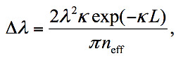 (1)
(1)
where λ is the resonance wavelength and neff is the effective refractive index of the mode guided in the fiber8.
To assess whether the π-FBG detector is appropriate for imaging applications, its spatially dependent response needs to be measured over a wide frequency band. However, this task is extremely challenging when conventional acoustic techniques are used. We therefore employ an optoacoustic method for ultrasound detector characterization16 in which a dark microscopic sphere embedded in transparent agar serves as an optoacoustic point source. In our experiment, the microscopic sphere has a diameter of approximately 100 µm and is illuminated with high power nanosecond optical pulses with a repetition rate of 10 Hz, pulse duration of approximately 8 nsec, and average power of 200 mW. The optical energy deposited in the microscopic spheres generates broadband ultrasound signals owing to the optoacoustic effect. The π-FBG detector is translated relatively to the microscopic sphere to obtain its spatially dependent acoustic response. Figure 3 shows an illustration of the optoacoustic experiment. Generally, this technique can be employed to characterize different kinds of ultrasound detectors.
Access restricted. Please log in or start a trial to view this content.
Protocol
1. Optoacoustic Characterization of the π-FBG Detector
- Preparation of a microscopic sphere suspended in agar:
- Mix agar powder (1.3% by weight) with distilled water in a glass beaker. Use a hot plate magnetic-stirrer device to heat the solution close to boiling temperature and dissolve the agar powder until the solution becomes clear and free of air bubbles. Alternatively, the agar solution may be heated using a conventional microwave with stirring performed manually using a glass stirrer. Pour the hot solution into a plastic mold, e.g. syringe with its tip cut out.
- Sprinkle a small amount of microscopic spheres on the agar solution and wait until the solution fully solidifies. Take the solid agar phantom out of the mold by pushing the plunger.
- View the phantom under a stereoscopic microscope cut a small piece of agar which contains a single microscopic sphere.
- Repeat step 1.1.1 and add to the agar solution the solid agar piece containing the single microscopic sphere.
- After solidification, cut the agar phantom under the microscope such that the microscopic sphere is located close to the phantom's surface.
- Optoacoustic measurement
- Use two v-groove fiber holders to hold the fiber tightly on both sides of the π-FBG, and connected the holder to a three dimensional (XYZ) translation computer-operated stage. Ensure that the fiber is submerged to enable the propagation of ultrasound.
- Find the approximate location of the sensing π-FBG element by illuminating different parts of the fiber with the high-power nanosecond-pulse laser beam. The optical absorption of the coating, however weak, will create a signal when the illumination is performed on the π-FBG.
- Place the agar-embedded microscopic sphere directly underneath the π-FBG. The microscopic sphere should be visible to the naked eye.
- Using the translation stage, perform a 2D scan of the π-FBG in the plane parallel to the ground to find the location where the signal from the microscopic sphere is strongest and its corresponding time delay is shortest.
- Perform last adjustments to the illumination to deliver maximum power to the microscopic sphere.
- Using the translation stage perform a 3D scan of the π-FBG and record the signal for each position.
- To obtain the spatially dependent frequency response of the ultrasound detector, perform the Fourier transform on the recorded time-domain ultrasound signal.
2. Estimation of Robustness and Sensitivity of the π-FBG Detector's Performance
- Use two v-groove fiber holders to hold the fiber tightly on both sides of the π-FBG and submerge the π-FBG.
- Place a dark plate or a graphite rod sturdily to face the π-FBG and illuminate it with the high-power nanosecond-pulse laser beam to create a strong acoustic field.
- Place a water pump inside the water tank and turn it on in order to create rapid variations in the environmental conditions.
- To estimate the robustness of the system, measure the output with the locking circuit turned both on and off. When no locking is performed, it is not possible to accurately detect the ultrasound signal.
- Turn the water pump off.
- To estimate the benefit in sensitivity due to the high coherence of the source, replace the wideband pulse laser with a low coherence source and repeat the acoustic measurement. A decrease of over an order of magnitude in sensitivity is expected when the low-coherence source is used.
Access restricted. Please log in or start a trial to view this content.
Results
Figures 4a and 4b respectively show the signals and their corresponding spectra from the microscopic sphere at a distance of 1 mm from the fiber for three offsets from the center of the π-FBG. The offsets are given in the z direction, as depicted in Figure 3. Clearly, The optical detector’s sensitivity to high frequency ultrasound (f > 6 MHz) is anisotropic and is highest when the center of the π-FBG is directly above the microscopic sphere. Despite the high acoustic ...
Access restricted. Please log in or start a trial to view this content.
Discussion
In conclusion, a new optical method for ultrasound detection is introduced, which is based on a combination of a π-FBG and pulse interferometry. The technique is especially suited for optoacoustic imaging applications owing to the transparency of the sensing element, which enables almost arbitrary object illumination patterns. In contrast, standard piezoelectric based ultrasound detectors are opaque and thus block some of the optical paths to the imaged object, leading to bulky imaging setups. The developed optical ...
Access restricted. Please log in or start a trial to view this content.
Disclosures
The authors declare that they have no competing financial interests.
Acknowledgements
D. R. acknowledges support from the German Research Foundation (DFG) Research Grant (RA 1848/1) and the European Research Council Starting Grant. V. N. acknowledges financial support from the European Research Council Advanced Investigator Award, and the BMBF's Innovation in Medicine Award.
Access restricted. Please log in or start a trial to view this content.
Materials
| Name | Company | Catalog Number | Comments |
|---|---|---|---|
| π-FBG | Teraxion Inc. | Custom made device | |
| Microscopic spheres | Cospheric LLC | BKPMS 90-106um- 10g | 100 µm polyethylene microspheres |
| Femto-second pulse laser used for interrogation | Menlo Systems GmbH | T-Light Femtosecond Laser | |
| Optical filter | Optoplex Corporation | 2-Port Optical Tunable Filter (50 GHz) | |
| Optical amplifier | Amonics | AEDFA-PM-PA-35-B-FC | Benchtop 35dB Gain Pre Amp Polarization Maintaining EDFA |
| 50/50 coupler | OZ-Optics | FUSED-22-1550-8/125-50/ 50-3S3S3S3S-3-0.5-PM | Fused 2 x 2 fiber splitter with 0.5 meter long, 3 mm OD PVC jacketed 1,550 nm 8/125μ PM fiber pigtails, 50/50 split ratio in the slow axes of PM fibers and with super FC/PC connectors on all ports. |
| Fiber holder | Thorlabs | T711/M-250 | Metric, Post-Mountable Fiber Clamp, 250 µm |
| Agar for microbiology | Sigma Aldrich | 05039-500G | |
| Nano-second pulse laser used for generating the optoacoustic signals | Opotek | VIBRANT Arrow 532 type I | |
| Graphite rod | Faber-Castell | 120700 | Faber-Castell Pencil Leads - 0.7 mm |
References
- Hunt, J. W. Ultrasound transducers for pulse-echo medical imaging. IEEE Transactions on Biomedical Engineering. 30, 453-481 (1983).
- Razansky, D. Multispectral opto-acoustic tomography of deep-seated fluorescent proteins in vivo. Nature Photon. 3, 412-417 (2009).
- Ntziachristos, V. Going deeper than microscopy: the optical imaging frontier in biology. Nature Methods. 7, 603-614 (2010).
- Wang, L. H., Hu, S. Photoacoustic tomography: In vivo imaging from organelles to organs. Science. 23, 1458-1462 (2012).
- Sethuraman, S. Photoacoustic imaging using an IVUS imaging catheter. IEEE Transactions on Ultrasonics, Ferroelectrics and Frequency Control. 54, 978-986 (2007).
- Rosenthal, A. Optoacoustic methods for frequency calibration of ultrasonic sensors. IEEE Transactions on Ultrasonics, Ferroelectrics and Frequency Control. 58, 316-326 (2011).
- Rosenthal, A. High-sensitivity compact ultrasonic detector based on a pi-phase-shifted fiber Bragg grating. Optics Letters. 36, 1833-1835 (2011).
- Beard, P. C., Mills, T. N. Extrinsic optical fibre ultrasound sensor using a thin polymer film as a low finesse Fabry-Perot interferometer. Applied Optics. 35, 663-675 (1996).
- Xiong Pernice, W. H. P., Tang, C., X, H. High Q micro-ring resonators fabricated from polycrystalline aluminum nitride films for near infrared and visible photonics. Optics Express. 20, 12261-12269 (2012).
- Zhang, E. Backward-mode multiwavelength photoacoustic scanner using a planar Fabry-Perot polymer film ultrasound sensor for high-resolution three-dimensional imaging of biological tissues. Applied Optics. 47, 561-577 (2008).
- Grün, H. Three-dimensional photoacoustic imaging using fiber-based line detectors. Journal of Biomedical Optics. 15, 021306-02 (2010).
- Avino, S. Musical instrument pickup based on a laser locked to an optical fiber resonator. Optics. Express. 19, 25057-25065 (2011).
- Rosenthal, A. Wideband optical sensing using pulse interferometry. Optics Express. 20, 19016-19029 (2012).
- Rosenthal, A. Wideband fiber-interferometer stabilization with variable phase. IEEE Photonics Technology Letters. 24, 1499-1501 (2012).
- Rosenthal, A. Spatial characterization of the response of a silica optical fiber to wideband ultrasound. Optics Letters. 37, 15-3174 (2012).
- Rosenthal, A., Razansky, D., Ntziachristos, V. Model-based optoacoustic inversion with arbitrary-shape detectors. Medical Physics. 38, 4285-4295 (2011).
Access restricted. Please log in or start a trial to view this content.
Reprints and Permissions
