This manuscript shows the fabrication process for the manufacture of dielectric elastomer soft actuators based on silicone membranes. The three key stages of production are presented in detail: blade casting of thin silicone membranes; pad printing of compliant electrodes; and the assembly of all the components.
Method Article
Fabrication Process of Silicone-based Dielectric Elastomer Actuators
In This Article
Summary
Abstract
This contribution demonstrates the fabrication process of dielectric elastomer transducers (DETs). DETs are stretchable capacitors consisting of an elastomeric dielectric membrane sandwiched between two compliant electrodes. The large actuation strains of these transducers when used as actuators (over 300% area strain) and their soft and compliant nature has been exploited for a wide range of applications, including electrically tunable optics, haptic feedback devices, wave-energy harvesting, deformable cell-culture devices, compliant grippers, and propulsion of a bio-inspired fish-like airship. In most cases, DETs are made with a commercial proprietary acrylic elastomer and with hand-applied electrodes of carbon powder or carbon grease. This combination leads to non-reproducible and slow actuators exhibiting viscoelastic creep and a short lifetime. We present here a complete process flow for the reproducible fabrication of DETs based on thin elastomeric silicone films, including casting of thin silicone membranes, membrane release and prestretching, patterning of robust compliant electrodes, assembly and testing. The membranes are cast on flexible polyethylene terephthalate (PET) substrates coated with a water-soluble sacrificial layer for ease of release. The electrodes consist of carbon black particles dispersed into a silicone matrix and patterned using a stamping technique, which leads to precisely-defined compliant electrodes that present a high adhesion to the dielectric membrane on which they are applied.
Introduction
Dielectric elastomer transducers (DETs) are soft devices that consist of an elastomeric dielectric membrane (typically 10-100 µm thick), sandwiched between two compliant electrodes, thus forming a rubbery capacitor1. DETs can be used as actuators capable of producing very large strains (up to 1,700% surface strain has been demonstrated)2, soft strain sensors3, or as soft power generators4. When used as actuators, a voltage is applied between the two electrodes. The generated electrostatic force squeezes the dielectric membrane, reducing its thickness and increasing its surface area (Figure 1)1. In addition to actuators, the same basic structure (thin elastomer membrane and stretchable electrodes) can be used as strain sensor or energy harvesting devices, taking advantage of the change of capacitance induced by mechanical deformation. The large strains generated by dielectric elastomer actuators (DEAs) and their soft and compliant nature has been used for many applications, such as electrically tunable lenses5, rotary motors6, deformable cell-culture devices7, and propulsion of a bio inspired fish-like airship8.
Most DETs reported in the literature use a proprietary acrylic elastomer film from 3M named VHB as dielectric elastomer membrane, because it has been showed to exhibit very large actuation strains1. The availability of this material in film form is also a key factor in its wide use for DET applications, even though (actuation strain set aside), it has a number of important drawbacks, such as mechanical losses and viscoelastic creep that limit its response speed, a small operating temperature range, and a propensity for tearing. In comparison, silicone elastomers can also be used as dielectric membrane for DETs, leading to devices with a response speed 1,000 times faster than acrylic elastomers, due to their much reduced mechanical losses9. In addition, they are available in a large range of hardnesses, which gives additional design freedom. However, silicones are usually sold in a viscous base form, which must be applied in thin-membranes to be used for DETs. However, this provides yet an additional degree of freedom, as the thickness of the membrane can be freely chosen and is not imposed by the manufacturer, as is the case for premade films.
This protocol shows the fabrication of a dielectric elastomer actuator. However, it can be also applied with little to no modification for the fabrication of dielectric elastomer transducers in a larger sense, including energy harvesting devices and strain sensors. We present here a method for large area (A4) casting of thin (10-100 µm) silicone films on flexible PET substrates coated with a water-soluble sacrificial layer. The sacrificial layer reduces the forces required to separate the silicone membrane from the substrate, thus reducing the mechanical deformation of the membrane during release. Deformation of the film can lead to anisotropic mechanical properties due to stress-induced softening (Mullins effect)10 and should therefore be avoided. The electrodes are the second key component of a DET. Their role is to distribute the electrical charges on the surface of the elastomeric membrane. To produce a reliable actuator, the electrodes must be able to withstand repeated strains higher than 20% without cracking, degrading, delaminating, or losing conductivity; furthermore, they must be compliant as to not mechanically stiffen the structure11. Among the different techniques that exist to make compliant electrodes, hand-applied carbon black particles or carbon grease are the two most widely used methods11. However, these methods have quite a few disadvantages: application by hand prevents miniaturization of devices, leads to non-reproducible results and is time-consuming. In addition, carbon powder or grease does not adhere to the membrane and electrodes produced by this method are subject to wear and mechanical abrasion. Also, in the case of grease, the binding fluid can diffuse into the dielectric membrane and modify its mechanical properties. The lifetime of un-encapsulated carbon powder or grease electrodes is consequently quite short. Here, we present the patterning of compliant electrodes by a stamping technique named pad printing in which a precise design is transferred to the membrane via a soft silicone stamp, thus allowing to rapidly and reproducibly pattern precise electrodes, with features down to 0.5 mm. The applied solution consists of a mixture of carbon black in a silicone matrix, which is cross-linked after application, thus leading to cured electrodes with strong adhesion to the elastomeric membrane, making them very resilient and resistant to mechanical abrasion and wear.
The following protocol describes all the steps required to manufacture fast and reliable DEAs with precisely patterned compliant electrodes. This includes membrane casting and prestretching, patterning and alignment of the electrodes, assembly, electrical connection and testing. For the purpose of the video, we fabricate a simple in-plane actuator with a gear-shaped electrode, as shown in Figure 2. The actuator consists of a thin silicone membrane stretched over a membrane holder, on which two compliant electrodes are patterned. An actuator frame is then inserted to provide electrical contact to the bottom electrode. Figure 3 shows an exploded view of the assembly with the different components of the actuator. Although the device realized in the video has no practical application beyond demonstrating the basic principle of DEAs, different actuators aimed at specific applications have been made using the exact same process, such as soft grippers, tunable lenses, tunable mm-wave phase shifters, etc.
Protocol
1. Silicone Membrane Production
- Sacrificial layer casting
- Cut a 400 mm long sheet of high quality 125 µm-thick PET from the roll.
- Prepare sacrificial solution (5% poly acrylic acid in isopropanol by weight): mix together 32 g of isopropanol and 8 g of poly acrylic acid solution (25% in water) in a 50 ml plastic tube. Shake well.
- Clean the PET substrate with lint free wipes impregnated with isopropanol.
- Clean the vacuum table with lint free wipes impregnated with isopropanol.
- Lay the PET substrate on the vacuum table and turn on the vacuum pump.
- Visually inspect the vacuum table to ensure that no large dust particles are trapped between the vacuum table and the PET substrate. Repeat the previous cleaning steps if dust particles are identified.
- Clean the top surface of the PET substrate with lint free wipes impregnated with isopropanol.
- Place the profile rod applicator on the automatic film coater and set coating speed to 5 mm/sec.
- Put 2 ml of sacrificial layer solution in front of the profile rod and start the coater machine.
- When the profile rod has reached the end of the PET substrate lift it out of the coater and clean it by wiping with a lint-free wipe soaked in hot water.
- Retract the film applicator but leave the vacuum pump running and leave the PET substrate on the vacuum plate. Let the layer dry in air for 2 min.
- Silicone membrane casting
- Preheat the oven to 80 °C.
- Add 15 g of silicone base and 1.5 g of cross-linker to a mixing pot. Add 10 g of silicone solvent to decrease the viscosity.
- Mix the silicone mixture with a planetary mixer. Use a 2 min mixing cycle at 2,000 rpm plus a 2 min degassing cycle at 2,200 rpm.
- Set the height of the universal applicator to 225 µm. Place the applicator at top of the PET sheet and set the film applicator speed to 3 mm/sec.
- Transfer 15 ml of silicone mixture from the mixing pot on to the PET substrate with a syringe.
- Start the automatic applicator to apply silicone over the complete PET substrate (Figure 4A).
- Turn off the pump and wait for 5 min to let the solvent evaporate from the cast layer.
- Transfer the membrane onto a glass plate and place in the oven for 30 min at 80 °C.
- Clean the applicator and vacuum plate with lint-free wipes impregnated with isopropanol.
- After 30 min, remove the membrane from the oven, leave to cool down at RT for a further 5 min and cover it with a thin PET foil to protect the surface from contaminants.
2. Release and Prestretching of Elastomeric Membranes
- Prestretch support fabrication
- Cut an A4-size rectangle from the roll of dry silicone transfer adhesive.
- Remove one of the protective covers from the dry silicone transfer adhesive and manually apply the adhesive onto an A4 transparency film, taking care to avoid the formation of bubbles during application.
- Cut the prestretch support pattern into the adhesive-covered transparency film using a computer numerical control (CNC) laser engraver (Figure 4B) according to manufacturer’s protocol.
- Membrane support fabrication
- Cut a 500 mm by 290 mm rectangle in the roll of dry silicone transfer adhesive.
- Peel away one of the protective covers from the dry silicone transfer adhesive and laminate the foil onto a 3 mm thick poly(methyl methacrylate) (PMMA) plate.
- In the PMMA frame, cut rings of 52 mm outside diameter and 44 mm inside diameter that will serve as membrane holders.
- Membrane release
- Cut the cast silicone membrane/PET substrate sandwich from step 1 into circles 55 mm in diameter using a CNC laser engraver (Figure 4B) according to manufacturer’s protocol and peel away the protective film.
- Fix the laser-cut prestretch support onto the cut silicone membrane circle adhesive side down, such that the adhesive is in contact with the silicone surface (Figure 4C).
- Prepare a bath of boiling water and submerge the assembly (silicone membrane and adhesive support) into it.
- Whilst submerged, gently and slowly peel the PET substrate away from the silicone membrane (Figure 4D).
- Remove the silicone membrane from the water bath and let it dry in air or use a nitrogen gun to speed-up the drying process.
- Membrane thickness measurement and prestretch
- Measure the thickness of the membrane with a transmission interferometer according to manufacturer’s protocol.
- Set the prestretcher to a diameter of 45 mm, and place the prestretch support-silicone membrane on the stretcher fingers, adhesive side down.
- Cut the prestretch support between the stretcher fingers (Figure 4E).
- Increase the diameter of the prestretcher to 58.5 mm to equi-biaxially prestretch the membrane by a factor 1.3 (30% prestretch) by rotating the prestretcher annulus anti-clockwise (Figure 5).
- Remove the cover film from the PMMA membrane holder exposing the adhesive and stick the PMMA membrane holder onto the prestretched membrane surface (Figure 4F).
- Cut around the membrane holder to remove the prestretched membrane from the stretcher.
- Measure the final thickness of the prestretched membrane with a transmission interferometer.
3. Patterning Compliant Electrodes by Pad Printing
- Conductive ink preparation
- In a 125 ml plastic mixer container, place 0.8 g carbon black with 16 g isopropanol and 6 steel balls of 12 mm diameter. Mix at 2,000 rpm for 10 min in a planetary mixer.
- Add 4 g silicone elastomer part A, 4 g part B, and 16 g isooctane. Mix at 2,000 rpm for 10 min in a planetary mixer.
- Setup of the pad printing machine
- Install the cliché with the desired electrode pattern on the magnetic block (Figure 4G).
- Fill the inkcup with the conductive silicone-based ink.
- Place the cliché block (cliché fixed on the magnetic block) on top of the ink-filled inkcup and install the assembly in the machine.
- Fix the silicone pad on the machine.
- Alignment
- Place the aligner plate (Figure 4H) on the printer base.
- Initiate a printing cycle on the pad printing machine, which will apply the electrode design on the aligner plate according to manufacturer’s protocol.
- Visually inspect the overlap of the printed electrode and the etched reference structure of the aligner plate. Move the x-y-θ stage to correct for any misalignment.
- Clean the aligner plate and print another electrode.
- Visually inspect the alignment with the reference structure and continue moving the platform position and printing electrodes until you obtain a perfect superposition of the printed pattern on the reference structure (Figure 4H).
- Printing compliant electrodes
- Place a prestretched membrane on the printer base.
- On the pad printing machine, launch a printing cycle to stamp the electrode on the membrane top side (Figure 4I). Stamp the membrane twice to ensure a sufficient electrode thickness of about 4 µm.
- Remove the membrane from the printer base, place the next prestretched membrane on the printer base and repeat the printing process until all prestretched membranes are stamped.
- Place the membranes with the stamped electrode in an oven at 80 °C for 30 min.
- After 30 min, remove the membranes from the oven.
- Place one of the printed membranes upside down on the printer base, exposing the membrane back side.
- Initiate a printing cycle to pattern the bottom electrode.
- Remove the membrane from the printer base, place the next membrane on the printer base and repeat the printing process until all membranes are stamped on both sides.
- Place the membranes in the oven at 80 °C for 30 min to cross-link the bottom electrode.
4. Creating Electrical Connections
- Cut actuator frames that will serve as holding frame for the actuator in the same PMMA plate used for the membrane holder (c.f. 2.2) using a CNC laser engraver.
- Peel-off the backing of the adhesive on the top of the actuator frame.
- Apply an 18 mm x 2.5 mm piece of conductive tape on the part of the actuator frame that will come into contact with the bottom electrode, and fold it to the side of the frame to provide the electrical contact (Figure 3).
- Slide the actuator frame inside the membrane holder, and gently press the membrane with fingers to stick it to the adhesive of the actuator frame.
- With a scalpel, cut the membrane at the border between the membrane holder and actuator frame and remove the former.
- Apply a second piece of 18 mm x 2.5 mm conductive tape on the contact zone of the top electrode.
- Place a wire on each piece of conductive tape to make an electrical connection. Connect the two wires to a high voltage source, and apply a 2 Hz square signal of 2 kV amplitude. Observe the periodic expansion of the device.
Results
Silicone membrane casting
Once the silicone membranes are released from the PET substrate and are freestanding on a frame (at the end of step 2.2), their thickness can be measured, for example by transmission interferometry. Figure 6 shows the thickness homogeneity of a silicone layer across the width of the 200 mm PET substrate for 3 different effective gap heights (50, 100 and 150 µm) at a casting speed of 1 mm/sec (note that because the applicator is wider than the PET substrate, the feet of the applicator rest on the vacuum and not on the PET substrate itself, as can be seen in Figure 4A. The effective gap between the applicator and the substrate is therefore equal to the applicator height minus the thickness of the PET substrate. For example a PET substrate of 125 µm and an applicator height of 225 µm, as used in the protocol, leads to an effective gap of 100 µm). For the 50 µm effective gap height, there is a clear height difference between the left and right side of the silicone layer. This is because the height of the applicator must be set manually on the left and right side, and some error is unavoidable. However with careful setting of the applicator, we generally obtain membranes with a thickness standard deviation of less than 1 µm, which is the case for the 100 µm effective gap height (σ=0.81 µm). When the applicator height becomes too large, waviness starts to appear on the membrane, caused by the evaporation of the solvent in the silicone mixture, as is visible in the membrane cast with an effective gap of 150 µm (Figure 6).
The relation between the obtained dry film thickness and the applicator height depends on the silicone mixture and the speed of casting. The silicone mixture used in this article consists of a 2-parts silicone, and a solvent to decrease the viscosity of the mixture. As the solvent evaporates from the membrane before curing, an estimate of the film thickness can be obtained by multiplying the effective gap height by the volume fraction of solids in the silicone mixture. However, there are dynamic effects at the trailing of the applicator, leading the creation of a meniscus and a thinner thickness than expected. The relation between the gap height and the resulting dry membrane thickness depends on the casting speed, applicator height, and by the applicator shape. Figure 7 shows the results of an experiment where membranes were cast at different speeds and heights to show how these parameters affect dry film thickness. It can be seen that casting at high speeds leads to thinner membranes, and that the effect of speed becomes more pronounced as the gap height increases.
Actuation Performance
The actuator fabricated here is characterized by measuring the outside diameter of the cog-like electrode as a function of applied voltage. A camera on a fixed stand is used to take pictures of the actuator as the voltage is increased. The images are analyzed with an image processing script (Vision, National Instruments) to quantify the expansion of the actuator. This was done by fitting a circle to the outside perimeter of the cog like electrode (Figure 8). The increase in diameter of the circle from the relaxed state is presented as diametral stretch (i.e., the actuated diameter divided by the diameter of the actuator when relaxed). The results of two separate actuators of identical thickness (34.5 µm) are shown in Figure 8. Both devices perform similarly with diametral stretch of 10% at an actuation voltage of 4 kV.
The response speed of the actuator was measured by applying a 2 Hz square signal of 3 kV, leading to a strain of about 4%. The expansion of the actuator was filmed with a high-speed camera with a time resolution of 0.25 msec. A rising edge was captured, with 200 frames (50 msec) before the voltage trigger, and 200 frames after. The images where then analyzed to extract the time-dependent deformation (Figure 9). The rise time (time needed to reach 90% of the final deformation) is 3.75 msec, and there is no observable viscoelastic creep before and after the voltage step, unlike what is observed when acrylic elastomers are used as membranes, for which rise times of several hundreds of seconds are usually observed12.
Application of the process flow to other devices
The actuator manufactured in this article demonstrates our fabrication process, as well as the basic functioning principle of a DEA with an increase in surface area of the electrodes upon application of a voltage, and is therefore a good illustration for this tutorial. However, this actuator has no specific purpose other than demonstrating the actuation principle of a DEA. Nevertheless, the process presented here is very versatile and can be used to manufacture a wide variety of soft transducers aimed at specific applications. We present here a few selected examples of applications that we developed based on actuators fabricated using the presented methodology.
Soft bio-inspired tunable lenses have been fabricated (Figure 10A). These are capable of changing focal length by 20% in less than 200 µsec9. The device can be actuated for more than 400 million cycles without noticeable decrease in actuation performance, which shows that the combination of adequate materials and good fabrication processes result in DEAs with fast response speeds and long lifetimes. Lenses of similar geometry but made using the widely used commercial acrylic elastomer VHB have a bandwidth more than 3 orders of magnitude smaller9.
Patterning the compliant electrodes with pad printing allows making very precisely-defined electrodes, thus enabling the fabrication of independent small-scale electrodes on the same membrane. This is for example demonstrated through the fabrication of a DEA-based rotary motor comprising three electrically independent electrodes (Figure 10B). The axis and proof mass at the center of the motor can spin at 1,500 rpm13. The motor concept has been pushed further to show that pad printing can also produce reliable actuators. A self-commutating rolling robot was built to run laps along a circular track (Figure 10C). The robot travelled more than 25 km at an average speed of 15 cm/sec13.
Other applications that have been produced with the present process (or slight variations thereof) include deformable cell culture systems14, Dielectric elastomer generators15, multi-segment soft grippers16, or tunable mm-wave radio frequency phase shifters17.
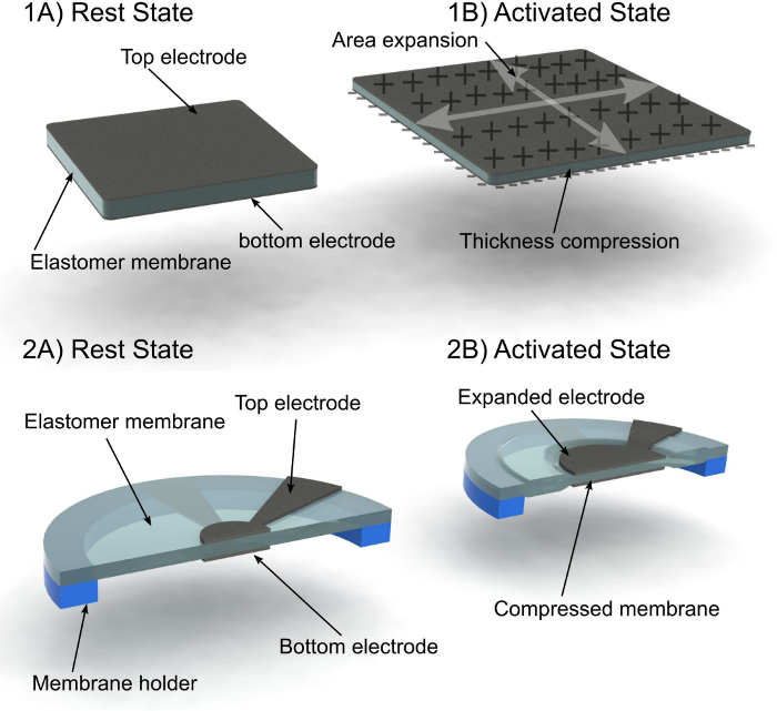
Figure 1. Basic principle of dielectric elastomer actuators. Top: (1A) In its most simple form, a DEA consists of a soft elastomer membrane sandwiched between two compliant electrodes. (1B) When a DC voltage is applied between the electrodes, the electrostatic charges brought on the electrodes create a compressive stress that squeezes the membrane, leading to a thickness reduction and a surface expansion. Bottom: (2A) the actuator described in the protocol consists of a membrane stretched on a frame. Circular electrodes are on either side of the membrane with extensions to the border of the membrane to allow for electrical connections. The active area is the zone where the two electrodes overlap, i.e., the circle at the center. (2B) When a voltage is applied, the electrostatic force compresses the membrane. This causes a decrease of the membrane thickness in the active area, and an increase of the surface of the electrode. Because the membrane is prestretched, the passive zone around the electrode relaxes to accommodate the expansion of the central active region. Please click here to view a larger version of this figure.
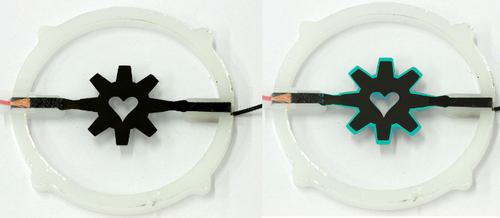
Figure 2. Demonstrator actuator fabricated in this protocol. Left: finished device comprising a stretched silicone membrane fixed on a frame, a pair of compliant electrode patterned on both sides of the membrane, and electrical connections. Right: composite picture showing the rest state (black) and activated state (cyan). A 10% increase in the diameter of the structure is observed with 4 kV applied across the electrodes. Please click here to view a larger version of this figure.
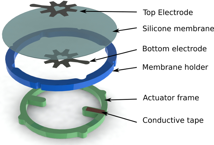
Figure 3. Exploded view of the actuator. The different components that form the actuator manufactured in the video. The membrane holder retains the prestretched silicone membrane and is used to manipulate the membrane during the electrode printing step. Once the electrodes are cured, the actuator frame is inserted inside the membrane holder and provides both a structural frame to hold the actuator, and an electrical contact to the bottom electrode. Once the membrane is fixed to the actuator frame, the membrane holder can be removed. Please click here to view a larger version of this figure.
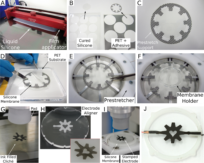
Figure 4. Overview of fabrication process. (A) Casting of silicone membranes using an automatic film applicator coater. (B) Laser cutting of cured silicone membrane and prestretch supports. (C) Placing of silicone membrane on prestretch support. (D) Releasing of silicone membrane from PET substrate by dissolving of PAA sacrificial layer in hot water. (E) Cutting of prestretch support sections linking the fingers. (F) Prestretch and adhering of membrane holder to the membrane surface. (G) Cliché filled with conductive ink. (H) Laser etched electrode aligner, inset figure shows example of a well-aligned electrode.(I) Silicone membrane with stamped electrode. (J) Finished device. Please click here to view a larger version of this figure.
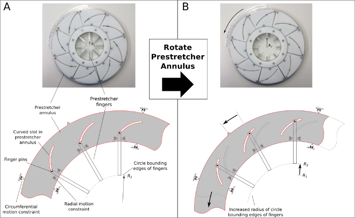
Figure 5. Operating principle of the membrane prestretcher. (A) Several metal fingers are attached to a plastic annulus and are constrained to move in a linear (radial) fashion along their length. The annulus is constrained to move circumferentially. The plastic annulus has several curved slots machined into it, into which the metal pins of the fingers reside. Radius of a circle bounding the edge of the fingers is R1. (B) The prestretcher annulus is rotated counter-clockwise, the fingers translate simultaneously, increasing the radius of the circle bounding the finger edges from R1 to R2. Please click here to view a larger version of this figure.
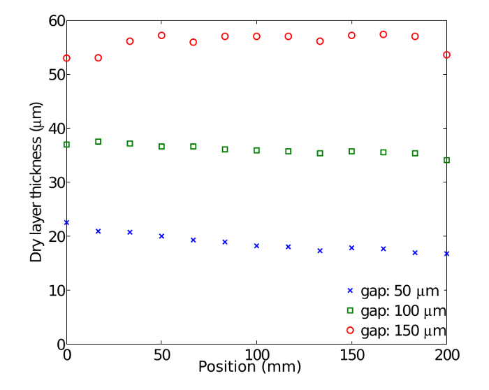
Figure 6. Thickness homogeneity of the casted silicone layers. Thickness measurement of the cured silicone membrane across the width of the 200 mm PET substrate, for three different gap settings of the applicator. The casting speed is 1 mm/sec. Please click here to view a larger version of this figure.
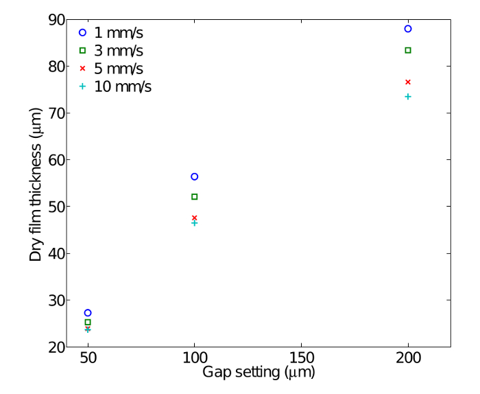
Figure 7. Dry film thickness as a function of casting parameters. Dry film thickness obtained for different applicator heights and speed for a silicone-solvent mixture with 62% solid content by volume. A higher speed leads to thinner membranes for equal applicator settings, and the influence of speed increases with increasing membrane thickness. Please click here to view a larger version of this figure.
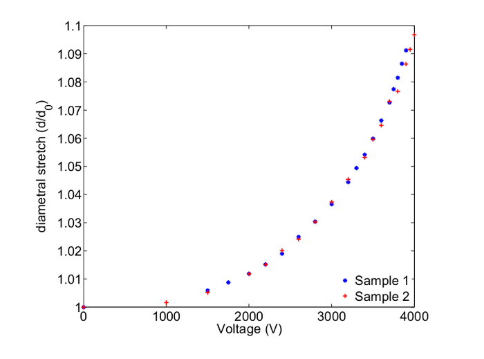
Figure 8. Actuation of the demonstrator. Outside diametral stretch as a function of the applied voltage for two devices with a thickness (after prestretch) of 34.5 µm. An increase of diameter of about 10% is observed at the maximal applied voltage. Please click here to view a larger version of this figure.
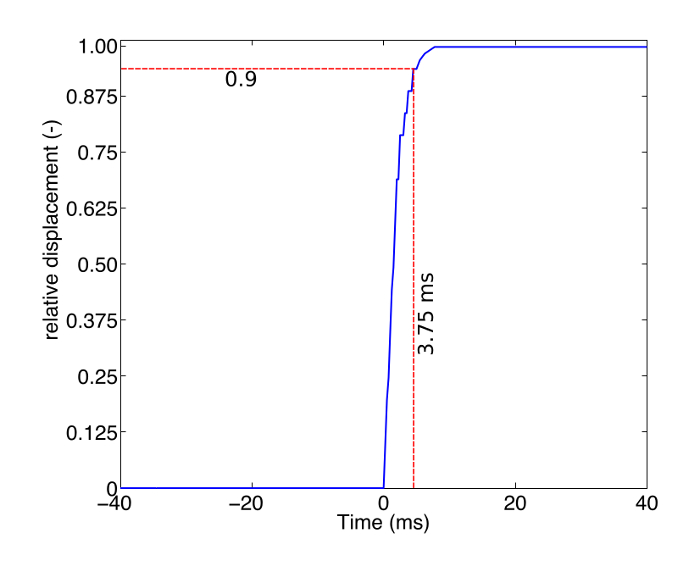
Figure 9. Strain response to a voltage step input. A square, 3 kV 2 Hz signal is applied to the device, generating a strain of about 4% (see Figure 8). The area expansion is observed with a high speed camera at 4,000 frame per second. It takes less than 4 msec for the actuator to reach 90% of its final dimension. Before and after the transition, the dimension of the actuator remain stable and do not show viscoelastic creep. Please click here to view a larger version of this figure.
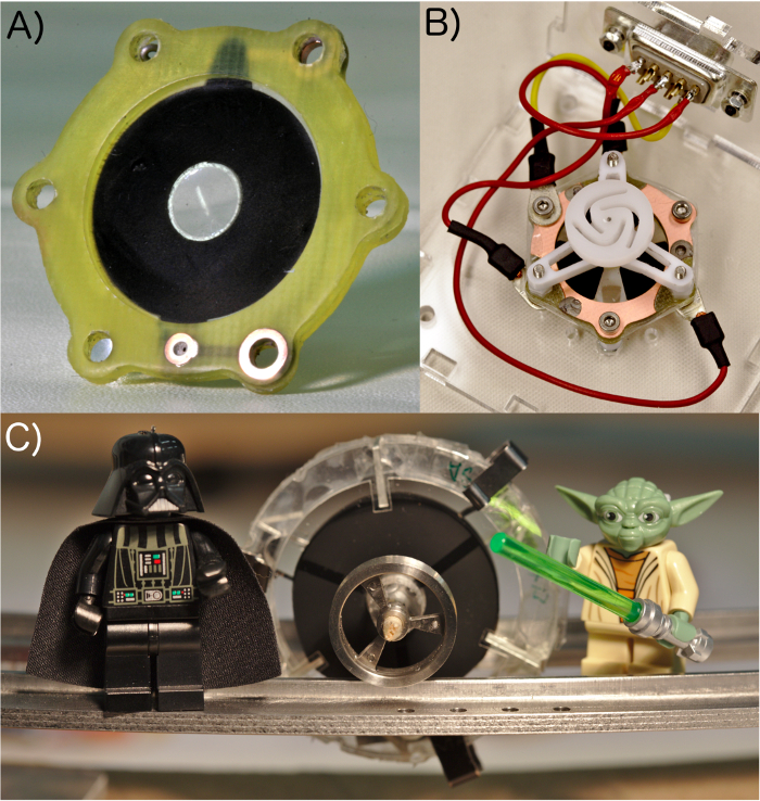
Figure 10. Dielectric elastomer actuators made with the presented process flow. Three examples of dielectric elastomer actuators made by following the methodology described in this document. (A) Fast and soft tunable lens capable of changing its focal length by 20% in less than 200 µsec. (B) Rotary elastomer micro-motor capable of spinning at 1,500 rpm. (C) Self-commutating rolling robot. Please click here to view a larger version of this figure.
Discussion
The fabrication process can be summarized as follows. Start by applying a water-soluble sacrificial layer on the PET substrate used for the casting of the membrane. This avoids excessive deformation during the release process that can potentially damage the membrane. The silicone is then casted in a thin layer and cured in an oven. The A4 PET sheet with the silicone coating is cut into circular discs of 55 mm diameter, and stuck to flexible prestretch supports. The prestretch supports are used to manipulate the membrane during the sacrificial layer release and prestretching steps. To separate the membrane from the PET substrate, it is dipped in hot water to dissolve the sacrificial layer. This process allows the membrane to be freed without having to pull on it significantly. Once the membrane is freestanding, it can be prestretched. Prestretching consists in mechanically stretching the membrane in-plane before fixing it on holding frames. This step generates internal tensile forces in the membrane and is necessary for in-plane dielectric elastomer actuators, such as the demonstrator being produced here. In the protocol, we use equi-biaxial stretching, i.e., an equal stretching value in both in-plane directions. However, depending on the application, different prestretching configurations can be used, such as uniaxial (stretching only along x or y, while the membrane is allowed to relax in the other direction), or anisotropic (different values along x and y).
A technique called pad printing is used to precisely pattern a compliant electrode on the prestretched silicone membrane, which allows to precisely define mm-size electrodes on the membrane. In this process, ink is applied with a doctor blade on a cliché (a steel plate on which the design to be printed is etched, and subsequently picked up from the cliché by a smooth silicone stamp before being transferred to the membrane13). Every design requires its own cliché. These can be ordered from specialized companies, which produce them from an electronic drawing of the geometry. To make a stretchable conductive electrode, disperse carbon black in a silicone matrix by shear forces using ball milling, which is a well-known technique to break the agglomerations of carbon black and homogenously disperse the powder in a polymeric matrix18,19.
When printing, it is important that the design is printed with a precise positioning and orientation relative to the membrane frame. To do so, use a precision x-y-θ stage and an aligner. The aligner is a piece of PMMA in the same shape as the membrane frame and has the electrode design etched on to its surface using a CNC laser engraver. Before printing on the membrane we print on the alignment plate to check the alignment. If the printed design does not match the etched design we adjust the x-y-θ stage until the two designs overlap (Figure 4H). In the protocol, the top and bottom electrode have the same design, so the pad printing machine can be left untouched between the applications of the two electrodes. However, in some cases, the electrodes geometries are different for the top and bottom electrode. In that case, while the membranes are in the oven for the curing of the top electrode (i.e., between steps 3.4.3 and 3.4.4), it is necessary to remove the cliché block (the assembly consisting of the cliché held in place on a magnetic block) with the inkpot from the pad printing machine. Then, the installed cliché must be exchanged for the one with the bottom electrode design. Because the cliché block has been moved, it is necessary to conduct a new alignment procedure (step 3.3) using an aligner plate etched with the design of the second electrode. Once both electrodes are applied, they need to be connected to an external driving circuit that supplies the charges for actuation. There are different solutions for making the electrical connections between the compliant electrodes and the driving electronics. Here, a method well-suited for prototyping is shown, using adhesive-covered frames and conductive tape (Figure 3). For batch production, the use of printed circuit boards with copper pads contacting the electrodes is a better alternative (see Figure 10A for an example of a device made with a commercial PCB).
Use commercial equipment or products for most of the steps of the process flow. The two exceptions are the measurement of the thickness of the silicone membranes and the prestretching steps. For the thickness measurement, use a homemade white light transmission interferometer consisting of a collimated white light source (spot size < 1 mm) traversing the membrane and collected by a spectrometer. The period of the interference fringes of the transmitted light intensity as a function of wavelength is used to calculate the thickness of the membrane20. Note that other methods can be used to measure the thickness, but they must be non-destructive, and ideally contactless to avoid deforming the very thin membrane. For the prestretching of the membranes, use a homemade radial prestretcher, which consists of 8 metallic fingers which can be displaced radially. To prestretch a membrane, the fingers are moved inwards so that the prestretch support can be stuck to the fingers of the stretcher (Figure 4E). To prestretch the membrane, the fingers are moved outwards, thus effectively increasing the diameter of the silicone membrane, leading to equi-biaxial prestretching of the membrane. The eight fingers are connected to an annulus, whose rotation defines the radial separation of the fingers (Figure 5).
Having an efficient and well-established process flow such as the one presented here is important to manufacture reproducible devices that are robust and reliable. Compared to buying pre-made films, casting thin elastomer membranes gives much design freedom, as it allows choosing and tailoring the properties of the membranes to the application. For example in the case of silicone elastomers, the hardness and elongation at break can be chosen by selecting products with different chain length and density of cross-linking, and the thickness can be varied by adjusting the casting process. The latter point allows for example to choose final membrane thickness and prestretch independently, which is not possible with pre-made films.
The ability to precisely pattern the electrode on a small scale (cm to sub-mm) is also an important requirement for DEAs, as most devices consist of active and passive zones on the same membrane. This implies that the electrode shape must be precisely defined on the membrane. In addition, as electrodes must be applied on both sides of the membrane, it is necessary to align the two electrodes relative to each other: in addition to a precisely defined shape, the electrodes must also be precisely positioned on the membrane. The stamping process presented here fulfills these two requirements. Moreover, pad printing is a fast process, as only a few seconds are required to print an electrode, and actuators can easily be batch-processed using this method. Unlike the widely used carbon grease or loose powder electrodes applied manually, our approach leads to precisely defined electrodes that present a strong adhesion to the membrane on which they are applied. They are very resistant to wear, and cannot be delaminated from the membrane13. Despite the fact that pad printing is a contact method, it can be used to apply ink on thin and fragile silicone membranes, because the only part coming in contact with the membrane is a soft silicone stamp. However, there is some unavoidable stiction between the stamp and the membrane, which causes a slight deformation of the membrane once the stamp moves back upwards. If the membrane is too thin, this can lead to the rupture of the membrane. This effectively limits the application of the pad printing method to membranes thicker than 10 µm. For thinner membranes, non-contact patterning methods should be used, such as inkjet printing.
Although DEAs have been studied for more than 15 years, most of today’s DEAs are still based on ready-made polyacrylate films combined with hand-applied grease electrodes. These hand made methods have caused DEAs to remain mostly at the state of lab prototypes, with limited adoption by industry, despite the interesting performance of DEAs in terms of strain and power consumption. Although reliable fabrication processes have already been published, they concern the manufacture of unprestretched, stacked contractile actuators obtained with dedicated automated setups21,22. The process flow we present here is a versatile all-purpose process that describes all of the important steps necessary to fabricate a DEA, and which can easily be applied to fit a defined target application.
Disclosures
The authors have nothing to disclose.
Acknowledgements
This work was partially funded by the Swiss National Science Foundation, grant 200020-153122. The authors wish to thank the member’s of our soft transducers group – past and present – for their contribution to the refining of our fabrication process flow.
Materials
| Name | Company | Catalog Number | Comments |
|---|---|---|---|
| High quality PET substrate, 125 μm thick | DuPont Teijin | Melinex ST-506 | low surface roughness and absence of defects |
| Isopropanol 99.9% | Droguerie Schneitter | ||
| Poly(acylic acid) solution (25%) | Chemie Brunschwig | 00627-50 | Mw=50 kDa |
| Automatic film applicator | Zehntner | ZAA 2300 | with vacuum table |
| Profile rod applicator | Zehntner | ACC378.022 | 22.86 μm |
| Oven | Binder | FD 115 | |
| Dow Corning Sygard 186 silicone kit | Dow Corning | Sylgard 186 | silicone used for casting membranes |
| Dow Corning OS-2 silicone solvent | Dow Corning | OS2 | environmentally-friendly solvent. Mixture of 65% Hexamethyldisiloxane and 35% Octamethyltrisiloxane |
| Thinky planetary mixer | Thinky | ARE-250 | |
| container PE-HD 150 ml | Semadeni | 1972 | Container to mix the silicone for the membrane |
| Medical grade 125 ml PP wide mouth jar with cap | Thinky | 250-UM125ML | Container to mix the ink |
| Bearing-Quality steel balls 12 mm | McMaster-Carr | 9292K49 | |
| Universal applicator with adjustable gap | Zehntner | ZUA 2000.220 | |
| Transparency film for overhead projector | Lyreco | 978.758 | |
| Dry silicone transfer adhesive (roll) | Adhesive Research | Arclear 8932 | |
| poly(methyl methacrylate) plate 500 mm x 290 mm x 3 mm | Laumat | Plexi 3mm | |
| Prestretching rig | "home made" | ||
| USB spectrometer for visible light | Ocean Optics | USB4000-VIS-NIR | Spectrometer for the thickness measurement |
| Tungsten halogen white light source | Ocean Optics | LS-1 | Light source for the thickness measurement |
| 400 micrometer optical fiber | Ocean Optics | QP400-2-VIS-NIR | Optical fiber on the spectrometer side for the thickness measurement |
| 600 micrometer optical fiber | Ocean Optics | P600-2-VIS-NIR | Optical fiber on the light source side for the thickness measurement |
| Carbon black | Cabot | Black Pearl 2000 | |
| Silicone Nusil MED-4901 | Nusil | MED-4901 | silicone used in conductive ink |
| Pad-printing machine | TecaPrint | TCM-101 | |
| Thin steel cliché 100 mm x 200 mm | TecaPrint | E052 100 200 | Steel plate etched with the design you need to print. The etching is performed by the company selling the cliché. |
| 96 mm inkcup | TecaPrint | 895103 | Component of the pad printing machine in which the ink is contained |
| Soft silicone 30 mm printing pad | TecaPrint | T-1013 | Printing pad for the pad printing machine |
| 60 W CO2 Laser engraving machine | Trotec | Speedy 300 | To cut frames and foils |
| Carbon conductive tape | SPI supplies | 05081-AB | For electrical connections to the electrodes |
| 4 channels 5 kV EAP controller | Biomimetics laboratory | low power high voltage source to test the actuators. http://www.uniservices.co.nz/research/centres-of-expertise/biomimetics-lab/eap-controller |
References
- Pelrine, R., Kornbluh, R., Pei, Q., Joseph, J. High-speed electrically actuated elastomers with strain greater then 100%. Science. 287 (5454), 836-839 (2000).
- Keplinger, C., Li, T., Baumgartner, R., Suo, Z., Bauer, S. Harnessing snap-through instability in soft dielectrics to achieve giant voltage-triggered deformation. Soft Matter. 8 (2), 285-288 (2012).
- Böse, H., Fuss, E. Novel dielectric elastomer sensors for compression load detection. Proc. of SPIE. 9056, 905614(2014).
- Koh, S., Keplinger, C., Li, T., Bauer, S., Suo, S. Dielectric Elastomer Generators: How Much Energy Can Be Converted? IEEE. ASME. Trans. Mechatron. 16 (1), 33-41 (2012).
- Carpi, F., Frediani, G., Turco, S., De Rossi, D. Bioinspired Tunable Lens with Muscle-Like Electroactive Elastomers. Adv. Funct. Mater. 21 (21), 4152-4158 (2011).
- Anderson, I., et al. A thin membrane artificial muscle rotary motor. Appl. Phys. A Mater. Sci. Process. 98 (1), 75-83 (2010).
- Akbari, S., Shea, H. R. An array of 100um x 100um dielectric elastomer actuators with 80% strain for tissue engineering applications. Sens. Actuators A-Phys. 186, 236-241 (2012).
- Jordi, C., et al. Large planar dielectric elastomer actuators for fish-like propulsion of an airship. Proc. SPIE. 7642, 764223(2010).
- Maffli, L., Rosset, S., Ghilardi, M., Carpi, F., Shea, H. Ultrafast all-polymer electrically tuneable silicone lenses. Adv. Funct. Mater. 25 (11), (2015).
- Rosset, S., Maffli, L., Houis, S., Shea, H. R. An instrument to obtain the correct biaxial hyperelastic parameters of silicones for accurate DEA modeling. Proc. SPIE. 9056, 90560M(2014).
- Rosset, S., Shea, H. R. Flexible and stretchable electrodes for dielectric elastomer actuators. Appl. Phys. A Mater. Sci. Process. 110 (2), 281-307 (2013).
- Rosset, S., O’Brien, B., Gisby, T., Xu, D., Shea, H. R., Anderson, A. Self-sensing dielectric elastomer actuators in closed-loop operation. Smart Mater. Struct. 22 (10), 104018(2013).
- Rosset, S., Shea, H. Towards fast, reliable, and manufacturable DEAs: miniaturized motor and Rupert the rolling robot. Proc. SPIE. 9430, (2015).
- Poulin, A., Rosset, S., Shea, H. Toward compression of small cell population: Harnessing stress in passive regions of dielectric elastomer actuators. Proc. SPIE. 9056, 90561Q(2014).
- McKay, T., Rosset, S., Anderson, I., Shea, H. Dielectric elastomer generators that stack up. Smart Mater. Struct. 24 (1), 015014(2015).
- Araromi, A., et al. Rollable Multisegment Dielectric Elastomer Minimum Energy Structures for a Deployable Microsatellite Gripper. IEEE. ASME. Trans. Mechatron. 20 (1), 438(2015).
- Romano, P., Araromi, O., Rosset, S., Shea, H., Perruisseau-Carrier, J. Tunable millimeter-wave phase shifter based on dielectric elastomer actuation. Appl. Phys. Lett. 104 (2), 024104(2014).
- Awasthi, K., Kamalakaran, R., Singh, A., Srivastava, O. Ball-milled carbon and hydrogen storage. Int. J. Hydrogen Energy. 27 (4), 425-432 (2002).
- Leong, C. K., Chung, D. Carbon black dispersions as thermal pastes that surpass solder in providing high thermal contact conductance. Carbon. 41 (13), 2459-2469 (2003).
- Transmission Measurements of Polymer Thin Films. Ocean Optics application note. , Available from: http://oceanoptics.com/wp-content/uploads/App-Note-Transmission-Measurements-of-Polymer-Thin-Films.pdf (2014).
- Lotz, P., Matysek, M., Schlaak, H. Fabrication and application of miniaturized dielectric elastomer stack actuators. IEEE. ASME. Trans. Mechatron. 16 (1), 58-66 (2011).
- Tepel, D., Hoffstadt, T., Maas, J. Automated manufacturing process for DEAP stack-actuators. Proc. SPIE. 9056, 905627(2014).
Reprints and Permissions
