The methodology to perform friction force microscopy experiments for contacting brushes is presented: Two polymer brushes that are grafted from (a) substrates and (b) colloidal probes are slid to show that, by using two contacting immiscible brush systems, friction in sliding contacts is reduced compared to miscible brush systems.
Method Article
Preparation and Friction Force Microscopy Measurements of Immiscible, Opposing Polymer Brushes
In This Article
Summary
Abstract
Solvated polymer brushes are well known to lubricate high-pressure contacts, because they can sustain a positive normal load while maintaining low friction at the interface. Nevertheless, these systems can be sensitive to wear due to interdigitation of the opposing brushes. In a recent publication, we have shown via molecular dynamics simulations and atomic force microscopy experiments, that using an immiscible polymer brush system terminating the substrate and the slider surfaces, respectively, can eliminate such interdigitation. As a consequence, wear in the contacts is reduced. Moreover, the friction force is two orders of magnitude lower compared to traditional miscible polymer brush systems. This newly proposed system therefore holds great potential for application in industry. Here, the methodology to construct an immiscible polymer brush system of two different brushes each solvated by their own preferred solvent is presented. The procedure how to graft poly(N-isopropylacrylamide) (PNIPAM) from a flat surface and poly(methyl methacrylate) (PMMA) from an atomic force microscopy (AFM) colloidal probe is described. PNIPAM is solvated in water and PMMA in acetophenone. Via friction force AFM measurements, it is shown that the friction for this system is indeed reduced by two orders of magnitude compared to the miscible system of PMMA on PMMA solvated in acetophenone.
Introduction
Perfect lubricants reduce friction and wear for solids in relative motion even when normal loads are high. To achieve this, the lubricant should remain in the contact during sliding and at rest. However, under a positive normal load, simple, low-viscosity liquids are quickly squeezed out of the contact area and even higher-viscosity oils are expelled eventually. Yet, biological contacts, e.g., in human joints, remain lubricated with low-viscosity fluids at all times. Nature realizes such efficient lubrication using sugar chains attached to solid surfaces1. The hydrophilic sugar chains keep an aqueous liquid in the contact provided that the normal pressure does not exceed the osmotic pressure of the solvent2. Therefore, a lot of effort has been directed towards mimicking biological lubricants by grafting polymers to solid surfaces forming so-called polymer brushes3-12.
When two opposing polymer brushes are brought into contact, segments of the polymer chains on one side can move into the brush chain segments at the opposite side. This effect is called interdigitation13. When the brushes are in relative sliding motion, interdigitation is the main source of wear14 and friction15-17. In fact, recently, friction-velocity relations for sliding polymer brushes have been derived18. These scaling laws are based on interdigitation and the consequent stretching and bending of the polymers upon sliding. The main characteristics agree with results of surface forces apparatus experiments19 and of molecular dynamics (MD) simulations20. In the latter the degree of overlap can be directly quantified. Moreover, it was shown that the overlap between polyelectrolyte brushes can be tuned by applying an electric field21. Thus, if interdigitation can be circumvented, friction and wear in these systems would be significantly reduced.
In a recent publication22 we have shown via MD simulations that two immiscible solvated polymer brush systems prevent overlap between the brushes. Moreover, upon sliding the brushes, we found a decrease of the friction force by two orders of magnitude compared to the traditional miscible brush systems, in excellent agreement with our atomic force microscopy (AFM) measurements. Here, we explain in detail how to set up the AFM experiments of Ref. 22. The basic principle is sketched in Figure 1. On the two counter-surfaces, two different brushes, each solvated by their own preferred solvent, are needed. In this configuration each brush remains in its own solvent. Consequently, polymer segments from one brush do not penetrate into the other brush. Poly(methyl methacrylate) (PMMA) is grafted from an AFM colloidal probe and the brush is solvated by acetophenone. From the flat surface poly(N-isopropylacrylamide) (PNIPAM) is grafted and solvated in water. To compare the present system to traditional miscible systems, a second flat counter-surface bearing a PMMA brush solvated in acetophenone is made. The measured friction force upon sliding the immiscible system of PMMA on PNIPAM is approximately 1% of the friction for the miscible system of PMMA on PMMA. Note that the use of these particular brush systems is just one example. The presented method is generic and works due to the preferred absorbance of the solvents in the different brushes. Therefore, more types of brushes are expected to be applicable, as long as the chosen solvents de-mix in the two brushes. The effect is amplified by using two non-mixing solvents (like acetophenone and water) such that an extra slippery fluid-on-fluid-sliding interface is created22,23.
Protocol
NOTE: Figure 2 illustrates the sample preparation procedure. Polymer brushes were grafted from silicon (Si) substrates (path (a)), from gold-coated substrates (100 nm gold evaporated on Si wafer having a 10 nm Cr adhesion layer, path (b)), and from gold colloidal AFM probes (6 μm diameter, path (c)) by surface initiated atom-transfer radical polymerization (SI-ATRP)24. The AFM measurements were performed on a Multimode AFM with the low-noise head, vertical engage scanner and a liquid cell.
1. Sample Preparation
- Substrate preparation
- Initiator deposition on silicon surfaces.
- Clean the silicon substrates with chloroform, then piranha solution, subsequently rinse with purified water, ethanol and chloroform.
- Place the dry substrates into a desiccator around a vial containing 50 µl (3-aminopropyl) triethoxysilane.
- Evacuate the desiccator with a rotary vane pump for 15 min and close it subsequently. Allow the vapor deposition to proceed O/N.
- Prepare a solution of 40 ml toluene (degased) and 40 µl triethylamine in an Erlenmeyer flask.
- Place the substrates in the flask and drop-wise add 40 µl 2-bromo-2-methylpropionyl. Keep the substrates in the solution, to avoid deposition of salt crystals formed in solution.
- Stir the solution for 4 hr.
- Rinse the substrates with toluene and ethanol. Next, place the substrates into the polymerization vials.
- Initiator deposition on gold surfaces
- Prepare a monolayer solution: dissolve 2-bromo-2-methyl-propionic acid 11-[11-(2-bromo-2-methyl-propionyloxy)-undecyldisulfanyl]-undecyl ester in 20 ml degassed chloroform (0.2 mM).
- Transfer ca. 1.5 ml monolayer solution into a small vial that was previously flushed with Argon.
- Clean the gold-coated substrates with chloroform and piranha solution. Subsequently rinse with purified water, ethanol and chloroform.
- Immerse the cleaned substrates into the monolayer-solution and close the flask. Store O/N in a dark place.
- Clean the gold colloidal probes with ethanol and chloroform by dipping them into the solvents.
- Immerse the colloidal probes into the vial containing the monolayer solution. Close firmly and keep it in a dark place O/N.
- Remove the substrates from the solution, wash with chloroform and ethanol. Next, transfer the initiator coated substrates into the polymerization flask.
- Remove the colloidal probes from the monolayer solution, wash with chloroform and ethanol. Next, transfer each probe separately into the polymerization vial.
- Initiator deposition on silicon surfaces.
- Polymerization
- SI-ATRP of PMMA
- Purge the flask and vials, containing the initiator-covered substrates (both Si and gold) and the colloidal probes with Argon for 30 min.
- Dissolve 10 g methyl methacrylate (MMA) in the ATRP medium (10 ml methanol/water mixture with ratio 5:1) and degas the solution for 2 hr.
- Add 145 mg CuBr and 320 mg 2,2-bipyridine into a flask equipped with a magnetic stirring bar, and deoxygenize by 3 vacuum-Ar backfill cycles.
- Transfer the degassed monomer solution into the flask (containing the copper) and stir for another 15 min until a clear brown solution is observed.
- Attach a needle to a 2 ml syringe and flush the needle and the syringe with argon 2-3 times.
- Withdraw 1 ml polymerization solution with the syringe and inject the content into the small reaction vial, containing the colloid probe.
- Withdraw the remaining solution with the syringe and inject the content into the reaction vial, containing the flat substrates. Add enough solution to submerge each sample completely.
- Conduct the polymerization for 40 hr at RT.
- Remove the samples from the polymerization solution and wash with ethanol and chloroform in multiple cycles. The coloring of the sample indicates the presence of the brush.
- Finally, dry the substrates under a stream of nitrogen.
- Keep flat substrates in a nitrogen box. Store polymer brush modified probes in toluene.
- SI-ATRP of PNIPAM10
- Purge the flask and vials, containing the initiator-covered substrates (both Si and gold) and the colloid probes with argon for 30 min.
- Dissolve 5.6 g N-isopropylacrylamide and 320 µl PMDETA in the ATRP medium (1.6 ml water and 18 ml methanol) and degas the solution for 2 hr.
- Add 76 mg CuBr into a flask equipped with a magnetic stirring bar, and deoxygenize by 3 vacuum-Ar backfill cycles.
- Transfer the degassed monomer solution into the flask that contains the copper. Stir for another 15 min until a clear green solution is observed.
- Attach a needle to a 2 ml syringe and flush the needle and the syringe with argon 2-3 times.
- Withdraw 1 ml polymerization solution with the syringe and inject the content into the small reaction vial, containing the colloid probe. Repeat for all probes.
- Withdraw the remaining solution with the syringe and inject the content into the reaction flask, containing the flat substrates. Add enough solution to submerge each sample completely.
- Conduct the polymerization for 2 hr at RT.
- Remove the samples from the polymerization solution and wash with ethanol and water through multiple cycles. The appearing color of the sample indicates the presence of the brush.
- Immerse the sample into 0.1 M EDTA solution and keep it in the solution O/N to remove all the copper. Wash with purified water and ethanol.
- Keep the flat substrates in a nitrogen box. Store the PNIPAM brush modified probes in purified water.
- SI-ATRP of PMMA
- Brush characterization, Fourier Transform Infrared (Figure 3)
NOTE: Use grazing-angle FTIR mode for polymer brushes on gold substrate and transmission FTIR mode for polymer brushes on Si substrate. Dry all samples carefully. Any water and solvent contamination can cause serious damage of the detector.- Start up the equipment according to the manual provided by the manufacturer.
- Set the following parameters for sample measurement: range between 900 and 3,700 cm-1 with a resolution of 4 cm-1 and average 32 scans in each measurement.
- Clean a blank substrate according to the protocol used for sample preparation, dry carefully and place it to the measurement chamber.
- Apply vacuum for 4 hr. Next, record a background scan.
- Remove the blank sample and place the dry polymer brush coated sample in the sample chamber.
- Apply vacuum in the sample chamber and record a sample-scan every 30 min for 5 hr.
- Identify all peaks in the spectra to confirm chemical composition of the polymer brush. (Only analyze the scans with a straight baseline.)
2. AFM Measurement
- Scratch the PMMA brush covered substrate carefully with a needle, rinse with a good solvent to remove the excess of polymer and dry it.
- Mount the samples into the AFM instrument and mount the probe into the liquid cell.
- Align the laser on the end of the cantilever.
- With use of the camera, align the tip above a scratch.
- Before approaching and engaging the tip, set the scan size 0 nm. Next, engage the tip to the surface.
- Go to ‘ramp mode’ and determine the deflection sensitivity via force distance curves. Calibrate the normal spring constant using the ‘thermal tune’ as implemented in the software and torsional spring constant of the cantilever using the method of Wagner et al.25
- Capture the torsional thermal noise of the cantilever in air for 2 sec using the high speed data capture in the software (6.25 MHz).
- Convert the thermal noise into the power spectral density (V2/Hz) using the Fourier Transform.
- Determine the fundamental resonance and the quality factor of the cantilever in air using the resonance peak in the power spectral density and the equation for a simple harmonic oscillator including baseline noise (eq. 2 of Ref. 25).
- Calculate the torsional spring constant using the inplane dimensions of the cantilever (length and width), the density and viscosity of the surrounding medium (air) and the quality factor and resonance frequency determined in step 2.6.3 using the method of Sader26.
NOTE: We used the tool provided on the website of John Sader: www.ampc.ms.unimelb.edu.au/afm/calibration.html. - Calculate the torsional angle deflection sensitivity of the cantilever using eq. 6 and 7 of Ref. 25.
- Convert the torsional spring constant and deflection sensitivity into the lateral spring constant and deflection sensitivity using the size of the colloid, the thickness of the cantilever and eq. 8 of Ref. 25.
NOTE: the detector signal can now be converted into a force via: force [N] = lateral spring constant [N/m] * lateral deflection sensitivity [m/V] * detector signal [V].
- Measure the brush height of the dry brush by imaging the brush at a scratch at the lowest possible deflection setpoint. Determine the brush height from the line-scans of the captured image.
- Solvate the brush in acetophenone by gently applying it to the surface with a syringe.
NOTE: The color of the sample changes as the solvent evaporates. This allows for following the drying process. - Mount the sample to the AFM. Align the vertical laser signal to -1.0 V. Set the deflection setpoint to 0 V and engage the cantilever and surface.
NOTE: After bringing the cantilever in contact with the surface, the acetophenone moves into the brush on the colloid creating a capillary bridge between the tip and the surface. - Set the scan size to 40 μm, disable the slow scan axes and set image aspect ratio to 1:4. Record the height and the friction image channels (both trace and retrace).
- When the images are captured withdraw the cantilever.
- Apply a drop of water on the PNIPAM brush-covered surface, to solvate the PNIPAM brush.
- Lift the head and quickly replace the PMMA surface by the solvated PNIPAM surface to create the immiscible system. Be quick when exchanging the surfaces, to avoid evaporation of the acetophenone from the PMMA brush on the colloidal probe.
- Engage the tip and surface, and record images with same parameters as previously.
Results
Figure 4 shows representative AFM force traces upon sliding both the miscible and the immiscible polymer brush systems. The friction force F is normalized by the friction force at steady state sliding Fsym for the symmetric, miscible system. The swollen brush height in these experiments was 1,010 nm for PMMA and 532 nm for PNIPAM. The force traces are captured after following the procedure described in the Protocol section. In these experiments the surface was moved back and forth with a velocity v of 80 μm/sec while applying a normal load of 30 nN. The difference in friction force for the miscible (left panel) and immiscible (right panel) brush systems can be clearly observed. The steady state friction force in the left panel is 90x higher than the steady state friction force in right panel. For the immiscible system the measured friction force is typically 0.5–2% of the friction force measured for the miscible system. Though the exact friction reduction depends on the grafting density, degree of polymerization, amount of solvent, and (weakly) on the normal load and sliding velocity, it is always around two orders of magnitude. If we increase the sliding velocity for the system described above by a factor 5 (to 400 μm/sec), the friction reduction decreases by 2%. If we increase the normal load by a factor 10 (to 300 nN), the friction reduction decreases by 3%.

Figure 1. Schematic sketch of the setup. Left panel shows the miscible system, where the same polymers are grafted from the surface and the colloid. The brushes are solvated in a one-phase liquid. The right panel shows the immiscible system of two different polymer brushes. Each brush is solvated in its own preferred liquid. In traditional miscible systems the polymers of the opposite brushes overlap. For the immiscible system, opposite brushes do not interdigitate such that friction and wear during sliding is reduced.

Figure 2. Schematic sketch of the sample preparation procedure as described in the Protocols section. From left to right shows the procedure of brush preparation via initiator deposition and surface initiated atom transfer radical polymerization (SI ATRP). Path (A) describes the brushes grafted from silicon surfaces, (B) brushes grafted from gold coated silicon surfaces and (C) brushes grafted from gold colloids on atomic force microscopy probes. Please click here to view a larger version of this figure.

Figure 3. FTIR spectra of the PMMA (blue) and PNIPAM (green) brushes on silicon (thick lines) and gold (thin lines). The data was taken from Suppl. Mat. of Ref. 22. PMMA wavenumbers (cm−1): 3,050–2,990 (CH stretching vibration), 1,730 C=O (double bond stretching vibration), 1,450 (CH3 and CH2 deformation vibration), 1,260–1,040 (C-O-C single bond stretching vibration), 880–960 (C-O-C single bond deformation vibration). At 1,730 cm−1 the characteristic stretching vibration peak of the C=O group is apparent. PNIPAM wavenumbers (cm-1): 3,289 (N-H symmetric and asymmetric stretching vibration), 3,078, 2,971, 2,933, 2,874 (asymmetric and symmetric C-H stretching vibration in -CH2-), 1,635 (C=O stretching vibration), 1,535 (amide II), 1,458 (C-H asymmetric bending deformations), 1,386 (C-H symmetric bending deformations), 1,366–1,170 (C-N asymmetric stretching vibrations). At 1,635 and 1,535 cm−1 the characteristic stretching vibration peaks of the amide group are apparent.
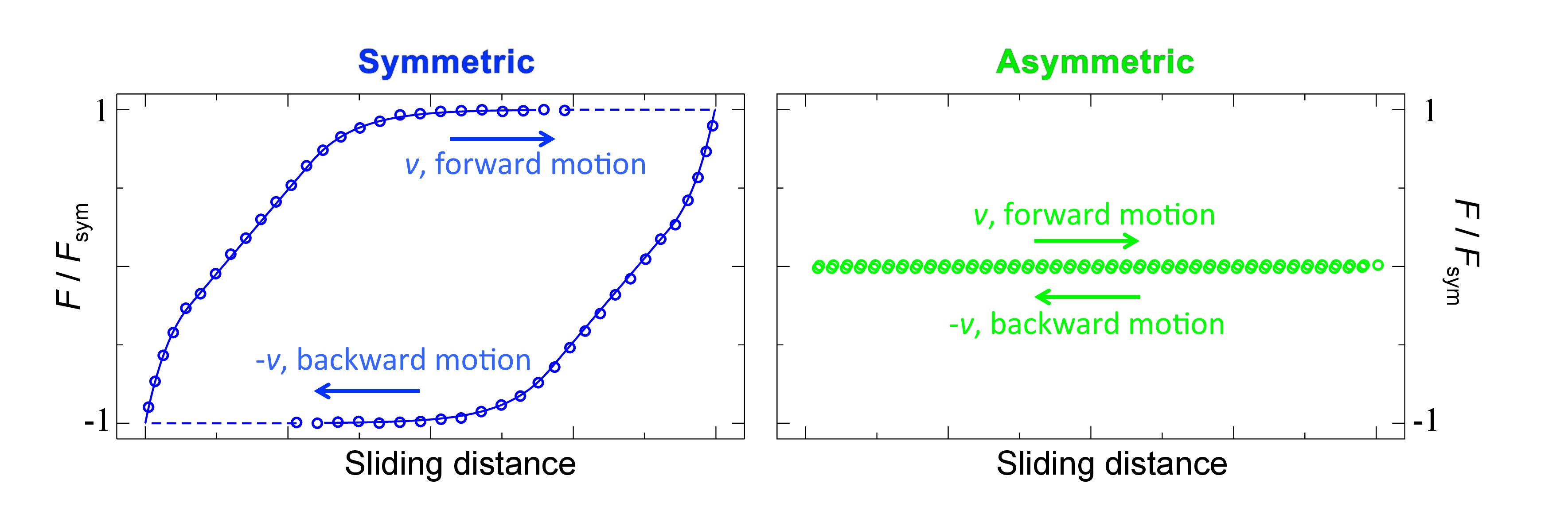
Figure 4. Averaged, filtered and smoothed force traces upon sliding the miscible (left) and immiscible (right) systems (adjusted from Ref. 22). The surface is moved back and forth by 40 μm at a scan-rate of 1 Hz and normal load of 30 nN.
Discussion
The presented results show that the friction, for immiscible systems of individually solvated brushes, is strongly reduced compared to traditional miscible systems of two of the same solvated brushes. The preferred absorbance of the different solvents in the two brushes prevents the brushes from interdigitating and consequently a major source of wear and dissipation in polymer brush friction is eliminated. The presented method is therefore fundamentally different from sliding dry hydrophilic on hydrophobic brushes, where the friction will be determined by brush-specific interactions27. In fact, upon shearing PMMA on PNIPAM (collapsed height 166 nm) without solvents, we found that the friction was 50% higher compared to dry PMMA on PMMA (collapsed height 236 m).
As already pointed out shortly in the notes of the ‘Protocol’ section, there are a couple of crucial points that need to be kept in mind while performing these particular experiments: Firstly, acetophenone is a better solvent for PNIPAM than water. Thus, care should be taken that acetophenone does not enter the PNIPAM brush by wetting the PNIPAM brush with plenty of water. Since acetophenone and water do not mix, the acetophenone will now not enter the PNIPAM brush. That is why we did not immerse our system completely in acetophenone, but instead created an acetophenone capillary for the miscible system. Another reason for incomplete immersion is that complete immersion results in too strong hydrodynamics, such that we only measured the Stokes drag on the colloid and cantilever. Secondly, in AFM experiments the torsional and normal spring constants are coupled. Cantilevers with a low normal spring constant will also have a relatively low torsional spring constant and vice versa. This limits the lowest measurable friction coefficient to >10-3. Thus, in order to measure the full friction reduction, the friction for the miscible system needs to be high. This is achieved by using long high-density brushes and a relatively high shear velocity of typically 100 m/sec. Moreover, the capillary between the brushes also increases the friction forces. We measured the lowest friction coefficient, for an immiscible system22, of μ = 0.003 under an estimated normal stress of 200 kPa. Using the same experimental conditions, we found that μ = 0.15 for the miscible system.
Note that the experiments were performed in a controlled laboratory environment and that surfaces used in industry are not as ideal as used in the presented experiments. Most surfaces have a non-uniform roughness distribution28 and thus many asperities of different shapes and sizes. During the collision of two brush-bearing asperities, the friction is composed out of different dissipation channels29. Next to steady-state dissipation mechanisms, such as interdigitation and solvent flow, there will be hysteretic effects in the shape30 due to the slow relaxation time of the polymers and solvent. Besides, capillaries are formed and broken. In the traditionally used miscible brush systems, transient interdigitation31 amplifies shape- and capillary hysteresis. With the immiscible system presented here, transient interdigitation is eliminated too. Moreover, capillary hysteresis can be circumvented by application of two immiscible solvents. Therefore, also for the more common rough surfaces, friction and wear will be reduced using immiscible brush systems22. The main source of friction that remains is brush deformation. Anchoring polyzwitterionic polymers, which are known for their intrinsic low friction32, onto one of the surfaces can minimize the latter. In such systems the osmotic pressure of the solvent is high resulting in little brush deformation under high normal loads.
The presented method of immiscible brush systems can be applied in almost any system where low friction is desirable. The method functions well under high pressures. However, care should be taken that the temperature is kept around RT. High temperatures damage the polymers, which will cause liquid-flow out of the contact and consequently high friction. Examples of potential application are: syringes, piston systems, axle bearings and hinges.
Disclosures
The authors have nothing to disclose.
Acknowledgements
We thank M. Hempenius and E. Benetti for fruitful discussions, Y. Yu for careful checking of the recipe, M. Vlot for the image design of Figure 1, C. Padberg and K. Smit for technical support. E.K. acknowledges the Netherlands Organization for Scientific Research (NWO, TOP Grant 700.56.322, Macromolecular Nanotechnology with Stimulus Responsive Polymers) for financial support. SdB has been supported by the Foundation for Fundamental research on Matter (FOM), which is financially supported by the Netherlands Organization for Scientific Research (NWO).
Materials
| Name | Company | Catalog Number | Comments |
|---|---|---|---|
| Methyl methacrylate | Sigma-Aldrich | M55909 | Monomer for PMMA synthesis, cleaned by pressing through a basic alumina column |
| (3-aminopropyl)triethoxysilane | Sigma-Aldrich | 440140 | vapor deposited silane monolayer |
| triethylamine | Sigma-Aldrich | T0886 | Reagent for the ATRP initiator moiety coupling. |
| 2-bromo-2-methylpropionyl | Sigma-Aldrich | 252271 | ATRP initiator moiety. |
| toluene | Biosolve | 20150501 | Coupling medium for ATRP moiety |
| CuBr | Sigma-Aldrich | 212865 | ATRP catalyst. |
| 2,2′-Bipyridyl | Sigma-Aldrich | 14453 | Cu complexing ligand for ATRP of MMA |
| N,N,N′,N",N"-Pentamethyldiethylenetriamine | Sigma-Aldrich | 369497 | Cu complexing ligand for ATRP of NIPAM |
| acetic acid 98-100% | Merck | 8187551000 | For cleaning CuBr. |
| Sulfuric acid | Sigma-Aldrich | 320501 | For the preparation of Piranha solution |
| Hydrogen peroxide 33% | Merck | 1.07210.1000 | For the preparation of Piranha solution |
| Ethanol | Merck | 1.00983.1000 | For cleaning substrates. |
| Basic aluminum oxide 60 | Merck | For cleaning monomers. | |
| Chloroform | Biosolve | 3080501 | For monolayer deposition and substrate cleaning. |
| Methanol | Biosolve | 13680501 | For polymerization medium. |
| Acetophenone | Acros Organics | 102410010 | For AFM measurement environment. |
| N-isopropyl acrylamide | Acros Organics | 412780250 | Monomer for PNIPAM synthesis, recrystallized from toluene/hexane |
| Poly(ethylene glycol) methacrylate | Sigma-Aldrich | 409529 | Monomer for Si-POEGMA synthesis, cleaned by pressing through a basic alumina column. |
| MilliQ water | MilliQ Advantage A 10 purification system | ATRP medium, AFM measurement environment and for substrate cleaning. | |
| Silicon substrates | |||
| Gold coated substrates | |||
| AFM probe, CP-FM-Au | SQube | AFM measurement | |
| [header] | |||
| dithiodiundecane-11,1-diybis[2-bromo-2-methlpropanoate] (DTPR) | Initiator, for Si-ATRP on gold surfaces. Synthesized according to Macromolecules, 33, 597-605 (2000). | ||
| Atomic Frorce Microscope | Bruker Multimode V controller |
References
- Lee, S., Spencer, N. D. Materials science - Sweet, hairy, soft, and slippery. Science. 319, 575-576 (2008).
- Milner, S. T., Witten, T. A., Cates, M. E. Theory of the Grafted Polymer Brush. Macromolecules. 21, 2610-2619 (1988).
- Klein, J., Kumacheva, E., Mahalu, D., Perahia, D., Fetters, L. J. Reduction of Frictional Forces between Solid-Surfaces Bearing Polymer Brushes. Nature. 370, 634-636 (1994).
- Raviv, U., et al. Lubrication by charged polymers. Nature. 425, 163-165 (2003).
- Moro, T., et al. Surface grafting of artificial joints with a biocompatible polymer for preventing periprosthetic osteolysis. Nat Mater. 3, 829-836 (2004).
- Bureau, L., Leger, L. Sliding friction at a rubber/brush interface. Langmuir. 20, 4523-4529 (2004).
- Muller, M. T., Yan, X. P., Lee, S. W., Perry, S. S., Spencer, N. D. Lubrication properties of a brushlike copolymer as a function of the amount of solvent absorbed within the brush. Macromolecules. 38, 5706-5713 (2005).
- Kobayashi, M., et al. Friction behavior of high-density poly(2-methacryloyloxyethyl phosphorylcholine) brush in aqueous media. Soft Matter. 3, 740-746 (2007).
- Zappone, B., Ruths, M., Greene, G. W., Jay, G. D., Israelachvili, J. N. Adsorption, lubrication, and wear of lubricin on model surfaces: Polymer brush-like behavior of a glycoprotein. Biophys J. 92, 1693-1708 (2007).
- Sui, X. F., Zapotoczny, S., Benetti, E. M., Schon, P., Vancso, G. J. Characterization and molecular engineering of surface-grafted polymer brushes across the length scales by atomic force microscopy. J Mater Chem. 20, 4981-4993 (2010).
- Li, A., et al. Covalently Cross-Linked Hydrogel Brushes with Tunable Interfacial and Bulk Properties. Macromolecules. 44, 5344-5351 (2011).
- Wang, N., et al. Nanomechanical and tribological characterization of the MPC phospholipid polymer photografted onto rough polyethylene implants. Colloid Surface B. 108, 285-294 (2013).
- Yoshizawa, H., Chen, Y. -L., Israelachvili, J. N. Fundemental mechanisms of interfacial friction. 1. Relation between adhesion and friction. J. Phys. Chem. 97, 4128-4140 (1993).
- Maeda, N., Chen, N. H., Tirrell, M., Israelachvili, J. N. Adhesion and friction mechanisms of polymer-on-polymer surfaces. Science. 297, 379-382 (2002).
- Klein, J. Shear, friction, and lubrication forces between polymer-bearing surfaces. Annu Rev Mater Sci. 26, 581-612 (1996).
- Leger, L., Raphael, E., Hervet, H. Surface-anchored polymer chains: Their role in adhesion and friction. Adv Polym Sci. 138, 185-225 (1999).
- Binder, K., Kreer, T., Milchev, A. Polymer brushes under flow and in other out-of-equilibrium conditions. Soft Matter. 7, 7159-7172 (2011).
- Galuschko, A., et al. Frictional Forces between Strongly Compressed, Nonentangled Polymer Brushes: Molecular Dynamics Simulations and Scaling Theory. Langmuir. 26, 6418-6429 (2010).
- Spirin, L., et al. Polymer-brush lubrication in the limit of strong compression. Eur Phys J E. 33, 307-311 (2010).
- Schorr, P. A., Kwan, T. C. B., Kilbey, S. M., Shaqfeh, E. S. G., Tirrell, M. Shear forces between tethered polymer chains as a function of compression, sliding velocity, and solvent quality. Macromolecules. 36, 389-398 (2003).
- Drummond, C. Electric-Field-Induced Friction Reduction and Control. Phys Rev Lett. 109, 154302(2012).
- Beer, S., Kutnyanszky, E., Schön, P. M., Vancso, G. J., Müser, M. H. Solvent-induced immiscibility of polymer brushes eliminates dissipation channels. Nat. Commun. 5, 3781(2014).
- Wong, T. S., et al. Bioinspired self-repairing slippery surfaces with pressure-stable omniphobicity. Nature. 477, 443-447 (2011).
- Matyjaszewski, K., Xia, J. H. Atom transfer radical polymerization. Chem Rev. 101, 2921-2990 (2001).
- Wagner, K., Cheng, P., Vezenov, D. Noncontact Method for Calibration of Lateral Forces in Scanning Force Microscopy. Langmuir. 27, 4635-4644 (2011).
- Green, C. P., et al. Normal and torsional spring constants of atomic force microscope cantilevers. Rev. Sci. Instrum. 75, 1988-1996 (2004).
- Vyas, M. K., Schneider, K., Nandan, B., Stamm, M. Switching of friction by binary polymer brushes. Soft Matter. 4, 1024-1032 (2008).
- Persson, B. N. J., Albohr, O., Tartaglino, U., Volokitin, A. I., Tosatti, E. On the nature of surface roughness with application to contact mechanics, sealing, rubber friction and adhesion. J Phys-Condens Mat. 17, R1-R62 (2005).
- Beer, S., Müser, M. H. Alternative dissipation mechanisms and the effect of the solvent in friction between polymer brushes on rough surfaces. Soft Matter. 9, 7234-7241 (2013).
- Persson, B. N. J. Theory of rubber friction and contact mechanics. J Chem Phys. 115, 3840-3861 (2001).
- Briels, W. J. Transient forces in flowing soft matter. Soft Matter. 5, 4401-4411 (2009).
- Chen, M., Briscoe, W. H., Armes, S. P., Klein, J. Lubrication at Physiological Pressures by Polyzwitterionic Brushes. Science. 323, 1698-1701 (2009).
Reprints and Permissions
