We present a procedure for highly controlled and wrinkle-free transfer of block copolymer thin films onto porous support substrates using a 3D-printed drain chamber. The drain chamber design is of general relevance to all procedures involving transfer of macromolecular films onto porous substrates, which is normally done by hand in an irreproducible fashion.
Method Article
Procedure for the Transfer of Polymer Films Onto Porous Substrates with Minimized Defects
* These authors contributed equally
In This Article
Summary
Abstract
The fabrication of devices containing thin film composite membranes necessitates the transfer of these films onto the surfaces of arbitrary support substrates. Accomplishing this transfer in a highly controlled, mechanized, and reproducible manner can eliminate the creation of macroscale defect structures (e.g., tears, cracks, and wrinkles) within the thin film that compromise device performance and the usable area per sample. Here, we describe a general protocol for the highly controlled and mechanized transfer of a polymeric thin film onto an arbitrary porous support substrate for eventual use as a water filtration membrane device. Specifically, we fabricate a block copolymer (BCP) thin film on top of a sacrificial, water-soluble poly(acrylic acid) (PAA) layer and silicon wafer substrate. We then utilize a custom-designed, 3D-printed transfer tool and drain chamber system to deposit, lift-off, and transfer the BCP thin film onto the center of a porous anodized aluminum oxide (AAO) support disc. The transferred BCP thin film is shown to be consistently placed onto the center of the support surface due to the guidance of the meniscus formed between the water and the 3D-printed plastic drain chamber. We also compare our mechanized transfer-processed thin films to those that have been transferred by hand with the use of tweezers. Optical inspection and image analysis of the transferred thin films from the mechanized process confirm that little-to-no macroscale inhomogeneities or plastic deformations are produced, as compared to the multitude of tears and wrinkles produced from manual transfer by hand. Our results suggest that the proposed strategy for thin film transfer can reduce defects when compared to other methods across many systems and applications.
Introduction
Thin film and nanomembrane-based devices have recently garnered wide interest due to their potential use in a broad range of applications, ranging from flexible photovoltaics and photonics, foldable displays, and wearable electronics1,2,3. A requirement for the fabrication of these various types of devices is the transfer of thin films to the surfaces of arbitrary substrates, which remains challenging due to the fragility of these films and the frequent production of macroscale defect structures, such as wrinkles, cracks, and tears, within the films after transfer4,5,6,7. Manual transfer by hand, tweezers, and wire loops are common methods of thin film transfer, but inevitably result in structural incongruities and plastic deformation8,9. Various types of thin film transfer methodologies have been explored such as: 1) polydimethylsiloxane (PDMS) stamp transfer, which involves the use of an elastomeric stamp to obtain the thin film from the donor substrate and subsequently transfer to the receiving substrate10, and 2) sacrificial layer transfer11, in which an etchant is used to selectively dissolve a sacrificial layer between the support substrate and the thin film, thereby lifting off the thin film. However, these techniques alone do not necessarily allow for thin film transfer without incurring damage to or defect formation within the thin films12.
Here, we present a novel, low-cost, and generalizable facile method based on sacrificial layer lift-off and meniscus-guided transfer within a custom-designed, 3D-printed drain chamber system, to mechanically place block copolymer (BCP) thin films onto the centers of porous substrates such as anodized aluminum oxide (AAO) discs with little-to-no incurred macroscale defect structures, such as wrinkles, tears, and cracks. In the present context, these transferred thin films can then be used as devices in water filtration studies, potentially after sequential infiltration synthesis (SIS) processing9. Image analysis of transferred films obtained from optical microscopy show that the meniscus-guided, drain-chamber system provides smooth, robust, and wrinkle-free samples. In addition, the images also demonstrate the system's ability to reliably place the thin film membranes onto the centers of the receiving substrates. Our results have significant implications for any type of device application requiring the transfer of thin film structures onto the surfaces of arbitrary porous substrates.
Protocol
1. Fabrication of the transfer tool and drain chamber system
- Attached (Supplementary Files 1, 2) is the engineering drawing for the drain chamber assembly consisting of two parts: top and bottom. Model this device according to the specifications of the desired system (e.g., the outer diameter of the receiving substrate) and export as an STL file for 3D printing.
- For the top part, utilize a filament printer of choice and print in the lowest resolution possible, including scaffolding wherever necessary. Adhere to the recommended parameters of the printer. It is also recommended that the top part be printed using poly(lactic acid) (PLA) to minimize material shedding.
- For the bottom part, use an inkjet resin printer or filament printer with a build height as fine as 20 µm.
NOTE: PLA is a suitable material which minimizes material shedding. - Scrub and clean both parts with deionized water, ensuring the removal of any potential shedding material from the printing process. Sonication in deionized water is also recommended. Test the threading on the two parts to ensure a good fit.
- Complete the drain chamber with a size 117 neoprene O-ring and tubing of the parameters specified in the supporting documents (Supplementary Files 1, 2). A schematic of the entire drain chamber assembly is shown in Figure 1.
- Print the transfer tool using any filament printer at medium to fine resolution. There are two parts: clamp and loading arm.
NOTE: It is highly recommended that the transfer tool be printed using poly(lactic acid) (PLA), as other plastics can be poorly wetted and cause the wafer to become wet unexpectedly. - Complete the clamp with a size 10 screw and then attach the clamp onto a laboratory jack.
2. Initial mechanized deposition and membrane lift-off from donor substrate
- Place a bare 25 mm-diameter AAO disc (or any arbitrary porous receiver substrate of choice) onto the bottom part of the drain chamber. Then, place the neoprene O-ring on top of the AAO disc and screw on the top part of the drain chamber.
- Rinse and/or sonicate the setup various times with deionized (DI) water. This helps to remove any dust and/or any remaining particulates from 3D printing.
- Place the piece of Si wafer with the transferable polymer stack (donor wafer) onto the lip of the transfer tool loading arm.
- Fill the drain chamber with 25 mL of DI water.
- Lower the laboratory jack so that the tool is dipped slowly into the entrance ramp of the drain chamber and that the donor silicon substrate is slowly submerged. Ensure that the wafer is submerged sufficiently for the membrane to completely delaminate and lift-off from the underlying donor substrate.
NOTE: Using a piece of Si wafer with no dust contamination will ensure easy separation from the donor substrate. - Slowly raise the transfer tool out of the water and move it out of the way, making sure not to disturb the floating membrane.
- Coax the membrane into the opening of the chamber with tweezers. Placing the tweezer in water in front of membrane will guide it due to surface tension. Touching the floating membrane itself is not necessary and should be avoided.
3. Meniscus-guided transfer to receiver substrate with the drain chamber system
- Connect tubing to the outlet of the bottom part of the drain chamber. Attach this tubing to a 20 mL Luer-lock syringe.
- Obtain a syringe pump with withdrawing functionality. Place the syringe onto the pump and withdraw water at a rate of 1-2.5 mL/min until all the water has been drained out.
- After 10 min, the water should be completely removed from the drain chamber. If there is still any residual water within the chamber, reconnect the syringe and tubing and continue to withdraw any residual water.
- After complete drainage of the water, the membrane will now be placed at the center of the receiver substrate. Disconnect the drain chamber from the syringe pump and disassemble the drain chamber to remove the receiver substrate containing the membrane.
NOTE: The total process including set-up takes ~15 min. Reducing the working volume of water and increasing the drain rate can shorten this process. - Allow the sample to dry completely at room temperature before further use in any application.
Results
The BCP membrane samples were fabricated according to the previously described procedure9. The samples were placed onto the lip of the loading arm of the 3D-printed transfer tool (Figure 1, left) and subsequently lowered, with a laboratory jack, onto the entrance ramp of the 3D-printed drain chamber tool (Figure 1, right). A sacrificial layer of poly(acrylic acid) (PAA) between the BCP membrane and underlying donor silicon substrate was dissolved in the water within the drain chamber, resulting in a floating BCP membrane. Then, the syringe pump (Figure 2, bottom) was operated to withdraw water at a volumetric flow rate of 2.5 mL/min, resulting in a total transfer time of 10 min (assuming an initial 25 mL of water within the drain chamber system). This method of thin film transfer was compared to manual thin film transfer by hand and tweezers, as displayed in Figure 3.
Representative images of BCP thin film samples manually transferred onto porous AAO substrates are shown in Figure 4. These images illustrate the poor quality of the manual transfer method, as evidenced by the severe plastic deformation and macroscale defect structures present in the BCP membranes. All of the BCP membranes have wrinkled and fragmented after manual transfer, in addition to the distortion of the initial rectangular geometry of the diced BCP membranes. The human error introduced by manual transfer results in incomplete transfer of the membranes, as well as lack of centering and/or accuracy of placement onto the receiver AAO substrate-this will be further examined with image analysis software.
Representative images of BCP thin film samples transferred onto porous AAO substrates, using meniscus guidance and the drain chamber system, are shown in Figure5. Upon inspection, these images show a marked difference from those in Figure 4, as each membrane's rectangular geometry has been preserved. There appears to be complete and uniform lamination of the membrane onto the receiver AAO substrates, without any large plastic deformation effects observed. Furthermore, there appears to be a high accuracy of centering of the BCP membrane onto the receiver substrates, which will be confirmed with image analysis software.
To characterize the accuracy of placement and centering of the BCP membrane on the receiver AAO substrate, centroid image analysis was conducted using ImageJ analysis software. Specifically, the distance between the centroid of the BCP membrane and the centroid of the receiver AAO substrate was calculated for each sample. These values are reported in Table 1 and Table 2, corresponding to the manual transfer method and the meniscus-guided/drain-chamber method, respectively. The center-to-center distances for manually transferred samples (Table1) varied widely, with values ranging from 0.533 mm to 8.455 mm. The average center-to-center distance and standard deviation for the samples transferred with the manual method was 3.840 mm 2.788 mm. In contrast, the center-to-center distances for meniscus-guided/drain chamber transferred samples (Table 2) showed much less variation, with values ranging from 0.282 mm to 0.985 mm. The average center-to-center distance and standard deviation for the meniscus-guided/drain chamber transferred samples was 0.521 mm 0.258 mm. These results suggest that the meniscus-guided/drain chamber transfer system provides greater accuracy and reproducibility with respect to placement and centering of the BCP membrane on the receiver substrate. When coupled with the limited plastic deformation and macroscale defect structures observed in these samples (Figure 4), as compared to those manually transferred (Figure 3), the meniscus-guided transfer with the use of the drain chamber system proves to be an effective and robust protocol for the transfer of thin film membranes to arbitrary porous substrates.
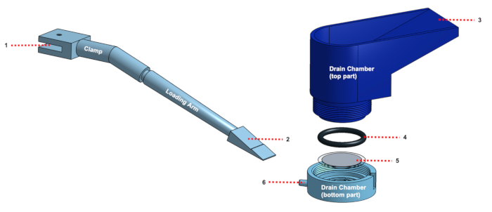
Figure 1: Schematic depicting the design and assembly of the transfer tool (left) and drain chamber (right). The transfer tool (left) consists of two individual parts: the clamp and the loading arm, as labeled. The clamp attaches to any standard laboratory jack at (1) with a size #10 screw. The donor substrate containing the to-be-transferred thin film membrane is placed at (2). The drain chamber (right) consists of two individual parts: the top part and the bottom part, as labeled. The donor substrate is lowered onto the entrance ramp at (3). A neoprene O-ring (4) is provided to ensure a tight seal between the receiver substrate (5) and the bottom part of the drain chamber. Water flows through the chamber and exits at the outlet (6). Please click here to view a larger version of this figure.

Figure 2: Complete experimental setup. (Top) Pictured shows the complete 3D-printed transfer tool (clamp and loading arm) and drain chamber system. (Bottom) Pictured is a syringe held by a syringe pump with withdrawing functionality, connected to the drain chamber system. The syringe pump withdraws water from the drain chamber system and allows for meniscus-guided transfer of the nanomembrane to the receiver substrate. Also pictured is a glass beaker covering the drain chamber system to prevent dust and other foreign particulates from entering the drain chamber system. Please click here to view a larger version of this figure.
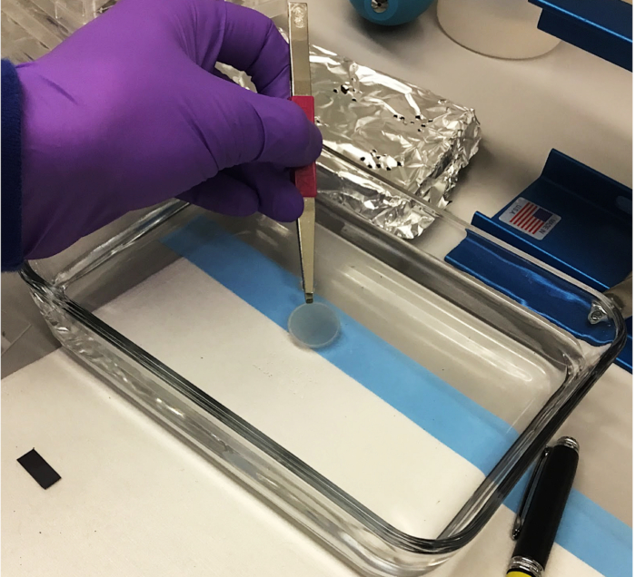
Figure 3: Manual thin film transfer method by hand and tweezers. In this method, the donor silicon substrate is slowly submerged into a bath of water, dissolving the sacrificial layer between the BCP membrane and substrate and releasing the BCP membrane into the bath. Subsequently, the user holds the receiver AAO substrate with a pair of tweezers and slowly "scoops" upward to place the BCP membrane onto the receiver AAO substrate. Please click here to view a larger version of this figure.
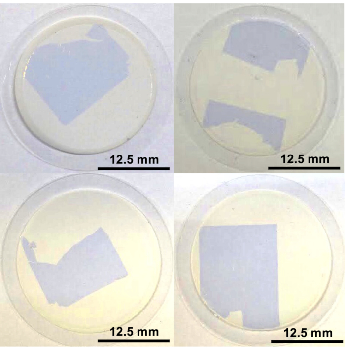
Figure 4: Optical images of manually transferred block copolymer (BCP) thin films. Photographs depicting the BCP membranes on top of the receiver AAO substrates (25 mm diameter), after manual transfer by hand and tweezers. Severe plastic deformation and macroscale defect structures are observed in the samples. Please click here to view a larger version of this figure.
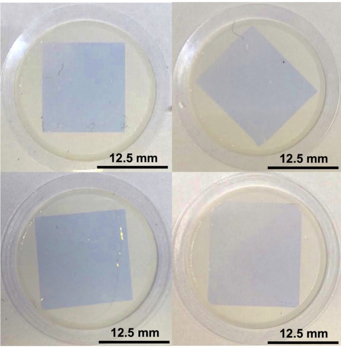
Figure 5: Optical images of meniscus-guided transferred block copolymer (BCP) thin films, specifically with the use of the 3D-printed transfer/drain chamber tool. Photographs depicting the BCP membranes on top of the receiver AAO substrates (25 mm diameter), after meniscus-guided/drain chamber transfer. Uniform lamination, with limited plastic deformation, is observed in the samples. Please click here to view a larger version of this figure.
| Sample | Center-to-Center Distance (mm) |
| 1 | 3.055 |
| 2 | 5.334 |
| 3 | 0.533 |
| 4 | 8.455 |
| 5 | 3.765 |
| 6 | 1.895 |
Table 1: Center-to-center distances for manually transferred samples. These values describe the distances between the center of the BCP membrane and the center of the receiver AAO substrate, determined by the centroid function of ImageJ analysis software. The center-to-center distance was 3.840 2.788 mm (mean ± SD).
| Sample | Center-to-Center Distance (mm) |
| 1 | 0.527 |
| 2 | 0.985 |
| 3 | 0.597 |
| 4 | 0.282 |
| 5 | 0.438 |
| 6 | 0.300 |
Table 2: Center-to-center distances for meniscus-guided/drain chamber transferred samples. These values describe the distances between the center of the BCP membrane and the center of the receiver AAO substrate, determined by the centroid function of ImageJ analysis software. The center-to-center distance was 0.521 0.258 mm (mean ± SD).
Discussion
While many of the steps listed in this protocol are crucial for the success of the thin film transfer, the nature of the custom-designed 3D printed drain chamber allows for broad flexibility, according to the user's specific requirements. For example, if the receiver substrate has a larger diameter than the 25-mm-diameter AAO discs utilized in this study, the drain chamber can be appropriately modified to fit the new specifications. However, there are certain aspects of the protocol that are necessary to ensure effective transfer results.
The choice of 3D-printed material for the transfer tool and drain chamber proves to be important for the success of this protocol. Both the transfer tool and drain chamber should be printed with materials that do not continually shed material, as pieces of debris from shedding can ruin the integrity of the thin film membrane. PLA and inkjet printable resin were both determined to be optimal materials for this purpose. When coupled with thorough cleaning with deionized water and sonication, the 3D-printed parts should not produce particulates that would otherwise contaminate the samples. Additionally, the choice of 3D-printed material for the transfer tool is critical to prevent damage from any water tension bubbles arising from initial contact between the loading arm and the water in the drain chamber. PLA was determined to be the optimal material in this respect, and other hydrophilic polymers should work as well. Therefore, we highly recommend that PLA be used for the transfer tool, whereas the drain chamber should be printed with PLA and/or inkjet printable resin.
Another critical aspect of the protocol is the guidance of the meniscus in the transfer process, as the meniscus helps place the membrane onto the center of the receiver substrate. This can be controlled by the choice of volumetric flow rate of the syringe pump. Too fast of a withdrawing rate (greater than 5 mL/min for this protocol) will likely damage the membrane and prevent the meniscus in slowly guiding the membrane to the center of the receiver substrate. 2.5 mL/min has been determined to be an optimal rate for this protocol, as it preserves structural integrity of the membrane and high accuracy of centering and placement onto the receiver substrate, without sacrificing efficiency. Likewise, these parameters can still be adjusted based on the specific considerations of the project, especially if the geometrical specifications of the 3D-printed drain chamber are changed.
While the described meniscus-guided/drain chamber transfer methodology helps to eliminate the creation of macroscale structural defects and severe plastic deformation in the transferred thin films, there is still the possibility of microscale defect structures within the membranes, such as fracturing and line/plane defects. However, these types of small-scale inhomogeneities might result from the initial fabrication of the samples rather than the transfer protocol itself. The role of such micro-scale defect structures on membrane performance is a topic of ongoing research.
We have demonstrated a simple methodology based on 3D-printing and meniscus guidance to accurately and reproducibly control the transfer of thin film BCP membranes from donor silicon substrates to porous substrates. Results from optical inspection and image analysis software confirm the resultant high quality of placement. This protocol could be extended to any research application that requires the accurate transfer and uniform lamination of thin films to arbitrary porous substrates.
Disclosures
The authors have nothing to disclose.
Acknowledgements
This work was supported as part of the Advanced Materials for Energy-Water Systems (AMEWS) Center, an Energy Frontier Research Center funded by the U.S. Department of Energy, Office of Science, Basic Energy Sciences. We gratefully acknowledge helpful discussions with Mark Stoykovich and Paul Nealey.
Materials
| Name | Company | Catalog Number | Comments |
|---|---|---|---|
| 35% sodium polyacrylic acid solution | Sigma Aldrich | 9003-01-4 | |
| Amicon Stirred Cell model 8010 10mL | Millipore | 5121 | |
| Anodized aluminum oxide, 0.2u thickness, 25mm diameter | Sigma Aldrich | WHA68096022 | |
| o ring neoprene 117 | Grainger | 1BUV7 | |
| Objet500 Connex3 3D Printer | Stratasys | ||
| Onshape 3D software | onshape | ||
| Polylactic acid filament | Ultimaker | ||
| ultimaker3 3d filament printer | Ultimaker | ||
| Vero Family printable materials | Stratasys |
References
- Shah, A., Torres, P., Tscharner, R., Wyrsch, N., Keppner, H. Photovoltaic technology: the case for thin-film solar cells. Science. 285 (5428), 692-698 (1999).
- Kim, T. H., et al. Full-colour quantum dot displays fabricated by transfer printing. Nat. Photon. 5 (3), 176(2011).
- Nomura, K., et al. Room-temperature fabrication of transparent flexible thin-film transistors using amorphous oxide semiconductors. Nature. 432 (7016), 488(2004).
- Pirkle, A., et al. The effect of chemical residues on the physical and electrical properties of chemical vapor deposited graphene transferred to SiO2. Applied Physics Letters. 99 (12), 122108-122110 (2011).
- Chae, S. J., et al. Synthesis of large-area graphene layers on poly-nickel substrate by chemical vapor deposition: wrinkle formation. Advanced Materials. 21 (22), 2328-2333 (2009).
- Zhu, W., et al. Structure and electronic transport in graphene wrinkles. Nano Letters. 12 (7), 3431-3436 (2012).
- Paronyan, T. M., Pigos, E. M., Chen, G., Harutyunyan, A. R. Formation of ripples in graphene as a result of interfacial instabilities. ACS Nano. 5 (12), 9619-9627 (2011).
- Stadermann, M., et al. Fabrication of large-area free-standing ultrathin polymer films. Journal of Visualized Experiments : JoVE. (100), e52832(2015).
- Zhou, C., et al. Fabrication of Nanoporous Alumina Ultrafiltration Membrane with Tunable Pore Size Using Block Copolymer Templates. Advanced Functional Materials. 27 (34), 1701756(2017).
- Meitl, M. A., et al. Transfer printing by kinetic control of adhesion to an elastomeric stamp. Nature Materials. 5 (1), 33(2006).
- Suk, J. W., et al. Transfer of CVD-grown monolayer graphene onto arbitrary substrates. ACS Nano. 5 (9), 6916-6924 (2011).
- Chen, Y., Gong, X. L., Gai, J. G. Progress and Challenges in Transfer of Large-Area Graphene Films. Advanced Science. 3 (8), 1500343(2016).
Reprints and Permissions
