Large laser-interferometers are being constructed to create a new type of astronomy based on gravitational waves. Their sensitivities, as for many other high-precision experiments, are approaching fundamental noise limits such as the atomic vibration of their components. We are pioneering technologies to overcome these limits using novel laser beam shapes.
Method Article
The Generation of Higher-order Laguerre-Gauss Optical Beams for High-precision Interferometry
In This Article
Summary
Abstract
Thermal noise in high-reflectivity mirrors is a major impediment for several types of high-precision interferometric experiments that aim to reach the standard quantum limit or to cool mechanical systems to their quantum ground state. This is for example the case of future gravitational wave observatories, whose sensitivity to gravitational wave signals is expected to be limited in the most sensitive frequency band, by atomic vibration of their mirror masses. One promising approach being pursued to overcome this limitation is to employ higher-order Laguerre-Gauss (LG) optical beams in place of the conventionally used fundamental mode. Owing to their more homogeneous light intensity distribution these beams average more effectively over the thermally driven fluctuations of the mirror surface, which in turn reduces the uncertainty in the mirror position sensed by the laser light.
We demonstrate a promising method to generate higher-order LG beams by shaping a fundamental Gaussian beam with the help of diffractive optical elements. We show that with conventional sensing and control techniques that are known for stabilizing fundamental laser beams, higher-order LG modes can be purified and stabilized just as well at a comparably high level. A set of diagnostic tools allows us to control and tailor the properties of generated LG beams. This enabled us to produce an LG beam with the highest purity reported to date. The demonstrated compatibility of higher-order LG modes with standard interferometry techniques and with the use of standard spherical optics makes them an ideal candidate for application in a future generation of high-precision interferometry.
Introduction
During the past decades high-precision interferometric experiments were pushed towards an ultimate sensitivity regime where quantum effects are starting to play a decisive role. In these ongoing and future experiments, such as laser cooling of mechanical oscillators 1, optical traps for mirrors 2, generation of entangled test masses 3, quantum non-demolition interferometry 4, frequency stabilization of lasers with rigid cavities 5, and gravitational wave detection 6, 7, 8, researchers are facing a multitude of limiting fundamental and technical noise sources. One of the most severe problems is the thermal noise of the cavity mirrors of the interferometric setups, which is caused by the thermal excitation of the atoms that make up the mirror substrates and the mirror reflective coatings 7, 8, 9. This effect, also called Brownian motion, will cause an uncertainty in the phase of the light reflected from any test masses and will therefore manifest as a fundamental noise limitation in the interferometer output. For instance, the projected design sensitivity of advanced gravitational wave antennae, such as Advanced LIGO, Advanced VIRGO, and the Einstein Telescope, is limited by this type of noise in the most sensitive region of the observation frequency band 10, 11, 12.
Experimental physicists in the community work hard in a continuous effort to minimize these noise contributions and to improve the sensitivity of their instruments. In the particular case of mirror Brownian noise, one method for mitigation is to employ a larger beam spot size of the currently used standard fundamental HG00 beam on the test mass surfaces, since a larger beam averages more effectively over the random motions of the surface 13, 14. The power spectral density of the mirror thermal noise has been shown to scale with the inverse of the Gaussian beam size for the mirror substrate and with the inverse square for the mirror surface 9. However, as the beam spots are made larger, a larger fraction of the light power is lost over the edge of the reflective surface. If one uses a beam with a more homogeneous radial intensity distribution than the commonly used HG00 beam (see for example Figure 1), the Brownian thermal noise level can be reduced without increasing this type of loss. Amongst all the more homogeneous beam types that have been suggested for new versions of high-precision interferometry, for example Mesa beams or conical modes 13, 14, the most promising are higher-order LG beams due to their potential compatibility with the currently used spherical mirror surfaces 15. For instance, the detection rate of binary neutron star in spiral systems - which are considered the most promising astrophysical sources for a first GW detection - could be enhanced by about a factor of 2 or more 16 at the cost of a minimal amount of modifications in the design of second-generation interferometers currently under construction 10, 11. In addition to the thermal noise benefits, the wider intensity distributions of higher-order LG beams (see as an example Figure 2) have been shown to mitigate the magnitude of thermal aberrations of optics within the interferometers. This would reduce the extent to which thermal compensation systems are relied upon in future experiments to reach design sensitivities 19.
We have investigated and successfully demonstrated the feasibility of generating LG beams at the levels of purity and stability required to successfully operate GW interferometers at the best of their sensitivity 16, 18, 19, 20, 21, 22. The proposed method combines techniques and expertise developed in diverse areas of physics and optics such as the generation of high stability, low noise single mode laser beams 23, the use of spatial light modulators and diffractive optical elements for the manipulation of the spatial profiles of light beams 18, 22, 24, 25, 26, and the use of advanced techniques for the sensing, control and stabilization of resonant optical cavities 27 aiming at a further purification and stabilization of the laser light. This method has been successfully demonstrated in the laboratory experiments, exported for tests in large-scale prototype interferometers 20, and for generating LG modes at high laser powers up to 80 W 21. In this article we present the details of the method of generating higher order LG beams and discuss a methodology for the characterization and validation of the resulting beam. Further, in Step 4 a method for numerical investigations of cavities with non-perfect mirrors 19 is outlined.
Protocol
Preamble: In this protocol section we assume that a pure, low noise, power-stabilized fundamental mode Gaussian beam is provided, for instance by means of the standard setup as shown in Figure 3 containing: a commercial Nd:YAG laser to generate continuous-wave infrared light at 1064 nm wavelength; a Faraday Isolator (FI) to avoid back-reflection of the light towards the laser source; and an Electro-Optic Modulator (EOM) to modulate the phase of the light. The resulting beam is injected into a triangular optical cavity, where the laser frequency and the light power are stabilized by means of active control loops 27, while the resonant cavity provides spatial filtering for unwanted beam shapes.
The setup described above and shown in Figure 3 is a conventional experimental arrangement that is used in scientific apparatuses demanding low noise laser stabilization for precision measurements 1-8. The protocol section below describes how this fundamental mode Gaussian beam can be efficiently converted into a higher order Laguerre-Gauss type optical beam with comparable performances, if not identical, in terms of purity, noise, and stability. This is implemented by means of the apparatus shown in Figure 4, whose design, construction, and operation is described in the sections below. In this example presented in this work the generated mode will be a LG33. However it is worth stressing that the technique has general validity and that the described protocol applies to any desired higher order LG mode.
1. Designing and Prototyping the Optical Mode Converter for Optimal Conversion of Fundamental Mode Laser Beam into Higher Order LG Beams
The requirement for a phase modulation profile to convert a fundamental mode beam into a higher-order LG beam is to replicate the phase cross-section of the desired LG mode, which will be imprinted via a proportional phase-shift onto the wavefront of the incident beam 26. Two types of mode-converters work in this way: Spatial Light Modulators (SLM) - computer-controlled liquid-crystal displays whose pixels can be controlled to imprint phase shifts on the incident light - and diffractive phase plates - etched glass substrates where the desired phase shifts are produced in transmission by the purposely varying thickness of the glass element. SLMs are flexible but lack stability and efficiency, while phase plates are stable and efficient, but lack flexibility. Therefore we advise the use of the SLM for initial studies and prototyping and the use of a phase plate for long-term operations.
Optimal conversion relies on the precise choice of the parameters (waist size and position) of the beam to be shaped. Therefore before injecting it onto a mode converter, the initial fundamental mode beam must be characterized, and its parameters re-shaped to match the ones offering optimal conversion - this operation is called 'mode-matching'.
- Pick up the beam from the fundamental mode setup described in Figure 3.
- Use a beam profiler equipped with real time image analysis software to measure the beam radius along the optical path. Once a sufficient set of radii has been acquired (generally at least 10 data points are needed for a good quality result), fit the measured radii and extract the beam waist size and its position.
- Establish the required radius for the beam at the conversion point. Use large beam sizes on the order of a few mm in order to use the full extent of the phase converter area.
- Select a set of lenses and their locations along the optical path that will re-shape the incoming beam parameters (waist size and position) into the desired ones. For alignment purposes it is convenient to place the mode converter at the waist of the incoming beam.
- Repeat steps 1.2 and 1.4 by means of successive adjustments of the lens positions until the desired beam parameters for mode conversion have been obtained.
- Position the SLM mode converter along the incoming beam path, and inject the beam onto the SLM. For a reflective type SLM we recommend using a small incident angle, of order 5 degrees or less. Large incident angle would cause astigmatism in the generated beam, breaking the LG mode cylindrical symmetry.
- Apply the phase profile to the SLM liquid crystal display - a phase cross-section of the desired higher order LG beam to be converted to. The phase modulation profile of the LG33 mode, which is currently investigated for application in future GW detectors 16, is shown in the example in Figure 5.
- Select the appropriate phase pattern size (the size of the beam corresponding to the phase pattern) based on the size of the injected beam. Table 1 contains a list of optimum beam size ratios for LG modes up to the order 9, derived using numerical simulations 28. Alternatively, find the optimal beam to image size ratio experimentally by varying the size of the phase pattern applied to the SLM and analyzing the images of the resulting beam.
- Observe the reflected beam from the SLM using a CCD camera at a distance of one or more Rayleigh ranges away from the SLM. Carefully align the SLM in order to optimize the symmetry of the beam image on the CCD.
During interaction with the phase modulating device, some of the injected light remains unmodulated due to the quantization of the phase modulation levels. This unconverted light propagates along the same axis of the converted beam, spoiling the desired phase modulation effects. To circumvent this problem one can overlay a blazed grating profile on the LG mode conversion phase image. The modulated light carrying the LG mode phase profile will be deflected by the blazed grating, whereas the unmodulated light, which does not interact with the substrate, will proceed undisturbed. This causes a spatial separation between the two types of beams.
- Overlap a blazing structure to the phase profile previously generated on the SLM. For LG modes with azimuthal index l>0, the phase pattern will have a 'forked grating' characteristic, as seen in the example in Figure 6.
- Optimize the blazing angle such that the diffraction angle into the first order is greater than the divergence angle of the beam. Proceed until a reasonable separation between higher diffraction orders is found (use a separation between the outer rings of the consecutive beams as large as the diameter of the outer rings themselves).
- Once an optimal conversion pattern is achieved, proceed to the manufacturing of the phase plate. These are commercially available and can be manufactured to meet a wide range of custom requirements. Use the results obtained during the optimization process with the SLM to define the optimal phase-conversion pattern to be etched onto the phase plate. Optional step: apply an anti-reflective coating on at least one of the surfaces of the phase plate to minimize scattering of the light back towards the laser source and dispersion of the light power.
2. Operation of the Phase Plate, Mode Conversion and Purity Enhancement
- Replace the Spatial Light Modulator with the phase plate. As for the SLM, it is convenient to position it at the waist of the injected fundamental mode beam to be converted.
- Carefully align the phase plate to the initial beam such that the phase plate is perpendicular to the beam and the beam is centered with respect to the phase structure.
- Propagate the beams transmitted through the phase plate until separation of the higher diffraction orders occurs. Beams can be easily visualized with a beam card.
- When a sufficiently 'good' separation is achieved (as described in step 1.12), obscure the higher diffraction order beams with an aperture centered on the main diffraction order.
The inability of the discussed phase plate designs to modulate amplitude as well as phase means that they will not convert all of the incoming fundamental beam into the desired mode. The result is a composite beam with a dominant desired LG beam over a background of other higher-order modes of minor intensity, as shown in Figure 7. In order to spatially filter out unwanted LG modes and enhance the mode purity, the converted beam can be injected into an optical resonant cavity. Such a cavity can operate as a 'mode selector' allowing only specific optical modes to be transmitted, depending on the cavity length relative to the light wavelength.
- Design the mode cleaner cavity. For the simplicity of its implementation, use a two-mirror linear cavity configuration, as shown in Figure 4, in which one of the mirrors is flat (usually the input mirror) and the other mirror (output) is concave. This provides optical stability and simplicity of implementation. A specific design that works well is one where the radius of curvature of the output mirror is 1 m and the distance between the mirror reflective surfaces is 21 cm 29. In this case, the optimal input beam radius is about 365 μm at the waist, located at the reflective surface of the flat mirror.
- Choose the cavity mirror reflectivities to determine the finesse of the cavity. Use a low finesse of order few hundreds to have a good suppression of unwanted mode orders without introducing large distortions due to coupling with degenerate modes (see Step 4). It is best to use mirrors with same reflectivity to maximize the cavity throughput.
- Use a rigid spacer as support for the two cavity mirrors to enhance immunity from mechanical vibrations. Glue the mirrors on the spacer, and interpose a piezoelectric ring element between one of the two mirrors and the spacer to allow for microscopic adjustments of the cavity length for longitudinal length control and stabilization purposes.
- Mode-match the beam generated by the phase plate to the mode cleaner cavity eigen-modes. Beam profiling of an LG beam cannot be performed using the same tools used for the fundamental mode beams, therefore record the intensity distribution of the beam with a CCD camera placed at different locations along the beam path and analyze the recorded images using custom-made fitting scripts that can identify the dominant desired LG mode and estimate the beam radius at the given position 30. An example of this beam intensity profile fitting procedure is shown in Figure 8.
- Once a sufficient set of beam diameters has been measured (generally, at least 10 data points are needed for a good quality result), fit the measured radii and extrapolate the beam waist diameter and its location. A good beam profile will look like the one shown in Figure 9. As in 1.2 and 1.4 select lenses and repeat the procedure described in 2.7, 2.8, and 2.9 until the optimal beam size and location are found. Once mode matching is achieved, inject the generated beam into the mode cleaner cavity, being sure that the reflecting surface of the input (flat) mirror is properly located at the waist of the injected beam.
- Optimize the alignment of the injected beam into the cavity, while scanning the cavity length by moving the mirror with the piezo, and monitor the transmitted beam.
- Use the measurements of the light transmitted by the mode cleaner cavity as a function of the cavity length (also called cavity scans) to investigate the mode content of the LG beam generated by the phase plate, and eventually assess the conversion efficiency of the phase plate itself.
- Identify the relevant parasitic modes via inspection of the CCD images. Evaluate the power of such modes via their amplitude in the photodiode signal and compute the exact mode content of the overall beam. The measured results and the exact mode content can be reproduced with and compared to numerical simulations 21. A good example of this analysis is given in Figure 10, and the mode-content results are presented in Table 2.
Once the optimal alignment of the beam into the mode cleaner cavity has been achieved, and the mode content of the injected beam has been analyzed, 'mode-cleaning' and enhancement of the purity of the composite LG beam can be finally implemented. A Pound-Drever-Hall locking scheme 27 can be used to stabilize the cavity length to the desired resonant mode. The light transmitted by the mode cleaner cavity can be read by a photodiode, which can provide the error signal necessary for the control loop that controls the cavity length.
- Lock the cavity length to the main resonance and record images of the profile of the resulting beam transmitted by the cavity with the CCD camera to diagnose the produced beam and qualify its purity.
3. Diagnostics and Characterization of the Generated LG Beam
In this experiment, two main properties define the quality of a 'good' beam for the successful implementation in high-precision interferometric measurements: the beam power and the beam purity. Other relevant properties such as the frequency or the power stability can be preserved making use of the same control techniques implemented on the fundamental mode beam, as described above.
- Measure the LG beam power by means of a laser power meter. Pay attention to beam clipping: an LG beam has a larger extension compared to a conventional Gaussian beam, and it may exceed the dimension of the sensitive area for most commercial instruments. Highest powers are obviously recommended.
- Assess the purity of the generated LG beam by comparison with a theoretical beam profile. To do this, take a picture of the beam intensity by means of the CCD camera profiler and estimate its beam radius, to derive the theoretical beam amplitude profile to compare the measured one with. Assess the purity via the squared inner product
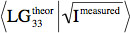 between the theoretical and the measured amplitude distributions. High purities are recommended.
Two important figures of merit are useful to evaluate the quality of the entire mode conversion process: the conversion efficiencies of the phase plate and of the overall setup.
- To evaluate the conversion efficiency of the phase plate, follow the cavity-scan procedure described at steps 2.11 and 2.12.
- Evaluate the conversion efficiency of the overall setup as the ratio between the power of generated desired LG beam vs the power of the injected fundamental mode Gaussian beam. High conversion efficiencies are obviously desirable.
4. Injection into Large Interferometers: Simulation Investigation
One application of this protocol is to investigate LG beams for their use in gravitational wave detectors. These are long baseline high precision interferometers. The baseline requires relatively large mirrors and beam sizes. This, however, enhances the effects of imperfect optics, especially when using higher order modes. This section describes a simulation based approach to investigate the behavior of higher order LG modes in realistic detectors.
- Select simulation tool to model light fields in an interferometer in order to test higher order LG modes. The simulation software should be able to model the effects of imperfections in the setup (misalignment, mode-mismatch, mirror figure error, etc.) on the mode content of the beam. An example is the simulation tool FINESSE 28.
- Set up a model of a real detector using the selected simulation tool. In the case of Advanced LIGO this is a dual recycled Michelson interferometer with Fabry-Perot arm cavities. The purpose of these initial simulations is to verify the reliability of the model, assuming perfect optics.
- Test the model with perfect fundamental mode beams. To validate the reliability of the model, this should allow for reproduction of a list of experimental procedures carried out in the real detector, such as: error signals and checks against expected numbers such as the power circulating in the arm cavities, cavity scans, and angular and longitudinal control of the interferometer and of its subsystems via sensing and control schemes. Further simulations should include the response of the interferometer to a gravitational wave signal. Once the simulations are performing as expected, the model can be adapted for higher order LG modes.
- Test the model with perfect LG33 beams: Adapt the interferometer design to the use of LG modes. This requires reducing the beam size on the cavity mirrors, which can be achieved by changing the radii of curvature of the mirrors. Once the model has been adapted for the LG mode, the tests carried out in 4.3 should be repeated with the new input beam. For the case of perfect optics the results should be very similar to those using HG00 (see for instance 19).
The use of higher order beams introduces a 'degeneracy' to the optical cavities as there are several different beam shapes fighting for dominance. An optical cavity resonant for a Gaussian mode is resonant for all modes of that order. An HG00 mode is the only mode of order 0, so all other modes are suppressed. For example, the LG33 mode is one of ten modes of order 9, all of which will be enhanced in the interferometer. Mirror surface distortions that are always present in real interferometers could couple the incident mode into other ones. If these new modes are of the same order as the incident beam they are enhanced in the arm cavities, resulting in highly distorted circulating beams. This can eventually deteriorate the instrument sensitivity.
- Setup a realistic interferometer model: Incorporate realistic data about the surface figures of the cavity mirrors. This data takes the form of a 'map' of the properties of the mirror surface, such as geometrical height or reflectivity, see an example for the Advanced LIGO mirrors in Figure 11. After including these effects, the performance of the higher order mode should be investigated, particularly in terms of the contrast defect at the detector output and the possibility of multiple zero crossings in error signals. In these areas, the higher order modes are expected to perform worse than HG00.
- Simulating subsystems: In order to better understand the degeneracy effects present in the model, simulate the subsystem in which the degeneracy originates, for instance the Fabry-Perot arm cavities in Advanced LIGO. Simulations of these subsystems should yield cavity scans and error signals to identify any frequency splitting and detection of the circulating field that can be analyzed in terms of its mode content.
- Mirror requirements: Derive more stringent requirements on the flatness of the mirror surfaces in the case that the results of Step 4.6 show an unacceptably high level of frequency-splitting or power in other modes which would make the implementation of higher order LG beams impossible. For this, analyze the direct inter-order coupling caused by such a surface which can be achieved numerically or using an analytic approximation 19. Use this method to identify any particular mirror shape that is causing large amounts of coupling between the input beam and modes of the same order. By comparing these results with the simulations, estimate the mirror requirements for these shapes, for a specific circulating beam purity. Finally simulate the full-scale interferometer model with mirror maps modified to the new specifications, illustrating the improvement in contrast defect and frequency splitting.
Results
All the experimental results so far described in the text and shown in the figures constitute a representative example of a successful execution of the beam conversion protocol. The most representative result is the purity of the generated beam: a successful beam conversion should lead to a beam purity on the order of 95% or above. A good example of successful beam conversion is the measurement of the intensity profile of an 82.8 Watts, 96% pure LG33 beam obtained in 21 and here shown in Figure 12.
Similarly, as discussed in protocol sections, the mode conversion efficiencies of the phase plate and of the overall experimental setup are a good indicator of the successful design of the experimental apparatus, including the phase plate and the mode cleaner cavity. Values of order 50% to 60% and above are generally considered a good value for the mode conversion efficiency. The highest conversion efficiency reported so far with this type of setup is about 70% 21.
The simulation investigation described in Protocol Sec 4 should result in numbers for beam purity with realistic mirrors, suggested mirror specifications and the resulting beam purity when these specifications are adopted. An example of the results you can expect with realistic mirror maps are shown in 19 where an original LG33 purity of 89% is obtained, compared to a purity of >99% for HG00. A purity of >99% for the LG33 mode is achieved using specific mirror requirements with a major reduction of astigmatism in the mirror surface.
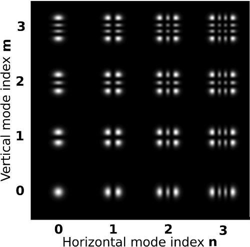
Figure 1. Intensity patterns for Hermite-Gauss (HG) modes up to order 6. The intensity patterns are normalized to have the same peak intensity, for visibility.

Figure 2. Intensity patterns for helical LG modes up to order 9. The intensity patterns are normalized to have the same peak intensity, for visibility.

Figure 3. Sketch of a conventional setup for production and stabilization of HG00 beams.
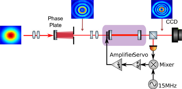
Figure 4. A sketch of the experimental setup discussed in this paper. The HG00 beam is first mode-matched to a desired waist size via a telescope then injected on the phase plate. The main diffracted beam is separated from the higher diffraction orders with an aperture and then sent to the Mode Cleaner cavity. A photodiode is used to extract the error signal for controlling the cavity length. The beam intensity is analyzed by a CCD camera.
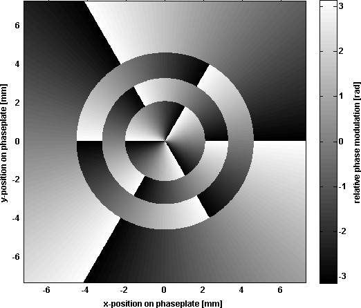
Figure 5. Phase modulation profile to convert a HG00 mode to LG33 mode.
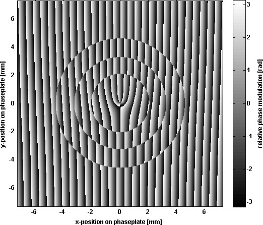
Figure 6. Example of blazed phase modulation profiles for generating LG33 modes.

Figure 7. Comparison between the intensity distribution of the composite beam generated by the phase plate (left) and the theoretical intensity distribution for a pure LG33 beam with same parameters.
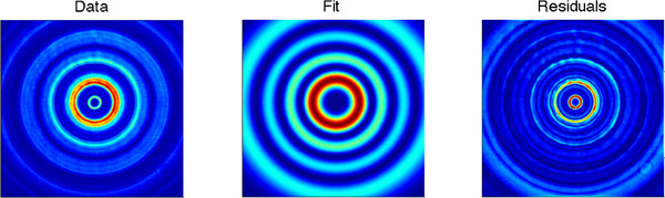
Figure 8. Example of beam intensity profile fitting applied to a real LG33 beam transmitted from a phase plate (left) compared to fit results (center) and residuals of fit (right). Click here to view larger figure.
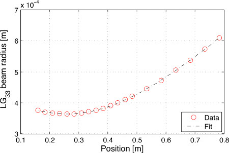
Figure 9. Profile of an LG33 beam with Gaussian fit shown for comparison.

Figure 10. Light power transmitted by a linear cavity as a function of the cavity length, when injecting a beam generated by the phase plate. The resonant peaks at 0 and 1 FSR correspond to the desired LG33 mode. A fit to this dominant mode is shown for comparison (blue line). The red curve shows the result of the numerical model, based on the modal content described in Table 2. Pictures of the unwanted beams to be filtered by the cavity are shown in the insets.
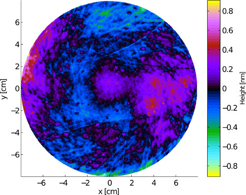
Figure 11. An example of a mirror surface map for one of the Advanced LIGO optical mirrors 19.
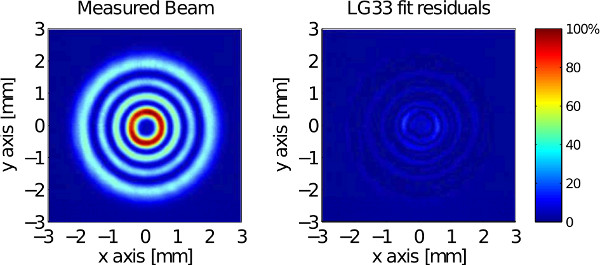
Figure 12. Intensity profile of a 82.8 W LG33 beam transmitted by a linear cavity (left) compared with fit residuals (right).
| p | l | 0 | 1 | 2 | 3 | 4 | 5 | 6 | 7 | 8 | 9 |
| 0 | 1.0 | 2.8 | 1.7 | 2.0 | 2.2 | 2.5 | 2.6 | 3.1 | 3.0 | 3.2 | |
| 1 | 1.7 | 2.7 | 2.2 | 2.4 | 2.6 | 2.8 | 2.9 | 2.8 | |||
| 2 | 2.2 | 2.4 | 2.5 | 2.7 | 2.9 | 3.0 | |||||
| 3 | 2.5 | 2.7 | 2.8 | 3.0 | |||||||
| 4 | 2.9 | 3.0 | |||||||||
Table 1. Optimum ratio between input HG00 beam size and LGpl phase image beam size for LG modes up to the order 9.
| Mode | LG33 | LG63 | LG43 | LG53 | LG32 | LG62 |
| Power | 75% | 8% | 4% | 4% | 4% | 1% |
Table 2. Mode content analysis described by the cavity scan shown in Figure 10.
Discussion
The output beams of most lasers used in high-precision measurements are designed to have a shape well described as a fundamental Gaussian mode. This particular beam geometry combines low diffraction with a spherical wave front. While the low diffraction is one of the key advantages of laser light, the spherical wave front is equally important, as it allows the low-loss transformation of the laser beam by standard optical components with spherical surfaces. Different beam shapes can be created as well, and recently Laguerre-Gauss beams have become of interest for their potential application in high-precision interferometry.
In this paper we demonstrated the experimental procedure to create higher-order Laguerre-Gauss modes with 95% purity for high-power, ultra stable laser beams. To achieve this, we have combined standard techniques from different aspects of optical research, namely diffractive phase plates and laser pre-stabilization to mode cleaner cavities. Our experiment provides a simple, modular and very reliable method to create high power beams in user defined higher-order modes. A commercial ultra-stable laser is used as the light source. Its output is injected to a diffractive phase plate, which can convert up to 75% of the light into the desired Laguerre-Gauss mode. This light is then injected to a small optical cavity and an electronic feedback loop is used to stabilize the laser frequency of the laser to the cavity length. The beam transmitted by the cavity is to 95% in the desired mode and, like the fundamental mode beam at the origin of the setup, has very good frequency stability at audio frequencies. All the parts represent standard components in modern optical experiments. We have successfully demonstrated this technique for laser powers up to 80 W pure Laguerre-Gauss 33 mode.
It could be possible to achieve similar results by replacing the phase plate with another mode-converting element (for example, other diffractive elements or astigmatic mode converters). Alternatively a laser could be setup with an optical resonator tuned for the desired Laguerre-Gauss modes, using for example, an amplitude mask. Finally the laser frequency stabilization to the reference optical cavity could be exchanged with a similar scheme that uses an atomic reference. The need for an electronic feedback system is probably the main disadvantage, but this is inevitable for any light source used for precision interferometer.
However, we believe that the method demonstrated in this paper provides a simple and modular scheme which can be scaled to all ranges of required laser frequency, power, or shape and thus presents a powerful and versatile method. Each part, the laser source, the diffractive element, as well as the optical cavity can be changed or optimized individually, which means that also existing laser injection systems can be upgraded to use Laguerre-Gauss modes.
Disclosures
Authors have nothing to disclose.
Acknowledgements
This work was funded by the Science and Technology Facilities Council (STFC).
Materials
| Name | Company | Catalog Number | Comments |
|---|---|---|---|
| The experimental apparatus discussed in this paper requires the following types of instruments: | |||
| Instrument | |||
| Solid state Laser source, Nd:YAG 1064 nm CW laser | Quantity: 1 | ||
| Faraday Isolator | Quantity: 1 | ||
| Electro-Optic Modulator (EOM) | Quantity: 1 | ||
| CCDcamera beam profiler | Quantity: 1 | ||
| Lenses | Quantity: depending on apparatus design | ||
| Steering Mirrors | Quantity: depending on apparatus design | ||
| Aperture | Quantity: 1 | ||
| High reflectivity mirrors (for normal incidence) | Quantity: 2 | ||
| Piezoelectric ring | Quantity: 1 | ||
| Cavity spacer | Quantity: 1 | ||
| Photodiodes and related control electronics | Quantity: 1 or more, depending on apparatus design | ||
| Spatial light modulator | Quantity: 1 Holoeye LCR-2500 | ||
| All the above instruments are commercially available and no particular specification is required. We leave the choice of the most suitable instruments to the experimenter’s discretion. | |||
| For the interest of the experimenter interested in reproducing the protocol, we recommend the following tools used in our experiment: | |||
| Tools | |||
| Innolight OEM 300NE, 1064 nm, 300 mW | Laser Source: | ||
| SIMTOOLs | Software for data analysis, available at www.gwoptics.org/simtools/ | ||
| FINESSE | Software for optical simulations, www.gwoptics.org/finesse/ | ||
| Finally, the phase plate employed in the present experiment was manufactured by Jenoptik GmbH, based on a custom design provided by the Authors. |
References
- Cohadon, P. F., Heidmann, A., Pinard, M. Cooling of a Mirror by Radiation Pressure. Physical Review Letters. 83, 3174-3177 (1999).
- Corbitt, T., et al. An All-Optical Trap for a Gram-Scale Mirror. Physical Review Letters. 98, 150802(2007).
- Müller-Ebhardt, H., Rehbein, H., Schnabel, R., Danzmann, K., Chen, Y. Entanglement of Macroscopic Test Masses and the Standard Quantum Limit in Laser Interferometry. Physical Review Letters. 100, 013601(2008).
- Kimble, H. J., Levin, Y., Matsko, A. B., Thorne, K. S., Vyatchanin, S. P. Conversion of conventional gravitational-wave interferometers into quantum nondemolition interferometers by modifying their input and output optics. Physical Review D. 65, 022002(2001).
- Numata, K., Kemery, A., Camp, J. Thermal-Noise Limit in the Frequency Stabilization of Lasers with Rigid Cavities. Physical Review Letters. 93, 250602(2004).
- Aufmuth,, Danzmann, K. Gravitational wave detectors. New Journal of Physics. 7, 202(2005).
- Harry, G. M., et al. Thermal noise in interferometric gravitational wave detectors due to dielectric optical coatings. Classical and Quantum Gravity. 19, 897-917 (2002).
- Crooks, D. R. M., et al. Excess mechanical loss associated with dielectric mirror coatings on test masses in interferometric gravitational wave detectors. Classical and Quantum Gravity. 19, 883-896 (2002).
- Yu, L. Internal thermal noise in the LIGO test masses: A direct approach. Physical Review D. 57, 659-663 (1998).
- Harry, G. M. the LIGO Collaboration. Advanced LIGO: the next generation of gravitational wave detectors. Classical and Quantum Gravity. 27, 084006(2010).
- Accadia, T., Acernese, F., Antonucci, F., Astone, P., Ballardin, G., Barone, F., et al. Status of the VIRGO project. Classical and Quantum Gravity. 28, 114002(2011).
- Sathyaprakash, B., Abernathy, M., Acernese, F., Ajith, P., Allen, B., Amaro-Seoane, P., et al. Scientific objectives of Einstein Telescope. Classical and Quantum Gravity. 29 (12), 124013(2012).
- Bondarescu, M., Thorne, K. S. New family of light beams and mirror shapes for future LIGO interferometers. Physical Review D. 74, 082003(2006).
- Bondarescu, M., Kogan, O., Chen, Y. Optimal light beams and mirror shapes for future LIGO interferometers. Physical Review D. 78, 082002(2008).
- Tournefier Mours, E., Vinet, J. Y. Thermal noise reduction in interferometric gravitational wave antennas: using high order TEM modes. Classical and Quantum Gravity. 23, 5777(2006).
- Chelkowski, S., Hild, S., Freise, A. Prospects of higher-order Laguerre-Gauss modes in future gravitational wave detectors. Physical Review D. 79, 122002(2009).
- Vinet, J. Y. Reducing thermal effects in mirrors of advanced gravitational wave interferometric detectors. Classical and Quantum Gravity. 24, 3897(2007).
- Fulda, P., Kokeyama, K., Chelkowski, S., Freise, A. Experimental demonstration of higher-order Laguerre-Gauss mode interferometry. Physical Review D. 82, 012002(2010).
- Bond, C., Fulda, P., Carbone, L., Kokeyama, K., Freise, A. Higher order Laguerre-Gauss mode degeneracy in realistic, high finesse cavities. Physical Review D. 84, 102002(2011).
- Sorazu, B., et al. Experimental test of higher-order Laguerre-Gauss modes in the 10 m Glasgow prototype interferometer. Class. Quantum Grav. 30, 035004(2013).
- Carbone, L., Bogan, C., Fulda, P., Freise, A., Willke, W. Generation of High-Purity Higher-Order Laguerre-Gauss Beams at High Laser Power. Physical Review Letters. 110, 251101(2013).
- Fulda, P., et al. Phaseplate design for Laguerre-Gauss mode conversion. , In Preparation (2013).
- Willke, B. Stabilized lasers for advanced gravitational wave detectors. Laser & Photonics Rev. , 1-15 (2010).
- Granata, M., Buy, C., Ward, R., Barsuglia, M. Higher-Order Laguerre-Gauss Mode Generation and Interferometry for Gravitational Wave Detectors. Physical Review Letters. 105, 231102(2010).
- Matsumoto, N., Ando, T., Inoue, T., Ohtake, Y., Fukuchi, N., Hara, T. Generation of high-quality higher-order Laguerre Gaussian beams using liquid-crystal-on-silicon spatial light modulators. J. Opt. Soc. Am. 25, 1642-1651 (2008).
- Kennedy, S. A., Szabo, M. J., Teslow, H., Porterfield, J. Z., Abraham, E. R. I. Creation of Laguerre-Gaussian laser modes using diffractive optics. Physical Review A. 66, 043801(2002).
- Black, E. D. An introduction to Pound-Drever-Hall laser frequency stabilization. American Journal of Physics. 69, 79-87 (2001).
- Freise, A., Heinzel, G., Lueck, H., Schilling, R., Willke, B., Danzmann, K. Frequency-domain interferometer simulation with higher-order spatial. Class.Quant.Grav. 21, (2004).
- Uehara, N. Mode cleaner for the Initial LIGO 10 Watt Laser. LIGO internal report. 12, (1997).
- Simtools, a collection of Matlab tools for optical simulations [Internet]. , Available from: http://www.gwoptics.org/simtools/ (2013).
Reprints and Permissions
