This article describes the preparation of well-ordered nickel nanofoams via electroless metal deposition onto nanoporous templates obtained from self-assembled diblock copolymer based supramolecules.
A subscription to JoVE is required to view this content. Sign in or start your free trial.
Method Article
Gyroid Nickel Nanostructures from Diblock Copolymer Supramolecules
In This Article
Summary
Abstract
Nanoporous metal foams possess a unique combination of properties - they are catalytically active, thermally and electrically conductive, and furthermore, have high porosity, high surface-to-volume and strength-to-weight ratio. Unfortunately, common approaches for preparation of metallic nanostructures render materials with highly disordered architecture, which might have an adverse effect on their mechanical properties. Block copolymers have the ability to self-assemble into ordered nanostructures and can be applied as templates for the preparation of well-ordered metal nanofoams. Here we describe the application of a block copolymer-based supramolecular complex - polystyrene-block-poly(4-vinylpyridine)(pentadecylphenol) PS-b-P4VP(PDP) - as a precursor for well-ordered nickel nanofoam. The supramolecular complexes exhibit a phase behavior similar to conventional block copolymers and can self-assemble into the bicontinuous gyroid morphology with two PS networks placed in a P4VP(PDP) matrix. PDP can be dissolved in ethanol leading to the formation of a porous structure that can be backfilled with metal. Using electroless plating technique, nickel can be inserted into the template's channels. Finally, the remaining polymer can be removed via pyrolysis from the polymer/inorganic nanohybrid resulting in nanoporous nickel foam with inverse gyroid morphology.
Introduction
There are several techniques available for the preparation of metal nanofoams: dealloying1-3, sol-gel approaches4,5, nanosmelting6,7, and combustion synthesis8. In the dealloying process, the starting material is usually a binary alloy, for example, an alloy of silver and gold. The less noble metal, silver in this case, can be removed either chemically or electrochemically resulting in a disordered porous gold foam with nanosized ligaments. In combustion synthesis, metal is mixed with an energetic precursor that releases energy during its decomposition and drives the formation of metal nanofoam8. Studies on the mechanical behavior of metal foams indicate that in disordered architectures stresses cannot be transmitted effectively from the ligament nanoscale to the overall macroscale9-11. Thus well-ordered metal nanofoams are expected to have superior mechanical properties in comparison to the disordered ones.
The idea represented here is to employ block copolymers that self-assemble into ordered nanostructures as precursors to metal nanofoams. Depending on the composition of a block copolymer, the total number of monomer units and the extent of repulsion between the chemically connected blocks, various morphologies appear such as: spherical, cylindrical, lamellar, double gyroid, hexagonally perforated lamellar, and others12-14. Furthermore, polymer blocks can be degraded selectively leading to nanoporous materials15. The most common methods include: ozonolysis16-18, UV irradiation19, reactive ion etching20-22, and dissolution23-26. The generated porous structures can be backfilled with various inorganic materials. Metal oxides (e.g. SiO2, TiO2) are usually introduced via sol-gel method into the template's channels27-29. Electrochemical and electroless plating are commonly used to deposit metal into or onto templates30-33. Finally, the remaining polymer can be removed from the polymer/inorganic nanohybrid via pyrolysis2, dissolution34,35, UV degradation28,29, etc.
In our approach, we start from a supramolecular complex of polystyrene-block-poly(4-vinylpyridine) (PS-b-P4VP) diblock copolymer and amphiphilic pentadecylphenol (PDP) molecules. This complex is a result of the hydrogen bonding between PDP and pyridine rings (Figure 1a). The composition of the starting block copolymer and the amount of added PDP are chosen in such a way that the obtained system self-assembles in the bicontinuous double gyroid morphology with a PS network and a P4VP(PDP) matrix (Figure 1b). PDP molecules become selectively dissolved in ethanol and P4VP chains collapse onto the PS network (Figure 1c). Subsequently, using electroless plating method, nickel is deposited into the pores of the template (Figure 1d). After the removal of the remaining polymer via pyrolysis, a well-ordered gyroid nickel nanofoam is obtained (Figure 1e).
Access restricted. Please log in or start a trial to view this content.
Protocol
1. Preparation and Characterization of PS-b-P4VP(PDP) Complexes with Double Gyroid Morphology
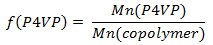
- Weigh out polystyrene-block-poly(4-vinylpyridine) (PS-b-P4VP) and pentadecylphenol (PDP, Mr = 304.51 g/mol). In order to obtain the gyroid morphology, carefully select the amount of PDP should be (the weight fraction of P4VP(PDP) block (fP4VP(PDP))should be ca. 0.6 according to the phase diagram of linear AB diblock copolymers). Usually, 0.15-0.2 g of a PS-b-P4VP leads to PS-b-P4VP(PDP) films 50-100 μm thick (given that the diameter of a Petri dish used in the step 1.3 is 5-6 cm). Calculate the amount of PDP according to the following equations:



- Dissolve PS-b-P4VP and PDP in chloroform and stir it for a couple of hours at room temperature. Maintain the concentration of polymer below 2 wt% to ensure the homogeneous complex formation.
- Pour the solution into a glass Petri dish.
- Place the dish into a saturated chloroform atmosphere.
- After about one week, take out the Petri dish. A film of the supramolecular complex is formed.
- Dry the film in vacuum at 30 °C overnight.
- Place the film in a specially designed container, remove the air from the container and then fill it with nitrogen. Anneal the film for 4 days in the oven at 120 °C under N2 atmosphere with 1 bar overpressure.
- Cut the small piece of the film, embed in epoxy and cure it overnight at 40 °C.
- Microtome the sample to a thickness of about 80 nm using a diamond knife at room temperature. The microtomed section will float on water. Pick them up and place on Cu grids.
- Put the grids containing the microtomed sections into a jar with iodine. After 45 min samples are stained and ready for transmission electron microscopy.
- Insert the Cu grids with stained sections in the transmission electron microscope operating at an accelerating voltage of 120 kV and image the sample.
- Insert the piece of the film (obtained after step 1.7) into the sample holder for small angle X-ray scattering and fix it with a Kapton tape. Place the prepared sample holder into the machine for SAXS. Open the X-ray shutter and acquire the 2D scattering pattern. Integrate the obtained 2D pattern and analyze the position of the peaks in 1D pattern.
2. Generation and Characterization of the Porous Structure
- Put the piece of the film (obtained after step 1.7) in ethanol and keep it for three days.
- Dry the sample.
- Prepare the samples for 1H NMR measurements. Dissolve PDP powder, PS-b-P4VP powder, supramolecular complex PS-b-P4VP(PDP) (after step 1.7), and porous film (after step 2.2) in CDCl3. Record 1H NMR spectra at room temperature.
- Analyze PS-b-P4VP powder, supramolecular complex PS-b-P4VP(PDP) (after step 1.7), and porous film (after step 2.2) by differential scanning calorimetry. Use a modulated mode with a heating/cooling rate of 1 °C/min, an oscillation amplitude of 0.5 °C, and an oscillation period of 60 sec. Equilibrate the samples at -30 °C, heat to 180 °C, cool to -30 °C, and then heat again to 180 °C. Use the data from the second heating cycle for the analysis.
- Outgas the porous sample (after step 2.2) for 8 hr at room temperature and for 18 hr at 70 °C and perform nitrogen adsorption measurements at 77 K.
- Use the appropriate software (for example, WinADP) and models to analyze the obtained isotherms.
- Dry the porous sample (after step 2.2) at 50 °C for 8 hr and degas it at room temperature and pressure of 0.5 Pa for 2 hr.
- Perform mercury porosimetry.
3. Inserting Nickel in the Polymer Template
- Weigh out tin chloride (SnCl2, Mr = 189.60 g/mol) and prepare an aqueous solution (0.1 M SnCl2 / 0.1 M HCl; 1.896 g SnCl2, 0.8 ml HCl, and 100 ml H2O). Put the solution on a shaker overnight to ensure the complete dissolution of SnCl2.
- Weigh out palladium chloride (PdCl2, Mr = 177.33 g/mol) and prepare an aqueous solution (0.0014 M PdCl2 / 0.25 M HCl; 0.025 g PdCl2, 2 ml HCl and 100 ml H2O).
- Prepare part 1 of the nickel plating bath: weigh out 6.78 g nickel sulfate hexahydrate (NiSO4•6H2O, Mr = 262.85 g/mol) and 2 g sodium citrate (Na3C6H5O7, Mr = 258.06 g/mol) and dissolve them in 80 ml of water. Add 828 μl 85% lactic acid (C3H6O3, Mr = 90.08 g/mol).
- Prepare part 2 of the nickel plating bath: weight out 0.2 g borane dimethylamine complex ((CH3)2NHBH3, Mr = 58.92 g/mol) and dissolve it in 20 ml of water. Borane dimethylamine complex should be handled in a well-ventilated fume hood.
- Immerse the porous film (after step 2.2) in the aqueous solution of tin chloride (step 3.1) for 1 hr.
- Rinse the film thoroughly with deionized water.
- Immerse the film in the aqueous solution of palladium chloride (step 3.2) for 1 hr.
- Rinse the film thoroughly with deionized water.
- Mix part 1 (3.3) and part 2 (3.4) of the nickel plating bath. Adjust the pH to 7.0 using ammonium hydroxide.
- Immerse the film in the nickel plating bath for 1 hr.
- Rinse the film thoroughly with deionized water.
- Dry the sample.
- Prepare the plated sample for electron microscopy as described in steps 1.8-1.9.
- Image the sample as described in step 1.11.
- Insert Cu grids containing the sections of the plated sample in the high-resolution transmission electron microscope. Acquire high-resolution TEM micrographs. Observe the sample under the microscope and choose the area for elemental analysis by EDX (Energy Dispersive Analysis of X-Rays). Perform the EDX analysis of the chosen area and analyze the obtained pattern.
4. Exposure of the Inverse Gyroid Nickel Foam
- Put the nickel-plated film (after step 3.12) in an oven at 350 °C and keep it from 1 hr up to 4 days.
- Attach the sample to the sample holder using a silver paste.
- Insert the sample into the scanning electron microscope. Acquire several images of the sample.
- Insert the sample into the scanning electron microscope. Observe the sample under the microscope and choose the area for elemental analysis by EDX. Perform the EDX analysis of the chosen area and analyze the obtained pattern.
Access restricted. Please log in or start a trial to view this content.
Results
The morphology of supramolecular complexes PS-b-P4VP(PDP)x is examined by TEM and SAXS. Figures 2a and 2b display typical gyroid patterns of a representative supramolecular complex: the double-wave and the wagon-wheel patterns that are known to represent projections through the (211) and the (111) plane of the gyroid unit cell, respectively. The PS block domains appear bright while the P4VP(PDP)x block domains appear dark due to iodine staining. Figure 2c repres...
Access restricted. Please log in or start a trial to view this content.
Discussion
Supramolecular complexes are successfully applied as precursors for well-ordered metal nanofoams. In this method, the crucial step is to acquire the appropriate template, i.e. a template with gyroid morphology. In the phase diagram of block copolymers the gyroid region is very small and it is rather difficult to target. This means that if conventional block copolymers are used as starting materials, the quite elaborate synthesis has to be repeated until the desired composition, that gives rise to the gyroid...
Access restricted. Please log in or start a trial to view this content.
Disclosures
The authors declare no competing financial interests.
Acknowledgements
We acknowledge financial support by the Zernike Institute for Advanced Materials, University of Groningen.
Access restricted. Please log in or start a trial to view this content.
Materials
| Name | Company | Catalog Number | Comments |
|---|---|---|---|
| Reagents | |||
| PS-b-P4VP, CAS: 26222-40-2 | Polymer Source Inc. | P9009-S4VP P136-S4VP P5462-S4VP P3912-S4VP | additional information are provided in a separate table |
| PDP | Aldrich | P4402-100G-A | recrystallized twice from petroleum ether |
| SnCl2 | Acros Organics | 196981000 | |
| PdCl2 | Aldrich | 76050 | |
| NiSO4•H2O | Sigma-Aldrich | 227676 | |
| Lactic acid | Aldrich | W261106 | |
| Citric acid trisodium salt | Sigma-Aldrich | C3674 | |
| Borane dimethyl amine complex | Aldrich | 180238 | |
| PS-b-P4VP catalogue number | Mn (PS), g/mol | Mn(P4VP), g/mol | PDI |
| P9009-S4VP | 24000 | 9500 | 1.1 |
| P136-S4VP | 31900 | 13200 | 1.08 |
| P5462-S4VP | 37500 | 16000 | 1.3 |
| P3912-S4VP | 41500 | 17500 | 1.07 |
References
- Erlebacher, J., Aziz, M. J., Karma, A., Dimitrov, N., Sieradzki, K. Evolution of nanoporosity in dealloying. Nature. 410, 450-453 (2001).
- Nyce, G. W., Hayes, J. R., Hamza, A. V., Satcher, J. H. Synthesis and Characterization of Hierarchical Porous Gold Materials. Chem. Mater. 19, 344-346 (2007).
- Detsi, E., van de Schootbrugge, M., Punzhin, S., Onck, P. R., De Hosson, J. T. M. On tuning the morphology of nanoporous gold. Scripta Mater. 64, 319-322 (2011).
- Gacoin, T., Lahlil, K., Larregaray, P., Boilot, J. P. Transformation of CdS Colloids: Sols, Gels, and Precipitates. J. Phys. Chem. B. 105, 10228-10235 (2001).
- Tappan, B. C., Steiner, S. A., Luther, E. P. Nanoporous Metal Foams. Angew. Chem. Int. Ed. 49, 4544-4565 (2010).
- Leventis, N., Chandrasekaran, N., Sadekar, A. G., Sotiriou-Leventis, C., Lu, H. One-Pot Synthesis of Interpenetrating Inorganic/Organic. Networks of CuO/Resorcinol-Formaldehyde Aerogels: Nanostructured Energetic Materials. J. Am. Chem. Soc. 131, 4576-4577 (2009).
- Leventis, N., Chandrasekaran, N., Sotiriou-Leventis, C., Mumtaz, A. Smelting in the age of nano: iron aerogels. J. Mater. Chem. 19, 63-65 (2009).
- Tappan, B. C., et al. Ultralow-Density Nanostructured Metal Foams: Combustion Synthesis, Morphology, and Composition. J. Am. Chem. Soc. 128, 6589-6594 (2006).
- Ashby, M. F., et al. Metal Foams: a Design Guide. Butterworth-Heinemann. , (2000).
- Tekoglu, C. Size Effects in Cellular Solids. , University of Groningen. (2007).
- Amsterdam, E. Structural Performance and Failure Analysis of Aluminium Foams. , University of Groningen. (2008).
- Bates, F. S., Fredrickson, G. H. Block Copolymer Thermodynamics: Theory and Experiment. Annu. Rev. Phys. Chem. 41, 525-527 (1990).
- Hamley, I. W. The Physics of Block Copolymers. , Oxford University Press. (1998).
- Abetz, V., Simon, P. Advances in Polymer Science. , Springer. Berlin / Heidelberg. (2005).
- Hillmyer, M. A. Nanoporous Materials from Block Copolymer Precursors. Adv. Polym. Sci. 190, 137-181 (2005).
- Mansky, P., Harrison, C. K., Chaikin, P. M., Register, R. A., Yao, N. Nanolithographic templates from diblock copolymer thin films. Appl. Phys. Lett. 68, 2586-2588 (1996).
- Hashimoto, T., Tsutsumi, K., Funaki, Y. Nanoprocessing Based on Bicontinuous Microdomains of Block Copolymers: Nanochannels Coated with Metals. Langmuir. 13, 6869-6872 (1997).
- Chen, S. -Y., Huang, Y., Tsiang, R. C. -C. Ozonolysis efficiency of PS-b-PI block copolymers for forming nanoporous polystyrene. J. Polym. Sci. A Polym. Chem. 46, 1964-1973 (2008).
- Thurn-Albrecht, T., et al. Nanoscopic Templates from Oriented Block Copolymer Films. Adv. Mater. 12, 787-791 (2000).
- Park, M., Harrison, C., Chaikin, P. M., Register, R. A., Adamson, D. H. Block Copolymer Lithography: Periodic Arrays of ~1011 Holes in 1 Square Centimeter. Science. 276, 1401-1404 (1997).
- Cheng, J. Y., Ross, C. A., Thomas, E. L., Smith, H. I., Vancso, G. J. Fabrication of nanostructures with long-range order using block copolymer lithography. Appl. Phys. Lett. 81, 3657-3659 (2002).
- Voet, V. S. D., et al. Interface Segregating Fluoralkyl-Modified Polymers for High-Fidelity Block Copolymer Nanoimprint Lithography. J. Am. Chem. Soc. 133, 2812-2815 (2011).
- Zalusky, A. S., Olayo-Valles, R., Wolf, J. H., Hillmyer, M. A. Ordered Nanoporous Polymers from Polystyrene-Polylactide Block Copolymers. J. Am. Chem. Soc. 124, 12761-12773 (2002).
- Crossland, E. J. W., et al. A Bicontinuous Double Gyroid Hybrid Solar Cell. Nano Lett. 9, 2807-2812 (2008).
- Uehara, H., et al. Size-Selective Diffusion in Nanoporous but Flexible Membranes for Glucose Sensors. ACS Nano. 3, 924-932 (2009).
- Voet, V. S. D., et al. Poly(vinylidene fluoride)/nickel nanocomposites from semicrystalline block copolymer precursors. Nanoscale. 5, 184-192 (2013).
- Brinker, C. J., Scherer, J. W. Sol-Gel Science: The Physics and Chemistry of Sol-Gel Processing. , Academic Press. (1990).
- Hsueh, H. -Y., et al. Inorganic Gyroid with Exceptionally Low Refractive Index from Block Copolymer Templating. Nano Lett. 10, 4994-5000 (2010).
- Hsueh, H. -Y., Ho, R. -M. Bicontinuous Ceramics with High Surface Area from Block Copolymer Templates. Langmuir. 28, 8518-8529 (2012).
- Riedel, W. Electroless Nickel Plating. , (1991).
- Mallory, G. O., Hajdu, J. B. Electroless Plating: Fundamentals and Applications. American Electroplaters and Surface Finishers Society. , (1992).
- Djokić, S. S. Modern Aspects of Electrochemistry. , Springer US. (2002).
- Djokić, S. S., Cavallotti, P. L. Modern Aspects of Electrochemistry. , Springer. New York. (2010).
- Crossland, E. J. W., Ludwigs, S., Hillmyer, M. A., Steiner, U. Control of gyroid forming block copolymer templates: effects of an electric field and surface topography. Soft Matter. 6, 670-676 (2010).
- Hsueh, H. Y., et al. Nanoporous Gyroid Nickel from Block Copolymer Templates via Electroless Plating. Adv. Mater. 23, 3041-3046 (2011).
- Vukovic, I., et al. Supramolecular Route to Well-Ordered Metal Nanofoams. ACS Nano. 5, 6339-6348 (2011).
- Mao, H., Hillmyer, M. A. Macroscopic samples of polystyrene with ordered three-dimensional nanochannels. Soft Matter. 2, 57-59 (2006).
- Kobayashi, Y., Tadaki, Y., Nagao, D., Konno, M. Deposition of Gold Nanoparticles on Polystyrene Spheres by Electroless Metal Plating Technique. J. Phys. Conf. Ser. 61, 582-586 (2007).
- Finnefrock, A. C., Ulrich, R., Toombes, G. E., Gruner, S. M., Wiesner, U. The plumber's nightmare: a new morphology in block copolymer-ceramic nanocomposites and mesoporous aluminosilicates. J. Am. Chem. Soc. 125, 13084-13093 (2003).
- Tyler, C. A., Morse, D. C. Orthorhombic Fddd network in triblock and diblock copolymer melts. Phys. Rev. Lett. 94, 208-302 (2005).
- Ranjan, A., Morse, D. C. Landau theory of the orthorhombic Fddd phase. Phys. Rev. E. 74, 011803(2006).
- Kim, M. I., et al. Stability of the Fddd Phase in Diblock Copolymer Melts. Macromolecules. 41, 7667-7670 (2008).
Access restricted. Please log in or start a trial to view this content.
Reprints and Permissions
