
A subscription to JoVE is required to view this content. Sign in or start your free trial.
Research Article

One constraint of preclinical research in the field of bone repair is the lack of experimental control over the local mechanical environment within a healing bone lesion. We report the design and use of an external fixator for bone repair with the ability to change fixator stiffness in vivo.
The mechanical environment around the healing of broken bone is very important as it determines the way the fracture will heal. Over the past decade there has been great clinical interest in improving bone healing by altering the mechanical environment through the fixation stability around the lesion. One constraint of preclinical animal research in this area is the lack of experimental control over the local mechanical environment within a large segmental defect as well as osteotomies as they heal. In this paper we report on the design and use of an external fixator to study the healing of large segmental bone defects or osteotomies. This device not only allows for controlled axial stiffness on the bone lesion as it heals, but it also enables the change of stiffness during the healing process in vivo. The conducted experiments have shown that the fixators were able to maintain a 5 mm femoral defect gap in rats in vivo during unrestricted cage activity for at least 8 weeks. Likewise, we observed no distortion or infections, including pin infections during the entire healing period. These results demonstrate that our newly developed external fixator was able to achieve reproducible and standardized stabilization, and the alteration of the mechanical environment of in vivo rat large bone defects and various size osteotomies. This confirms that the external fixation device is well suited for preclinical research investigations using a rat model in the field of bone regeneration and repair.
A number of studies have improved our understanding of the biologic mechanisms involved in bone tissue repair1-6. The effects of mechanical conditions on bone repair such as axial, shear and interfragmentary movements (IFMs) have been studied extensively7-15. In the past several years, more and more studies started to emerge describing the influence of mechanical environment on bone healing using fracture, osteotomy and large segmental bone defect in vivo models. Therefore, reliable fixation methods are needed to get reproducible and reliable study outcomes.
The mechanical environment around the healing fracture is very important as it determines the way the fracture will heal. Thus, the choice of fixation device is very important and should be carefully selected depending on the study design, and other factors such as gap size and the type of fracture. The fixation device’s mechanical properties are even more important when studying the bony healing of large bone defects to establish a fixation that provides not only a constant gap size throughout the experiment period of full weight bearing, but also an ideal mechanical environment for the healing bone. External fixators are commonly used in fracture and large bone defect experimental healing models because they have an advantage over other fixation devices. The main advantage of external fixators are that they allow for the change of the mechanical environment at the defect site in vivo without a secondary intervention, which can be achieved by changing or adjusting the stability bar of the device during the course of the experiment as the bone healing progresses. Moreover, it permits the application of specific local mechanical stimulation to enhance the repair of bone, and also provides the potential to measure the stiffness of callus tissue in vivo. Nevertheless, the devices also have a few disadvantages that include: irritation of soft tissue, infections and pin breakage.
Unfortunately, such implants were not available “off the shelf” at the time of the implant development, and investigators were forced to custom design their own fixators for an intended use. Therefore, one constraint of research in this area was the lack of experimental control over the local mechanical environment within a large segmental defect as well as osteotomies as it heals. The mechanical characteristics of an external fixator are defined by, and can be modulated by, a large number of variables which include: the distance between the pins, pin diameter, pin material, the number of pins, fixator bar length, fixator bar number, fixator bar material, fixator bar thickness and the distance from the bone surface to the fixator bar (offset). Surprisingly, only a paucity of studies could be found that have investigated the mechanical contributions of the individual components of fixators or whole frame configurations used in rodent studies16,18,28. For example, one study’s results showed that one of the main contributing factors in determining the total stiffness of the fixation construct was dominated by the flexibility of the pins in relation to their offset, diameter and material properties28. The results from the aforementioned studies clearly suggest that knowing the mechanical environment provided by the fixation device is extremely important, and yet, in many cases is not investigated in detail. The present paper reports the design, specifications, and in vivo implantation of an external fixator that addresses this issue. This fixator also allows for the modulation of the mechanical environment as healing progresses, a property that enables the study of the mechano-sensitivity of different stages of the healing process in vivo. Additionally, as well as imposing a controlled and reproducible local mechanical environment, its accessibility also allows for the modulation of this environment at different stages of bone healing.
The fixator we designed was based upon external fixation, which is widely used for fracture fixation16-21 and large defect models in experimental animals22-27. The difference between our external fixator and the other existing designs reported in the literature is that their stability bar is secured with screws to have a tight grip with Kirschner wires (K-wires). This type of design requires screws to be retightened biweekly (sometimes even weekly) to make sure that the distance of the offset is maintained as the loading is applied through weight bearing to prevent the loosening of the stability bar. If such loosening occurs, it allows for unwanted additional loading conditions such as angular, transverse and torsional shear movements to the healing bone (based on personal experience, communication with researchers). Knowing this, an external fixator was designed as such that when the stiffness of the fixator needs to be changed, it would be achieved by removing connection elements attached to the main module where the mounting pins are imbedded. The in vivo pilot experiment was performed with the new external fixator prototype to make sure that it meets all proposed demands before it is manufactured in larger quantities.
The main aim for this paper is to present a new surgical method for an external fixator used for large bone defects and osteotomies in the rat with the ability to change stiffness in vivo during the healing process. This fixation method is applied in vivo on the femora of rats.
Animal care and experimental protocols were followed in accordance with NIH guidelines and approved by the Beth Israel Deaconess Medical Center Institutional Animal Care and Use Committee, Boston, MA. (Protocol Number: 098-2009)
1. Preparation of Surgical Materials and Instruments
2. Surgical Procedure and Application of the External Fixator
3. External Fixator Implantation Method Using Saw Guide
4. External Fixator Implantation Method Without the Saw Guide:
The application of the external fixator can be also performed without using the saw guide. The beginning steps of the external fixator implantation are the same up until the unit with the saw guide is clipped on the bone (step 3.1). If the saw guide is not used, it is very crucial to keep the fixator plate in the correct orientation during the entire application procedure. The femur needs to be externally rotated in the anterolateral direction.
5. Change of External Fixator Stiffness In vivo
Design specifications
Stabilization of the rat femur with the external fixation system enables the creation of osteotomies from 0.5 to 5 mm. The external fixator system is a locked external fixator made of polyether ether ketone (PEEK - [the main body]) and titanium-aluminium-niobium alloy (TAN - [the mounting pins]), which offers a simple, reproducible and adjustable design, and is available in four different stiffnesses: 10, 40, 70 and 100% (100% being the standard, most rigid fixator (Figure 7) . Depending on each investigator’s study requirements, whether they will have to do implant stiffness adjustment in vivo as the bone healing progresses, the external fixator plate comes either as one solid piece (Figure 8) or with two connection elements (Figure 9A) and two main modules (Figure 9B) secured with two interlocking screws (Figure 9C) that have to be assembled prior to surgery (Figure 10A-F). The connection elements are of different thickness, and hence stiffness, and were developed to achieve fixation stiffness equivalent to 10% (0.75 mm thick), 40% (1.70 mm thick), 70% (2.10 mm thick) and 100% (2.50 mm thick; Figure 7). The external fixator stiffness of 100% was calculated based upon the 200 g approximate body weight of a mature rat, and then multiplied by a factor of 4, to a mass equal of 800 g. This was done to make sure that after creating a 5 mm defect, the fixator is capable of withstanding the weight bearing of the animal, thereby maintaining alignment and preventing the dislocation of defect fragments. The remaining three fixator stiffnesses were decreased by 30% respectively from the highest (100%) to have a variety of stiffnesses for studies with various purposes.
Each main module has two holes where the Mounting Pins are inserted. The fixator stiffness can be changed while it is still attached to the living animal by changing the connection elements secured with special interlocking screws (Figure 9C) using 0.5 mm square wrench box (Figure 9H) attached to the hand drill (Figure 9K). TAN (Titanium alloy) was used to make for mounting pins (Figure 9D) to secure the stability bar to the femur (Figure 7). The fixator comes in four pieces and needs to be assembled prior to use if a stiffness change is intended for the study (Figure 10A-F), if not, a single solid pieced fixator should be used. The distance between the outer screws is 16 mm and the distance between the middle screws is 11 mm. All holes are predrilled using a 0.79 mm drill bit (Figure 9E). The screws are locked in corresponding holes in the main fixator frame, which is parallel to the bone surface and set at a distance of 6 mm from the bone (Figure 7).
A saw guide was developed to enable the creation of an accurate, reproducible, 5 mm segmental defect in the femur (Figure 9I); it also serves as a positioning guide for the installation of the external fixator. The main frame of the external fixator is clipped on to the saw guide, and then the whole system is clipped onto the bone as shown in Figure 2B,C. The 5 mm gap is generated with a 0.22 mm Gigli wire saw (Figure 9J). Both the saw guide and the Gigli wire saw can be autoclaved at 134 ºC. If a different sized osteotomy is intended for the study, a custom designed saw guide is available. Due to the miniature size of the external fixator, a special set of implantation instruments was designed and acquired; a customized 0.79 mm drill bit (Figure 9E), 1.00 mm counter sinker for the predrilling of the holes (Figure 9F), 0.7 mm square wrench box for application of the mounting pins attached to the hand drill (Figure 9G), 0.5 mm square wrench box for application of the interlocking screws (Figure 9H), hand drill (Figure 9K). An Accu Pen drill (Figure 9L) was also developed. The core diameter of each mounting pin is 0.02 mm bigger than the drill bit to guarantee proper fitting of the mounting pins into the bone. When used together with a self-cutting screw tip, this has been shown to prevent loosening due to bone surface resorption at the bone-screw interface29. The drill bit (Figure 9E) is operated by a miniature electrical Accu Pen drill that produces 2,500 rpm with a power of 500 mW (Figure 9L).
In vivo experiments
Radiological examination confirmed that fixators of all stiffnesses maintained a 1 mm (not shown) or a 5 mm femoral defect during the entire 8 weeks of the experiment (Figure 11). This was especially important for the 5mm critical size defects, where spontaneous healing does not occur. No distortion or infections, including pin infections, were observed and pin loosening was absent if the instructions of the application were followed30. A complication of using the external fixator was seen if the weight of the rat at the time of surgery has exceeded 250 g, and a smaller size plate was used. In some of those instances, the loading on the mounting pins increased to a critical level so that the pin pullouts were occurring on the distal side of the femur anywhere from one week to two weeks after the surgery (Figure 12). In addition to that, if a larger sized animal is used, the muscle tissue surrounding the femur is relatively thick, which creates skin tension in the vicinity of the implant after the skin closes. Due to swelling tension, when the skin starts to heal it creates an itching sensation to the animal making some of the rats bite the fixator. Since the fixator is created from PEEK material, which is basically high density plastic, on rare occasions, some rats were known to chew through it. Again, in order to avoid this, it is very important to select the recommended body weight for animal studies or switch to the larger version of external fixator.

Figure 1. Surgical preparation of the rat femur. (A) Rat positioned in the prone position. (B) Shows the direction of the incision on the femur. (C) Shows incision made in the skin to expose muscle. (D) Shows incision made through the muscle to expose femur. (E) Shows a small clamp positioned under the bone to pass Gigli wire. (F) Shows Gigli wire passed underneath of bone.
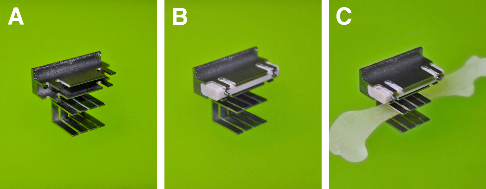
Figure 2. (A) Saw guide. (B) External fixator clipped on the Saw guide. (C) Saw guide with the external fixator clipped onto femur.

Figure 3. Application of external fixator. (A) Shows correct application of the first mounting pin with the plate reclining antero-laterally and parallel to the bone - green hand, and the incorrect application – red hand. (B) Shows insertion of the first Mounting Pin in the outer distal position. (C) Shows insertion of the remaining Mounting Pins starting with the most proximal position, followed by the two middle mounting pins. (D) Shows insertion of Mounting Pin – more detailed description in the protocol section 4.4.

Figure 4. Surgical implantation of the external fixator on the rat femur. (A) Demonstrates completion of the surgical procedure with external fixator in place with the Gigli wire. (B) Demonstrates created 5 mm segmental defect. (C) Demonstrates sutured muscle layer with exposed external fixator stability bar. (D) Demonstrates sutured skin with exposed external fixator stability bar.

Figure 5. (A) Initial position of Gigli wire for defect creation. (B) An image showing reciprocal motion of Gigli wire.

Figure 6. Change of External Fixator stiffness in vivo. (A) External fixator implanted on the femur. (B) Shows removal of the first interlocking screw by carefully turning it counter clockwise until the pin is half way out. (C) Shows removal of the second interlocking screw by carefully turning it counter clockwise until the pin is half way out. (D) Demonstrates removal of the connection element on the opposite side. (E) Demonstrates replacement of desired stiffness connection element in place of the removed one. (F) Demonstrates how to secure the first replaced connection element from the opposite side by turning the square box wrench until the interlocking screw is half way out of the opposite side. (G) Demonstrates how to secure the second replaced connection element from the opposite side by turning the square box wrench until the interlocking screw is half way out of the opposite side. (H, I) Demonstrates switching to the opposite side of the plate to make sure that both interlocking screws are half way out on the side where the connection element was replaced. (J) Demonstrates removal of the second connection element. (K) Demonstrates replacement of the second stiffness connection element in place of the removed one. (L, M) Demonstrates driving of both interlocking screws until the interlocking screw end exits the opposite side of the plate. (N) Demonstrates completed procedure.

Figure 7. Components of the external fixators. Left: Stiffness is determined by connection elements of different thicknesses. The fixator is attached to the bone with titanium alloy mounting pins. Right: Assembled fixator in place on rat femur with 5 mm segmental defect.

Figure 8. External fixator as a one unit.

Figure 9. Parts and instruments designed for use with the external fixator. (A) Two connection elements. (B) Two main modules. (C) Two interlocking screws. (D) Four mounting pins. (E) A 0.79 mm drill bit. (F) A 1.00 mm counter sinker for the predrilling of the holes. (G) A 0.7 mm square box wrench for the application of mounting pins. (H) A 0.5 mm square box wrench for the application of interlocking screws. (I) A 5 mm saw guide. (J) A 0.22 mm Gigli wire saw for creation of defect. (K) Hand drill for the attachment of drill bits, 0.70 and 0.50 mm square box wrench. (L) AccuPen 6V+ (Miniature electrical pen drill) used to drive the drill bits.

Figure 10. Assembly of the external fixator. (A) 70% stiffness connection element. (B) The connection element and one of the main modules. (C) demonstrates how one of the main modules slides inside of the connection element. (D) Demonstrates how both of the main modules slide inside of the connection element. (E) Demonstrates both of the main modules and both connection elements in place. (F) demonstrates fully assembled stability bar – main modules and connection elements secured with interlocking screws.
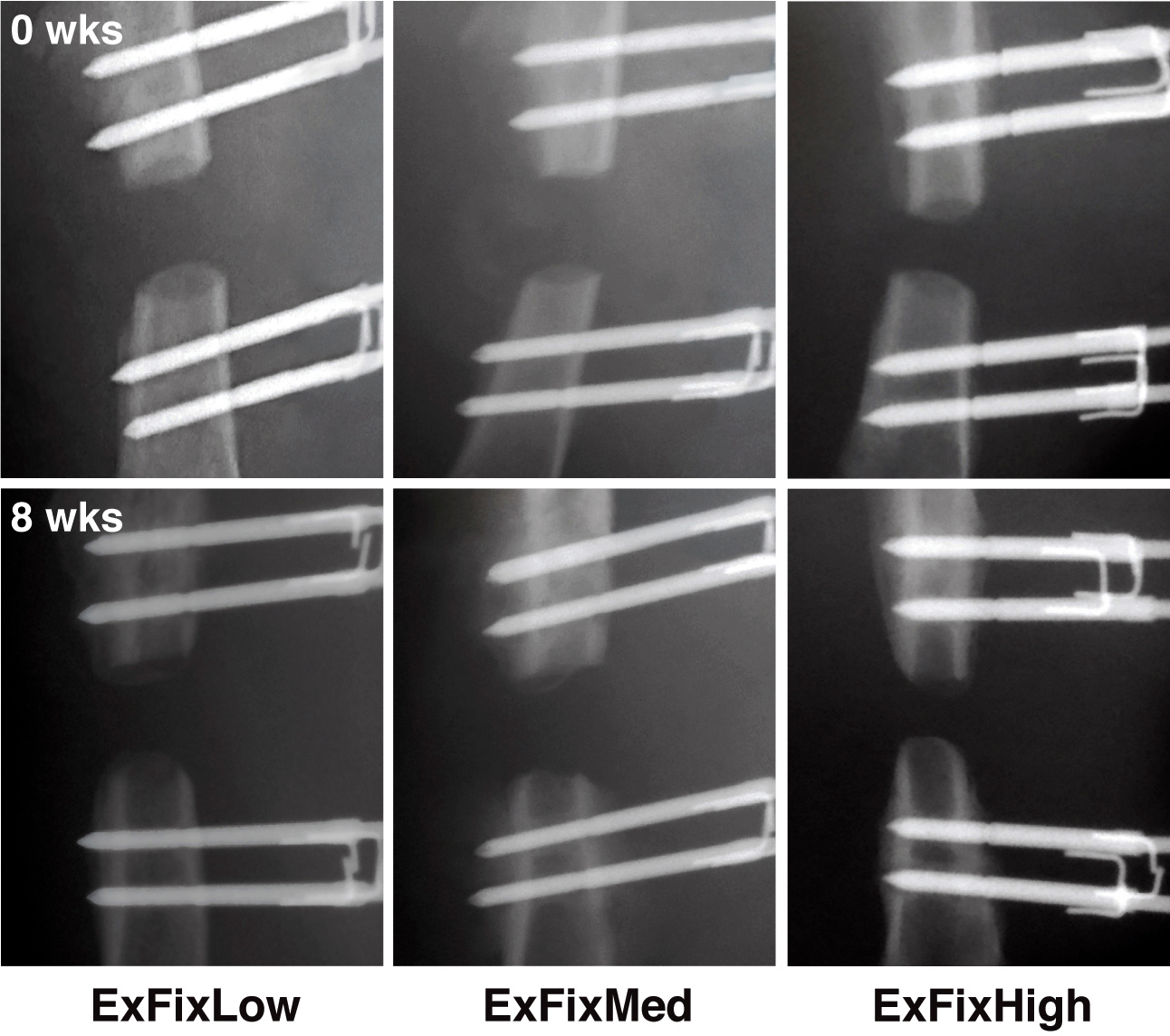
Figure 11. In vivo X-ray images of defects in rats immediately post-surgery and 8 weeks later. External fixators of all 3 stiffnesses were surgically implanted on rat femora and 5 mm segmental defects created. The defects were X-rayed immediately after surgery (t = 0) and at weekly intervals until 8 weeks (t = 8 weeks) when the experiment was terminated. Reproduced with kind permission from eCM journal (http://www.ecmjournal.org). Please click here to view a larger version of this figure.
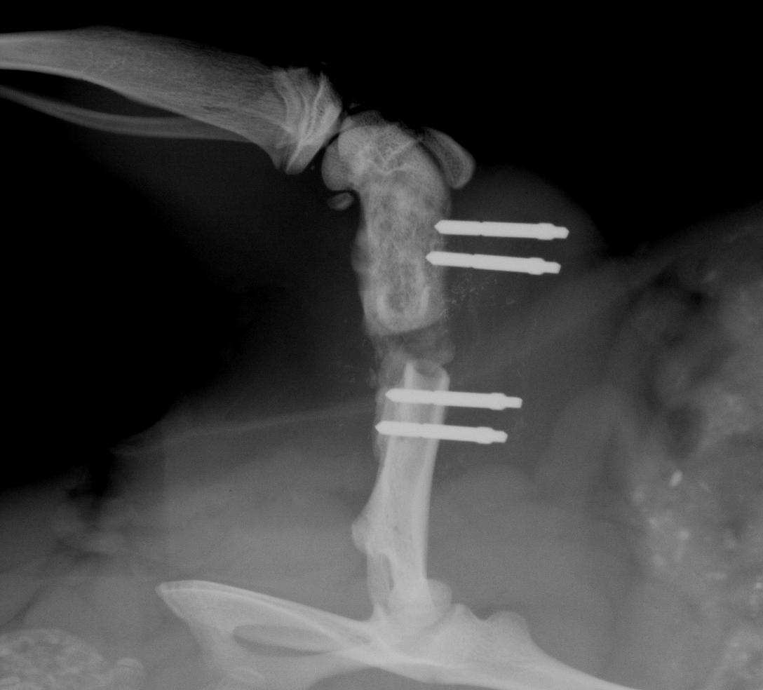
Figure 12. In vivo X-ray image of the defect in rat 9 days post-surgery with the distal pins pulled out (at the time of the surgery the body weight of the rat was 340 g). Please click here to view a larger version of this figure.
The most critical steps of a surgical procedure to create a large bone defect are: 1) choosing the appropriate body weight of the rat to match the size of the external fixator; 2) maintaining a sterile environment during the procedure; and 3) following the surgical procedure protocol.
The main goals of this study were to design, manufacture and characterize a new, variable stiffness external fixator for the rat femoral large defect model, and to use this fixator in determining the interplay between biological and mechanical factors during the healing process. The mechanical properties of the new fixators were examined at three levels and the characterization of the fixators is published in a different manuscript30. The fixators were also applied to rat femora and their in vivo performance monitored radiographically for 8 weeks with and without the treatment30,31.
The primary innovation of this fixator is its ability to exchange the stability bar connection elements to select different, standardized stiffnesses. Because the stability bar’s connection elements can be exchanged while the device is attached to the animal, the stiffness can be adjusted at different stages during the healing process. The connection elements are exchanged one at a time to prevent misalignment of the defect edges and the destruction of newly formed tissue as described in the protocol. Currently, four different stiffnesses are available, but additional stiffnesses can be achieved simply by ordering different connection elements of different thicknesses through the producer of the implant system.
The mounting pins and main frame were made from TAN and PEEK, respectively, because these materials are already used for orthopaedic implants in humans and their biocompatibility is well established. These materials also allow in vivo imaging in the early stages of fracture repair with minimal distortion, and a reduced incidence of infections. In vivo experiments confirmed that the fixators allowed clear imaging and maintained a 5 mm segmental gap for at least 8 weeks without infection or pin loosening.
As an additional design feature, the fixator has a pre-set offset of 6 mm from the bone surface to the stability bar no matter which stiffness connection elements are used. This feature makes implantation of the fixator very reproducible. Another major advantage over alternative designs described in the literature1,18,26,27, is that the new external fixator was designed to have a minimal mass (0.32 g) to avoid uncontrolled loading due to inertia. Furthermore, after the implantation and suturing of the skin, the clearance between the implant cross bar and the skin is only about 2 mm. Such close proximity to the skin surface minimizes the moment force, which prevents the possibility of an additional loading within the defect other than the one intended from the external fixator. In addition, to keep the surgical trauma low, conventional and rotating saws were not considered as tools for creating large or small osteotomies. Such saws either cut into adjacent tissue or strip the periosteum when the tissues are retracted. In the past we have used a 4.5 mm dental burr saw to create 5 mm defects and found that it was impossible to create exact and reproducibly sized defects with parallel ends22,26,27. To avoid all these problems we took an advantage of the Gigli wire saw of 0.22 mm. The saw guide was developed for reproducibly creating precise defects with parallel ends.
There are a few limitations when using this technique. One of the main concerns when using this external fixator is the possibility mentioned in the results section, that the rats might chew through the external fixator plate, which is made of PEEK. However, a special metal cover has recently been developed by the producer of the fixator to prevent this from happening. Likewise, an Elizabethan Collar can be used for the first couple of weeks after surgery to prevent the animal from chewing. An additional concern is that if an empty bone defect is used for the study, there is a chance that the mounting pins can pull out from the bone several weeks after the surgery. Furthermore, it is crucial that the fixator is implanted in the exact orientation that is outlined in the protocol. If the instructions are not carefully followed, there is a great risk that the mechanical environment provided by the specific stiffness fixator will not be as was intended, and will introduce an error, giving false results.
The fixators described in this paper enable investigators to undertake the experiments that are necessary to determine empirically the effects of various mechanical environments and/or mechanical (stiffness) modulation on bone healing in large defects or osteotomies30,31. Furthermore, the external fixator technology can be used in various studies where different pharmaceuticals and biomaterials are tested to discover new therapies not only for complex fractures, but also for the treatment of standard fractures in order to accelerate the healing process.
The author Romano Matthys is an employee of RISystem AG Davos, Switzerland that produces the implants, implant specific instruments & consumables used in this article. The author Vaida Glatt has no competing financial interests.
This work was supported by the AO foundation (S-08-42G) and RISystem AG.
We would like to extend a very big "thank you!" to Stephan Zeiter's team at the AO Research Institute Davos, Switzerland for being so accommodating in allowing us to use their OR facilities for the filming of this surgical procedure.
| RatExFix simple 100% | RISystem AG Davos, Switzerland | RIS.612.120 | |
| RatExFix simple 70% | RISystem AG Davos, Switzerland | RIS.612.123 | |
| RatExFix simple 40% | RISystem AG Davos, Switzerland | RIS.612.121 | |
| RatExFix simple 10% | RISystem AG Davos, Switzerland | RIS.612.122 | |
| RatExFix Connection element 100% | RISystem AG Davos, Switzerland | RIS.612.130 | |
| RatExFix Connection element 70% | RISystem AG Davos, Switzerland | RIS.612.131 | |
| RatExFix Connection element 40% | RISystem AG Davos, Switzerland | RIS.612.132 | |
| RatExFix Connection element 10% | RISystem AG Davos, Switzerland | RIS.612.133 | |
| RatExFix Main body | RISystem AG Davos, Switzerland | RIS.611.101 | |
| RatExFix InterlockingScrew | RISystem AG Davos, Switzerland | RIS.412.110 | |
| RatExFix Mounting pin 0.85 mm | RISystem AG Davos, Switzerland | RIS.412.100 | |
| RatExFix Saw Guide 100% 5 mm | RISystem AG Davos, Switzerland | RIS.312.100 | |
| Accu Pen 6V+ | RISystem AG Davos, Switzerland | RIS.390.211 | |
| HandDrill | RISystem AG Davos, Switzerland | RIS.390.130 | |
| Drill Bit 0.79 mm | RISystem AG Davos, Switzerland | RIS.593.203 | |
| Gigly wire saw 0.22 mm | RISystem AG Davos, Switzerland | RIS.590.100 | |
| Square box wrench 0.70 mm | RISystem AG Davos, Switzerland | RIS.590.112 | |
| Square box wrench 0.50 mm | RISystem AG Davos, Switzerland | RIS.590.111 | |
| Centering bit 1.00 mm | RISystem AG Davos, Switzerland | RIS.592.205 | |
| Scalpel Blade handle | Fine Science tools | ||
| Scalpel Blade (Size 15) | Fisher Scientific | ||
| Tissue Forceps | Fine Science tools | ||
| Scissors | Fine Science tools | ||
| Retractor | Fine Science tools | ||
| Needle Holder | Fine Science tools | ||
| Henahan Elevator | Fine Science tools | ||
| S-shape curved dissecting and ligature forceps | Fine Science tools | 2 | |
| Dressing Forceps | Fine Science tools | 2 | |
| Sterile Fenestrated drape | Fisher Scientific | for surgery | |
| Sterile gauze | Fisher Scientific | for surgery | |
| 5 ml syringe | Fisher Scientific | for irrigation of defect | |
| 24-27G needle | Fisher Scientific | for irrigation of defect | |
| 1 cc Insulin syringes | Fisher Scientific | for drug injections | |
| sterile saline | Fisher Scientific | for bone defect irrigation | |
| sterile gloves | Fisher Scientific | to perform surgeries | |
| chlorohezadine | Fisher Scientific | disinfecting solution for surgical site | |
| Vicryl suture 4-0 with SH-1 | Fisher Scientific | to suture muscle | |
| Ethibond suture 3-0 | Fisher Scientific | to suture skin | |
| Isofluorine | Sigma-Aldrich | for anesthesia | |
| Buprenorphine | Sigma-Aldrich | analgesia during and after the surgery | |
| Cefazolin | Sigma-Aldrich | antibiotic during and after the surgery | |
| Sprague-Dawley Rats or any other strain | Charles River Laboratories International, Inc. (Wilmington, MA USA) |


