

Summary
In the protocol, we present a method to manufacture a small caliber stent-graft by sandwiching a balloon expandable stent between two electrospun nanofibrous polyurethane layers.
Abstract
Stent-grafts are widely used for the treatment of various conditions such as aortic lesions, aneurysms, emboli due to coronary intervention procedures and perforations in vasculature. Such stent-grafts are manufactured by covering a stent with a polymer membrane. An ideal stent-graft should have a biocompatible stent covered by a porous, thromboresistant, and biocompatible polymer membrane which mimics the extracellular matrix thereby promoting injury site healing. The goal of this protocol is to manufacture a small caliber stent-graft by encapsulating a balloon expandable stent within two layers of electrospun polyurethane nanofibers. Electrospinning of polyurethane has been shown to assist in healing by mimicking native extracellular matrix, thereby promoting endothelialization. Electrospinning polyurethane nanofibers on a slowly rotating mandrel enabled us to precisely control the thickness of the nanofibrous membrane, which is essential to achieve a small caliber balloon expandable stent-graft. Mechanical validation by crimping and expansion of the stent-graft has shown that the nanofibrous polyurethane membrane is sufficiently flexible to crimp and expand while staying patent without showing any signs of tearing or delamination. Furthermore, stent-grafts fabricated using the methods described here are capable of being implanted using a coronary intervention procedure using standard size guide catheters.
Introduction
Coronary intervention procedures cause significant vessel wall injury due to disruption of the plaque and vessel wall. This results in restenosis, peripheral embolism in vein grafts, and discontinuity of coronary lumen1-4. To avoid these complications, a promising strategy will be to cover the vascular surface in the angioplasty site, which will potentially inhibit restenosis, mitigate risks from discontinuity of vessel lumen, and prevent peripheral embolism. Previous studies have compared bare metal stents to stent-grafts with positive outcomes for stent-grafts5. Researchers have used several materials to manufacture membranes to cover the stents. This includes synthetic materials like polyethylene tetraphthalate (PET), polytetrafluoroethylene (PTFE), polyurethane (PU), and silicon or autologous vessel tissue to manufacture covered stents6-9. An ideal graft material used to cover the stent should be thromboresistant, non-biodegradable, and should integrate with native tissue without excessive proliferation and inflammation10. The graft material used to cover the stent should also promote healing of the stent-graft.
Stent-grafts are widely used for the treatment of aortic coarctation, pseudo-aneurysms of the carotid artery, arteriovenous fistulae, degenerated vein grafts, and large to giant cerebral aneurysms. But the development of small caliber stent-grafts is limited by the ability to maintain low profile and flexibility, which aids in deployment of the stent-grafts11-14. PU is an elastomeric polymer with good mechanical strength which is a desired trait for achieving a low profile and good flexibility15,16. In addition to having good deliverability, stent-grafts should also promote rapid healing and endothelialization. PU covered stent-grafts have demonstrated better biocompatibility and enhanced endothelialization17. Researchers have previously tried to endothelialize PU covered stent-grafts by seeding them with endothelial cells17. Electrospinning of PU to create nanofiber matrix has been shown to be a valuable technique for the production of vascular grafts18,19. The existence of nanofibers that mimic the architecture of native extracellular matrix is also known to promote endothelial cell proliferation20,21. Electrospinning also allows for control over the thickness of the material22. Small caliber vascular grafts made of PU have been studied to promote healing by using modifications such as surface coatings, anti-coagulants, and cell proliferation suppressants. All these modifications are designed to mediate host acceptance and promote graft healing23.
Our group has developed a balloon expandable bare metal stent which can be deployed in animal models24-26. The combination of an electrospun polyurethane mesh and a balloon expandable stent has enabled us to generate small caliber balloon expandable stent-grafts. Most of the currently available stent-grafts are introduced through the femoral artery during an interventional procedure, but only a few commercial covered stents can be introduced 1 French size larger than that required for an un-inflated balloon27. In this study we have developed a small caliber vascular stent-graft by encapsulating a balloon expandable stent between two layers of electrospun PU which can be delivered to a coronary artery using a standard 8-9 French guide catheter in a percutaneous interventional procedure.
Subscription Required. Please recommend JoVE to your librarian.
Protocol
1. Electrospinning of Polyurethane on Mandrel Collector
- Prepare mandrel for electrospinning
- Melt approximately 8 ml of biocompatible, food-grade, water soluble support material in a graduated cylinder (approximately 9 mm diameter and 110 mm deep) at 155 °C using an oven.
- Dip a 3 mm diameter and 100 mm long stainless steel mandrel to obtain a coating of support material on the surface of the mandrel. Prior to dipping, place the mandrels in the oven at 155 °C for approximately 15 min to raise the temperature of the mandrel surface which helps in wetting the surface with the molten support material.
- Let the dipped mandrel cool to approximately 140 °C while the molten support material solidifies forming a uniform thin coating on the mandrel surface. During the cooling process, hang the mandrel vertically so that gravity causes excess support material to drip off. This coating enables easy removal of the finished stent-graft from the mandrel.
- Setup of the mandrel collector of the electrospinning system (as shown in Figure 1)
- Align the laboratory mixer horizontally and connect a plastic rod which will hold the stainless steel mandrel at the opposite end inside the fume hood.
- Dissolve the support material from the tip of the mandrel by submerging only the tip of the mandrel in water to accommodate the plastic support rod at the end of the mandrel. Support the plastic support rod at the free end of the mandrel to assist in uniform rotation of the mandrel collector.
- Use set screws in the plastic support rods to secure the stainless steel mandrel and avoid slipping during electrospinning.
- Ground the mandrel collector by attaching a U-shaped ground wire to the stainless steel mandrel. Use rubber O-rings to hold the ground wire to the sides of the mandrel.
- Setting up liquid polyurethane extrusion system of the electrospinning system
- Mix dimethylacetamide (DMA) with 25% (m/v) polyurethane (PU) stock solution to obtain 15% (m/v) PU in DMA solution (e.g., add 6 ml of DMA to 9 ml of 25% PU solution).
CAUTION! Work inside a fume hood with proper personal protective equipment. - Fill a 5 ml glass syringe with blunt end stainless steel needle (spinneret) with 15% PU solution.
- Program the syringe pump to extrude at 0.01 ml/min based on the inner diameter of the syringe.
- Mount the syringe with spinneret on the syringe pump horizontally with the needle tip approximately 20 cm from the mandrel collector. Insulate the syringe from the conductive parts of the syringe pump using rubber sheets to avoid electrical arcing.
- Connect the high voltage generator to the spinneret of the syringe using an alligator clip.
- Mix dimethylacetamide (DMA) with 25% (m/v) polyurethane (PU) stock solution to obtain 15% (m/v) PU in DMA solution (e.g., add 6 ml of DMA to 9 ml of 25% PU solution).
- Run the syringe pump at 0.01 ml/min and rotate the mandrel with the laboratory mixer running at slow speed (e.g., 50 rpm).
- Apply a voltage differential of 20 kV across the spinneret and the collector mandrel. PU nanofibers will start depositing on the rotating mandrel and a thin layer will be visible within several minutes. Ensure the fume hood is turned off and exhaust is closed to avoid loss of electrospun nanofibers.
2. Electrospinning a Stent-graft
- Electrospin PU nanofibers on a rotating mandrel for 2 hr to create a uniform tube (as explained in step 1).
- Remove the mandrel from the plastic rod connected to the laboratory mixer to install the bare metal stent. Turn on fume hood and open exhaust prior to removing the mandrel to ensure that remnant solvent fumes are removed.
- Slide the balloon expandable stainless steel stent26 onto the electrospun tube to a desired location. It may be necessary to slightly expand the stent so it slips on without damaging the electrospun tube.
- Crimp the stent to make sure that the stent is tightly set on the tube material on the mandrel and not loose enough to slide. This will also help to prevent delamination of the inner and outer layers.
- Load the mandrel with tube and stent again on the plastic rod of the laboratory mixer for electrospinning the outer layer of the stent-graft.
- Electrospin nanofibers for 3 hr as explained in step 1 to fabricate the outer layer of the stent-graft.
- After electrospinning the outer later, circumferentially cut the PU material approximately 1 mm from the ends of the stent using a scalpel.
- Soak the mandrel with stent-graft in deionized water to dissolve the support material from the mandrel which will release the stent-graft from mandrel. Replace with fresh water as needed to dissolve the support material completely.
- Once the support material is dissolved, gently remove the stent-graft from the mandrel and allow to dry. Consider soaking the removed stent-graft in deionized water to dissolve any remaining support material before allowing to air dry.
3. Testing of Manufactured Stent-grafts
- Slide the stent-graft on a 3 mm trifold balloon.
- Crimp the stent-graft onto the balloon using a hand held crimping tool.
- Inspect the crimped stent-graft using a microscope for uniform crimping and any other signs of failure like delamination or puncture of the cover material due to stent deformation.
- Expand the stent-graft to the designed diameter of 3 mm by pressurizing the trifold balloon with an inflation device and water. Again, examine the expanded stent-graft for uniform expansion and signs of failure.
Subscription Required. Please recommend JoVE to your librarian.
Representative Results
Our electrospinner setup (Figure 1) has resulted in high quality polyurethane nanofibers (Figure 2). A stent-graft is manufactured by electrospinning an inner layer of polyurethane onto a mandrel, slipping a bare metal stent over this layer, and electrospinning a second outer layer of polyurethane (Figure 3). Polyurethane nanofibers are electrospun at the rate of 50 µm/hr, which results in an inner layer of 100 µm and an outer layer of 150 µm on the stent-grafts. Electrospinning using the protocol presented here results in uniform nanofibrous polyurethane layers (Figure 4). Crimping and expansion of the resulting small caliber stent-graft showed that these devices are capable of being deployed using a standard trifold balloon without uneven crimping nor signs of material failure (Figure 5).
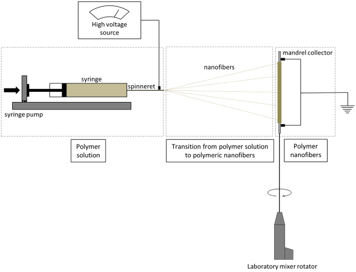
Figure 1. Schematic of electrospinning procedure. The nanofibers produced from the spinneret are collected on a rotating mandrel. Please click here to view a larger version of this figure.

Figure 2. Scanning electron microscopy (SEM) images of polyurethane nanofibers. SEM images of polyurethane nanofibrous material shows randomly orientated nanofibers at (a) 5,000X magnification and (b) 10,000X magnification. Please click here to view a larger version of this figure.
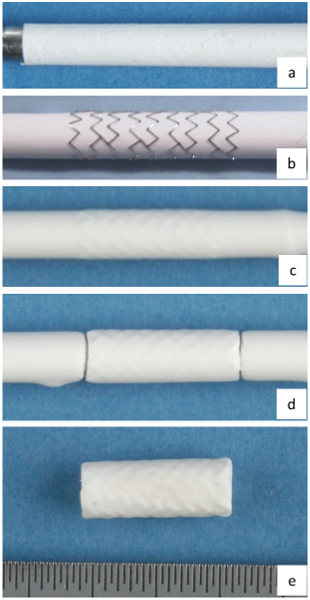
Figure 3. Steps in fabricating stent-grafts. (a) electrospun inner layer of stent-graft, (b) balloon expandable stent loaded on the electrospun layer, (c) electrospun outer layer of stent-graft, (d) stent-graft cut to length on mandrel, and (e) stent-graft with inner and outer layers on PU nanofibrous layers. Each division on the scale represents 0.5 mm. Please click here to view a larger version of this figure.

Figure 4. Microscopy images of electrospun polyurethane layers on a stainless steel mandrel. (a) mandrel without nanofibrous layer, (b) nanofibrous polyurethane layer on mandrel after 2 hours of electrospinning, and (c) nanofibrous polyurethane layer on mandrel after 5 hours of electrospinning. Inspection of polyurethane layers shows uniform thickness along the mandrel at various times of electrospinning. Each division on the scale represents 0.5 mm. Please click here to view a larger version of this figure.

Figure 5. Testing of stent-graft for crimping and expansion. (a) stent-graft crimped onto a 3 mm trifold balloon, (b) stent-graft expanded to designed diameter, and (c) stent-graft crimped and expanded. Each division on the scale represents 0.5 mm. Please click here to view a larger version of this figure.
Subscription Required. Please recommend JoVE to your librarian.
Discussion
We have developed a fabrication technique for a small caliber stent-graft which can be deployed using a standard percutaneous coronary intervention (PCI) procedure. Stent-grafts currently available are limited in their ability to maintain a low profile and flexibility for deployment. Bare metal stents developed by our group in our previous studies have proven to assist in rapid healing of the stented artery24,26. Various polymers have been electrospun by other groups and polyurethane has been proven biostable and biocompatible. Polyurethane is also known to have very little bacterial adherence13,28.
In the protocol presented in this study, we have developed a stent-graft with a balloon-expandable stent sandwiched between two layers of electrospun polyurethane and furthermore tested these stent-grafts for crimping and expansion. First, we have developed a stainless steel stent which is capable of crimping and expanding using standard PCI techniques. Second, we have developed an electrospinning technique which can generate good quality polyurethane nanofibers on a rotating mandrel collector. Finally, we have developed a process to sandwich the stent between two electrospun PU layers without delamination. The final device is capable of crimping and expansion on a standard 3 mm trifold balloon. We implanted 1-2 of these stent-grafts into 12 pigs (n=22 stent-grafts total) using standard 8 or 9 French guide catheters. The stent-grafts explanted after 7 days of implantation did not show any signs of mechanical failure nor occlusion of the blood vessel.
Stent-grafts are limited in use to large and medium caliber vessels and cannot be used in coronary vessels. Development of small caliber stent-grafts has been limited by the ability to control the thickness of the material covering the stent. Electrospinning of polyurethane provides the ability to precisely control the thickness of the material. The thickness of the electrospun polyurethane layer is time-dependent and the rate of accumulation is mainly affected by the distance between the spinneret and the collector mandrel, PU to DMA ratio, and the diameter of the collector mandrel. It should be noted that the length of a stent-graft presented in this protocol is 15 mm while the distance of the spinneret from the collecting mandrel is 200 mm. Hence, the ratio of stent-graft length to the distance is less than 0.1 which results in uniform electrospun nanofibrous layers. We used 15% (m/v) PU in DMA to obtain the desired uniform electrospun layers with high quality nanofibers. In the approach presented here, electrospun polyurethane nanofibers were deposited at the rate of 50 µm/hr on the rotating mandrel collector. The thickness of the inner layer was 100 µm while the thickness of the outer layer was 150 µm. Thicker nanofibrous material results in stiffer stent-grafts with a larger crimp profile, while thinner material results in puncturing during crimping and expansion. The resulting stent-grafts are prone to delamination, but this can be mitigated by crimping the stent on the inner layer prior to electrospinning the outer layer. It is also important to cut the electrospun material carefully, because cutting too close to the ends of the stent will cause the two layers to delaminate at the ends. Another critical step to achieve good quality stent-grafts is to uniformly coat the mandrel with water soluble, biocompatible support material. This helps in removing the stent-graft from the mandrel without disrupting the inner layer. This also helps to achieve a smooth inner surface of the stent-grafts.
Electrospun nanofibrous polyurethane covered stent-grafts are currently being used for treatment of aneurysms13. These stent-grafts are manufactured by sandwiching electrospun material between two stents which results in limited flexibility of the stent-grafts. The stent-graft developed in our study by sandwiching a balloon expandable stent between two electrospun layers has the advantage of using the flexibility of one stent while using the advantages of nanofibers for healing and mechanical strength. Nanofibrous material has the advantage of mimicking natural extracellular matrix which assists in healing of vascular grafts29. Stent-grafts developed in this study by combining electrospinning and balloon expandable stents have the potential to help in further development of rapidly healing small caliber stent-grafts.
Subscription Required. Please recommend JoVE to your librarian.
Disclosures
The authors declare that they have no competing financial interests.
Acknowledgments
We would like to thank the Division of Engineering, Mayo Clinic for their technical support. This study was financially supported by European Regional Development Fund - FNUSA-ICRC (No. CZ.1.05/1.100/02.0123), National Institutes of Health (T32 HL007111), American Heart Association Scientist Development Grant (AHA #06-35185N), and The Grainger Innovation Fund - Grainger Foundation.
Materials
| Name | Company | Catalog Number | Comments |
| Glass syringe | Air Tite | 7.140-33 | Syringe for spinneret |
| Graduated cylinder 5 ml | Fisher Scientific | 08-552-4G | 5 ml pyrex graduated cylinder about 9 mm diameter and 11 cm long |
| High voltage generator | Bertan Accociates, Inc. | 205A-30P | Used to apply voltage difference across spinneret and collector |
| Laboratory mixer with rpm control | Scilogex | SCI-84010201 | Available from various laboratory equipment suppliers |
| Polyurethane | DSM | BioSpan SPU | Biospan Segmented Polyurethane |
| Rubber sheet | McMaster Carr | 1370N11 | Used to insulate syringe during electrospinning |
| Stainless steel mandrel | N/A | N/A | Manufactured |
| Stainless steel needle | Hamilton | 91018 | Used as spinneret in electrospinning |
| Support material | EnvisionTec | B04-HT-DEMOMAT | Biocompatible water soluble material |
| Syringe Pump | Harvard Apparatus | 55-3333 |
References
- Elsner, M., et al. Coronary stent grafts covered by a polytetrafluoroethylene membrane. Am. J. Cardiol. 84 (3), 335-338 (1999).
- Störger, H., Haase, J. Polytetrafluoroethylene-Covered Stents: Indications, Advantages, and Limitations. J. Interv. Cardiol. 12 (6), 451-456 (1999).
- Moreno, P. R., et al. Macrophage infiltration predicts restenosis after coronary intervention in patients with unstable angina. Circulation. 94 (12), 3098-3102 (1996).
- Briguori, C., Sarais, C., Colombo, A. The polytetrafluoroethylene-covered stent: a device with multiple potential advantages. Int. J. Cardiovasc. Interv. 4 (3), 145-149 (2001).
- Qureshi, M. A., Martin, Z., Greenberg, R. K. Endovascular management of patients with Takayasu arteritis: stents versus stent grafts. Semin. Vasc. Surg. 24 (1), 44-52 (2011).
- Ahmadi, R., Schillinger, M., Maca, T., Minar, E. Femoropopliteal arteries: immediate and long-term results with a Dacron-covered stent-graft. Radiology. 223 (2), 345-350 (2002).
- Geremia, G., et al. Experimental arteriovenous fistulas: treatment with silicone-covered metallic stents. AJNR. Am. J. Neuroradiol. 18 (2), 271-277 (1997).
- Saatci, I., et al. Treatment of internal carotid artery aneurysms with a covered stent: experience in 24 patients with mid-term follow-up results. AJNR. Am. J. Neuroradiol. 25 (10), 1742-1749 (2004).
- Stefanadis, C., et al. Stents Wrapped in Autologous Vein: An Experimental Study1. J. Am. Coll. Cardiol. 28 (4), 1039-1046 (1996).
- Palmaz, J. C. Review of polymeric graft materials for endovascular applications. J. Vasc. Interv. Radiol. 9, 7-13 (1998).
- Bruckheimer, E., Dagan, T., Amir, G., Birk, E. Covered Cheatham-Platinum stents for serial dilation of severe native aortic coarctation. Catheter Cardiovasc. Interv. 74 (1), 117-123 (2009).
- Tzifa, A., et al. Covered Cheatham-platinum stents for aortic coarctation: early and intermediate-term results. J. Am. Coll. Cardiol. 47 (7), 1457-1463 (2006).
- Kuraishi, K., et al. Development of nanofiber-covered stents using electrospinning: in vitro and acute phase in vivo experiments. J. Biomed. Mater. Res. Part B Appl. Biomater. 88 (1), 230-239 (2009).
- Pant, S., Bressloff, N. W., Limbert, G. Geometry parameterization and multidisciplinary constrained optimization of coronary stents. Biomech. Model Mechanobiol. 11 (1-2), 61-82 (2012).
- Muller-Hulsbeck, S., et al. Experience on endothelial cell adhesion on vascular stents and stent-grafts: first in vitro results. Invest. Radiol. 37 (6), 314-320 (2002).
- Sarkar, S., Salacinski, H. J., Hamilton, G., Seifalian, A. M. The mechanical properties of infrainguinal vascular bypass grafts: their role in influencing patency. Eur. J. Vasc. Endovasc. Surg. 31 (6), 627-636 (2006).
- Shirota, T., Yasui, H., Shimokawa, H., Matsuda, T. Fabrication of endothelial progenitor cell (EPC)-seeded intravascular stent devices and in vitro endothelialization on hybrid vascular tissue. Biomaterials. 24 (13), 2295-2302 (2003).
- Grasl, C., et al. Electrospun polyurethane vascular grafts: in vitro mechanical behavior and endothelial adhesion molecule expression. J. Biomed. Mater. Res. A. 93 (2), 716-723 (2010).
- Kidoaki, S., Kwon, I. K., Matsuda, T. Structural features and mechanical properties of in situ-bonded meshes of segmented polyurethane electrospun from mixed solvents. J. Biomed. Mater. Res. Part B Appl. Biomater. 76 (1), 219-229 (2006).
- Stegemann, J. P., Kaszuba, S. N., Rowe, S. L. Review: advances in vascular tissue engineering using protein-based biomaterials. Tissue Eng. 13 (11), 2601-2613 (2007).
- Sankaran, K. K., Subramanian, A., Krishnan, U. M., Sethuraman, S. Nanoarchitecture of scaffolds and endothelial cells in engineering small diameter vascular grafts. Biotechnol. J. 10 (1), 96-108 (2015).
- Gibson, P., Schreuder-Gibson, H., Rivin, D. Transport properties of porous membranes based on electrospun nanofibers. Colloid Surf., A. 187, 469-481 (2001).
- Zdrahala, R. J. Small caliber vascular grafts. Part II: Polyurethanes revisited. J. Biomater. Appl. 11 (1), 37-61 (1996).
- Uthamaraj, S., et al. Design and validation of a novel ferromagnetic bare metal stent capable of capturing and retaining endothelial cells. Ann. Biomed. Eng. 42 (12), 2416-2424 (2014).
- Tefft, B. J., et al. Cell Labeling and Targeting with Superparamagnetic Iron Oxide Nanoparticles. J. Vis. Exp. (105), e53099 (2015).
- Uthamaraj, S., et al. Ferromagnetic Bare Metal Stent for Endothelial Cell Capture and Retention. J. Vis. Exp. (103), e53100 (2015).
- de Giovanni, J. V. Covered stents in the treatment of aortic coarctation. J. Interv. Cardiol. 14 (2), 187-190 (2001).
- Hans, F. J., et al. Treatment of wide-necked aneurysms with balloon-expandable polyurethane-covered stentgrafts: experience in an animal model. Acta. Neurochir. (Wien). 147 (8), 871-876 (2005).
- Hasan, A., et al. Electrospun scaffolds for tissue engineering of vascular grafts. Acta. Biomater. 10 (1), 11-25 (2014).
