This protocol describes the quantification of volumetric cerebral hemodynamic variations in the mouse brain using functional ultrasound (fUS). Procedures for 3D functional activation map following sensory stimulation as well as resting-state functional connectivity are provided as illustrative examples, in anesthetized and awake mice.
Method Article
Whole-Brain 3D Activation and Functional Connectivity Mapping in Mice using Transcranial Functional Ultrasound Imaging
* These authors contributed equally
In This Article
Summary
Abstract
Functional ultrasound (fUS) imaging is a novel brain imaging modality that relies on the high-sensitivity measure of the cerebral blood volume achieved by ultrafast doppler angiography. As brain perfusion is strongly linked to local neuronal activity, this technique allows the whole-brain 3D mapping of task-induced regional activation as well as resting-state functional connectivity, non-invasively, with unmatched spatio-temporal resolution and operational simplicity. In comparison with fMRI (functional magnetic resonance imaging), a main advantage of fUS imaging consists in enabling a complete compatibility with awake and behaving animal experiments. Moreover, fMRI brain mapping in mice, the most used preclinical model in Neuroscience, remains technically challenging due to the small size of the brain and the difficulty to maintain stable physiological conditions. Here we present a simple, reliable and robust protocol for whole-brain fUS imaging in anesthetized and awake mice using an off-the-shelf commercial fUS system with a motorized linear transducer, yielding significant cortical activation following sensory stimulation as well as reproducible 3D functional connectivity pattern for network identification.
Introduction
Over the last two decades, neuroimaging has become an important tool for studying brain function and organization, enabling researchers to make important discoveries in the field of neuroscience. Today, functional magnetic resonance imaging (fMRI) has become the gold standard clinical neuroimaging technique to assess task or drug-evoked brain activation and to map functional connectivity at rest. While human fMRI has high reliability and sensibility, mouse fMRI remains technically challenging for numerous reasons1. First, fMRI has a poor spatial and temporal resolution. The small size of the mouse brain necessitates the use of strong magnetic fields using expensive scanners to achieve reasonable spatial resolution. Second, maintaining stable physiological parameters within the narrow range allowing efficient neuro-vascular coupling is very difficult in anesthetized mice. Finally, the blood oxygen level dependent (BOLD) signal on which fMRI studies rely has relatively poor sensitivity, leading to low signal-to-noise ratio when applied to mice and often requires repeated stimulus presentation over long acquisition to detect small variations. The mouse being the most widely used animal model in biomedical preclinical research, these limitations are partly responsible for the translational gap in neuropsychiatry, hindering new promising therapeutic targets on the bench to be transposed into effective treatments on bedside.
Functional ultrasound (fUS) is a recently developed neuroimaging technique based on ultrafast doppler2. By directly sampling cerebral blood volume, this technique allows probing brain activity in real-time through the neurovascular coupling. Compared to other neuroimaging techniques, fUS yields a spatial resolution of 100 µm and a temporal resolution in the tens of milliseconds. This technique allows whole-brain imaging of complete coronal sections of the mouse brain, completely non-invasively. Furthermore, it is fully compatible with conscious and behaving animals3,4,5. One of the main current limitations of fUS is its 2D feature, allowing to record a single coronal plane at the same time. While volumetric 3D fUS using 2D matrix array transducers has already been successfully demonstrated in rats6 and confirmed in mice7, its current lack of sensitivity requires a full craniotomy as well as averaging an important number of trials to detect a slight change of activity. Alternatively, linear transducers can be stepped across multiple positions and perform functional imaging plane by plane to cover the whole brain. However, this technique requires numerous experimental paradigm repetitions and as such long acquisition times (3-4 hours for the mouse brain)8,9.
In the present work, we describe a robust experimental platform including a commercially available functional ultrasound scanner and a fast plane-switching linear transducer with procedures to acquire 3D fUS data in anesthetized and awake mice, allowing volumetric and transcranial functional mapping of the mouse brain, non-invasively, without contrast-agent and within short acquisition times. We illustrate this feature by mapping somatosensory cortex activation following whisker stimulation as well as resting-state functional connectivity. Aside from animal preparation and data collection, we also describe the procedure for visualization, atlas registration and analysis of real-time fUS signals.
Protocol
All the procedures presented here have been performed in agreement with the European Community Council Directive of 22 September 2010 (010/63/UE) and our local ethics committee (Comité d'éthique en matière d'expérimentation animale number 59, 'Paris Centre et Sud', project #2017-23). Adult mice (male C57BL/6 Rj, age 2-3 months, 20-30 g, from Janvier Labs, France) were housed 4 per cage with a 12h light/dark cycle, constant temperature at 22 °C and food and water ad libitum. Before the beginning of the experiments, animals are given a one-week minimum acclimatization period to housing conditions.
1. Animal preparation for anesthetized fUS imaging
- Anesthesia
- Weigh the mouse.
- Prepare a mixture of ketamine and xylazine at 10 mg/mL and 2 mg/mL, respectively, in sterile saline. Administer 0.2 mL of the ketamine/xylazine solution intraperitoneally using a 26 gauge needle and 1 mL disposable syringe. After a few minutes, position the animal onto the stereotaxic frame, making sure that the head is flat.
- Administer a second volume of anesthetics to reach a total dose of 100 mg/kg ketamine and 20 mg/kg xylazine (taking the initial dose into account).
NOTE: Anesthesia should last for 1 h. To maintain a steady sedation for a longer time, inject 0.05 mL of the ketamine/xylazine mixture every 30 min intraperitoneally.
- Animal preparation for anesthetized imaging session
- Apply some eye ointment (e.g., Ocry-Gel) to the mouse eyes to avoid any cataract formation during the imaging session. Shave the mouse head using a trimmer. Apply some depilatory cream and rinse after a couple of minutes. Repeat until the hair is completely removed.
- Insert subcutaneous pins in the limbs for electrocardiogram (ECG) recording. Place centrifuged ultrasound gel (1500 rpm, 5 min) on the head.
- Monitor the depth of anesthesia during the complete duration of the experiments (anesthesia induction included). Maintain the temperature of the animals at 37 °C by using a heating blanket coupled to a rectal probe.
- Monitor the following physiological parameters which are indirect indicators of the depth of anesthesia: Heart rate (220-250 beats per minute - monitored through the electrocardiogram thin electrodes implanted subcutaneously), and Respiratory rate (130-140 breaths per minute - monitored using a spirometer connected to the ECG acquisition system).
NOTE: A description of the experimental setup is depicted in Figure 1.
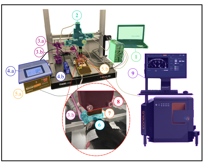
Figure 1: Experimental setup for anesthetized fUS experiments. Description of the experimental setup showing all the scientific equipment needed during an anesthetized experiment. 1. Physiological monitoring : live display of both respiratory and cardiac frequencies. 2. Four-axis motor module (three translations and one rotation) monitored by Iconeus One system (9) and allowing to perform transcranial 3D tomographic scans or 4D acquisitions. 3a. Servo-Motor driving the whisker stimulator (3b.) The servo-motor is controlled by an arduino uno card which is interfaced with the Iconeus One system (9) in order to synchronize stimulation patterns with imaging sequences. 4.a. Syringe pump controller. 4.b. Syringe holder. 5.a. Temperature plate monitor controlling the heating plate. 5.b. Heating plate and rectal thermometer interfaced with the temperature plate monitor (5.a.). 6. Ultrasound gel placed between the animal's head and the ultrasound probe, providing acoustic coupling between them. 7. 15 MHz ultrasound probe. 8. Probe holder linking the probe (7) to the motor module (2). 9. Iconeus One equipment and software, allowing programing different imaging sequences and controlling the motors module (2) driving the probe (7). Please click here to view a larger version of this figure.
2. Animal preparation for awake head-fixed mice experiments
- Headplate surgery
- Place the anesthetized animal (steps 1.1-1.2) in the stereotaxic frame on a heating pad (37 °C). Apply protective gel for the eyes and administer lidocaine s.c. (0.2 mL, 2 %) under the scalp skin using a 26-gauge needle and wait a few minutes.
NOTE: Monitor the anesthesia level every 10-30 min by response (absence of) to a firm toe pinch. - Perform an incision following the sagittal suture from behind the occipital bone to the beginning of the nasal bone. Using surgical scissors, excise the skin over both hemispheres.
- Clean the skull with 1% iodine solution and remove any remaining periosteum. Using the headplate as a template, drill two holes (1 mm diameter) in the skull to position the anchoring screws.
CAUTION: Be careful not to drill completely through the skull to avoid any brain damages or dura inflammation - Position the headplate with the screws. Use dental cement to fix the screws and the headplate in front and in the back of the frame to maintain good grip of the implant.
CAUTION: Be careful to not apply cement inside the frame window as it greatly diminishes signal quality. Cover the skull with a thin layer of surgical glue to protect the bone and seal the wounds on the side of the imaging window. - Remove the animal from the stereotaxic frame after the cement is dry and reverse the anesthesia by a subcutaneous injection of atipamezole at 1 mg/kg. A prophylactic administration of meloxicam (5 mg/kg/day, s.c.) is administered for post-operative pain.
- Place the animal in a recovery cage on a heating pad (37 °C). The mouse can return its home cage with littermates within a few hours. Place a magnetic 3D-printed cap (polyactic acid material with magnet inserts) over the headplate for protection (Figure 2A). Leave the mouse to recover for 4 to 6 days before the beginning of the habituation to the mobile home cage (MHC).
NOTE: The total weight of the cap and the headplate is 2.8 g.
- Place the anesthetized animal (steps 1.1-1.2) in the stereotaxic frame on a heating pad (37 °C). Apply protective gel for the eyes and administer lidocaine s.c. (0.2 mL, 2 %) under the scalp skin using a 26-gauge needle and wait a few minutes.
- Handling and habituation
- On day 1 post-recovery (PR), gently hold the mouse in hand for 5-10 min several times a day.
- On day 2 PR, repeat handling as in day 1 and leave the animal for 5-10 min exploring freely MHC.
NOTE: Playing some background music in the room can help reduce animal's stress. - On day 3 PR, let the animal freely explore the MHC for 5-10 min. Afterwards, carefully grab the headplate and gently place it in the clamp, moving manually the carbon cage to accompany the mouse. Habituate the animal in the head-fixed position for 5-10 min. Clean the MHC in between training sessions with 70% ethanol solution and rinse with tap water.
NOTE: Make sure that the MHC receives a sufficient air flow as recommended by the manufacturer. The height of the head clamp needs to be manually adjusted to provide a comfortable position. - On day 4 and 5 PR, repeatedly clamp the mouse MHC and gradually increase the head-fixed time, starting from 5 min and up to 30 min. Apply some saline and ultrasound gel on the imaging window to habituate.
- On day 6 PR, repeat the protocol from day 4/5 PR and position the probe above the animal's head following step 3.1.
- On the day of the experiment, proceed as described above. Then, humidify the imaging window with saline and apply some ultrasound gel. Start the tracking of the animal and proceed to the probe positioning (see below).
NOTE: Clamping in the MHC may also be done by wrapping the mouse in a rag. In that case, mice need to be habituated to the wrapping procedure before head-fixation. A description of a complete experimental setup for awake imaging is provided in Figure 2B.

Figure 2: Experimental setup for awake fUS experiments. A. Schematic illustration of the headplate magnetic cover protecting the imaging window (created with BioRender.com). During imaging sessions (Left), the cover is removed to scan the brain in the large aperture offered by the head plate. B. Photograph of the experimental setup for transcranial awake imaging in head-fixed freely-behaving mice. 1. Iconeus One system and software, allowing to set up different imaging sequences and controlling the motors module. 2. Four-axis motors module (three translations and one rotation) monitored by Iconeus One system (1) and allowing 3D tomographic scans or 4D acquisitions. 3. Air dispensing table. 4. Mobile Home Cage (MHC). 5a,5b. Photographs showing closer views of the animal's environment inside the MHC. 6. Head fixation system clamping the head plate. 7. Probe holder linking the probe to the motor module (2). 8. 15 MHz ultrasonic probe. 9. Ultrasound gel placed between the mouse head and the ultrasound probe, providing acoustic coupling between them. 10. Servo-Motor driving the whisker stimulator. The Servo-Motor is controlled by an Arduino Uno card which is interfaced with the Iconeus One system through TTL signal (1) in order to synchronize stimulation patterns with imaging sequences. C. Illustration of the different spatial sampling possibilities (created with BioRender.com): in each case, the probe is stepped from the first position to the last one and a Doppler image is recorded at each position to reconstruct the stacked volume. This process is continuously repeated during the whole acquisition time. Dense Scan (left): the step between slices must be small enough (typically 400 µm, which corresponds to the elevation resolution) to allow volumetric imaging. Sparse Scan (right): if distant functional regions are targeted (at different positions), it is also possible to decrease spatial sampling to image different slices that intersect these regions while not compromising the temporal sampling. Please click here to view a larger version of this figure.
3. Probe positioning
- Start the software (e.g., IcoScan) and create an experiment session. Go to the Move Probe menu to adjust the position of the ultrasound probe using the navigation keyboard.
NOTE: The probe should be positioned approximately 1 mm above the animal's head. It is crucial to ensure that the probe is in contact with ultrasound gel before starting any imaging sequence. - Start the Live View acquisition and adjust probe position if needed via real time imaging of the animal CBV (cerebral blood volume). Align the brain at the center of the image. Optimize the imaging parameters to capture the highest signal-to-noise ratio.
NOTE: In awake mice experiments, the aperture size needs to be reduced to avoid artefacts induced by lateral muscles contraction.
4. Angiographic scan and atlas registration
- Open the Angio 3D option in the acquisition software. On the preset panel, adjust the scanning parameters (first slice, last slice and step size) in order to scan the whole brain (Figure 3A, B), and start the acquisition.
NOTE: When setting up the scan parameters, make sure that the scan will cover the posterior part of the brain - Leave the acquisition software open and start the software for data analysis and visualization (e.g., IcoStudio), and load the angio 3D scan. Navigate through the acquisition volume using the 3-views panel and select the Coronal Scan Direction: antero-posterior or postero-anterior.
- Go to the Brain Registration Panel. Load the mouse reference template that will be needed for the registration process. Register the scan on the Allen Mouse Common Coordinates Framework using the fully automatic or the manual registration modes (Figure 3C).
- Check the result by looking at the superposition of the angio 3D scan and the reference template or by looking at the superposition of the scan and the Allen reference atlas using the Atlas Manager panel (Figure 3D). Save the registration as a .bps file.
NOTE: The registration file can be reused for any other acquisition performed during the same experiment session.
5. Brain Positioning System (BPS)
- In the IcoStudio software, make sure that the angiographic scan and its .bps file (generated in step 4.4) are loaded.
- Go to the Brain Navigation Panel. In the Atlas Manager panel, navigate through the mouse Allen brain atlas with the parent/child tree navigator. Find the anatomical targeted regions and select them to superimpose them to your scan in the 3-views.
- Visualize the targeted regions in the 3-view panel and choose an imaging plane that overlaps the targeted regions for the experiment. To do so, manually set two markers on the coronal position that includes the regions of interest.
- Click on Brain Positioning System (BPS) to extract the resulting motor coordinates. These coordinates correspond to the probe position which allows to image the targeted plane. Check the preview of the image which is computed from the angio scan.
- In the IcoScan software, enter the Probe positioning panel and click on Enter BPS coordinates. Apply the coordinates given in step 5.4. The probe moves and aligns on the targeted imaging plane.
- Perform a live view acquisition and check that the current imaging plane corresponds to the prediction given in step 5.4.
NOTE: It is also possible to select parasagittal/non orthogonal planes.
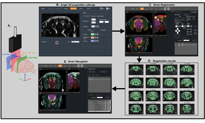
Figure 3: Fast transcranial angiographic Scan and Brain registration for precise probe positioning. A. Schematic representation of the mouse brain being scanned transcranially by the ultrasonic probe from the first coronal slice (green) to the last coronal slice (blue) during a fast angiographic scan. The current imaged slice (represented in red) moves step by step from the back (green) to the front (blue) of the brain. Created with BioRender.com B. Screenshot of IcoScan acquisition software in the Angio 3D panel. The preset parameters on the right configure the fast scan. The positions in mm of the first slice, the last slice and the step size must be well chosen to scan linearly the whole brain. C. Screenshot of the IcoStudio processing software. The fast Angio 3D scan is automatically registered to a reference template of the mouse brain. The three-views (left) shows the superposition of the vasculature and the mouse brain Allen atlas in the coronal, sagittal and axial views. D. Linear lay-out (montage) of 16 slices (out of 31) from the 3D angio scan, with the registered Allen reference atlas superimposed onto the vasculature. E. Screenshot of the Brain Navigation panel showing the predicted imaging plane corresponding to the motor coordinates computed by the software thanks to the two markers placed at the center of the left and right primary somatosensory cortex, barrel fields region. Please click here to view a larger version of this figure.
6. Task-evoked experiment: whisker stimulation
- Predefine the stimulation sequence, including time of stimulation, inter-stimulation time and number of repetitions.
- Run a 3D fUS sequence by defining the total time of acquisition, the number of positions as well as the dead-time between positions. In case of automatic stimulation synchronized with the acquisition system through TTL input, select the Trig-IN option before starting the acquisition.
NOTE: For the results presented in this work, stimulation was delivered using cotton swab positioned such as to allow deflection of most of the whiskers in the dorsal/ventral direction. It was fixed on a servo-motor driven by an Arduino UNO card, linked to the Iconeus One system to ensure synchronization. The recommended parameters for stimulation are 30 s ON, 30 s OFF, amplitude of 20° and 4 Hz frequency. Alternatively, the stimulation can also be delivered manually by deflecting the whiskers at the defined times during the acquisition. - Open the acquisition in IcoStudio software and enter the Activation map menu. Fill the activation pattern field with start and end times and compute the activation map. Adjust the display parameters for visualization. Export the activation map as a .h5 file for off-line analysis.
NOTE: Activation is estimated using a generalized linear model (GLM) approach with the stimulus convolved by a default mouse hemodynamic response (HRF). Alternatively, activation can be visualized directly by estimating the Pearson correlation between the stimulation pattern and the hemodynamic signal from each voxel.
7. 4D functional connectivity
- Run a 3D fUS sequence by defining the total time of acquisition, the number of imaging plane positions as well as the dead-time between positions.
NOTE: For 4D functional connectivity, we recommend acquisition time between each volume < 2.5 s (sampling frequency of at least 0.4 Hz) and a total acquisition time of at least 10 min (number of time points > 180). - Save the acquisition and load it in the IcoStudio software. If necessary, load the .bps file and the Allen mouse brain coordinate framework. In the Atlas manager, select regions of the atlas as regions of interest (ROI).
- Enter the Functional Connectivity menu and select the desired regions in the ROI manager. Visualize the results as connectivity matrix (supervised analysis) or seed-based correlation map (unsupervised). Select and adjust the bandwidth filters as desired and export correlation results for statistical analysis.
NOTE: In 3D fUS imaging mode, the relative probe positions are set manually. Hence, two types of scans are possible and can be chosen depending on the functional application: dense scans versus sparse scans (Figure 2C).
Results
This protocol describes the 3D quantification of cerebral hemodynamic variations transcranially in the mouse brain, at rest or in response to sensory stimulation. Whisker stimulation, a standard paradigm to map brain functional activation in rodents, has been selected as an example of sensory stimulation-evoked response. Figure 4 shows a representative activation map in response to mechanical whisker stimulation in an anesthetized mouse obtained using transcranial fUS imaging. The total trial time was 760 s, with a 60 s baseline (before and after the stimulation), an 80 s stimulation and a 60 s recovery time, repeated 5x. Significant activation was determined with the resolution of a general linear model (GLM) using a default mouse hemodynamic response function (HRF). The activated regions (Z scores with p-value >0.0000006 after stringent Bonferroni correction for multiple comparison) are displayed as color-coded values overlaid onto the Allen common coordinate framework template. Voxel-wise time course of the contralateral primary somatosensory cortex, barrel field region (S1BF) revealed a 15-20% increase of the CBV compared to baseline.
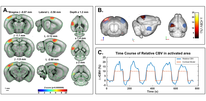
Figure 4: Transcranial activation Maps and rCBV time course following whiskers stimulation in ketamine/xylazine anesthetized mouse. A. Activation map showing significantly activated voxels following mechanical stimulation of the right whiskers (80 s ON, 60 s OFF ,5x) under ketamine/xylazine anesthesia. Maps were obtained by computing Z-scores based on general linear model analysis (GLM) with Bonferroni correction for multiple comparison. Z-scores (color coded) are overlaid on the Allen brain 3D template (after registration with the brain positioning system) and displayed in three-views: coronal (left), sagittal (middle) and axial (right). Anatomical regions from the Allen mouse brain common coordinate framework are displayed for reference. Activated voxels are well located inside the left S1BF cortex. Scale bar: 1 mm. Each sample volume was scanned over 2.8 mm (corresponding to 7 slices in the elevation direction) in 3.85 s allowing to record 20 volumic samples during each functional response. B. 3D rendering of whisker stimulation-evoked relative cerebral blood volume (rCBV) increase compared to baseline level. The anatomical delineation of the S1BF is indicated in blue. C. Time course of CBV variations in the left S1BF (blue) and the corresponding stimulus applied (red). Please click here to view a larger version of this figure.
The same paradigm has been applied in a head-fixed behaving mouse in the mobile homecage using the awake preset of IcoScan. Figure 5 presents the activation map after a multiple whisker stimulation experiment using the experimental setup described in Figure 2. A few posterior and caudal whiskers were stimulated with the following pattern: 30 s baseline followed by five consecutive trials of 30 s ON (4 Hz) and 30 s OFF (Figure 5C). Stimulation was delivered using a servo-motor driven by an Arduino UNO card triggering the image acquisition sequence for synchronization. Significant activation was determined with the resolution of a general linear model (GLM) using a default mouse hemodynamic response function (HRF). Multiple comparison correction was performed with the Bonferroni method. Conventional alpha level of 0.05 was normalized by the total number of voxels in the acquisition volume, resulting in a final stringent threshold of 0.000003.

Figure 5: Activation Maps and rCBV time course following whiskers stimulation in awake behaving mouse. A. Activation map showing significantly activated voxels following mechanical stimulation of the right whiskers (30 s ON, 30 s OFF, 5x) in an awake mouse in the mobile homecage. Maps were obtained by computing Z-scores based on general linear model analysis (GLM) with Bonferroni correction for multiple comparison (normalization by the total number of voxels). Z-scores (color coded) are overlaid on the Allen brain 3D template (after registration with the Brain Positioning System) and displayed in three-views: coronal (left), sagittal (middle) and axial (right). Anatomical regions from the Allen Mouse Brain Common Coordinate Framework are displayed for reference. Activated voxels are well located inside the left S1BF cortex. Scales bars, 1 mm. Each sample volume was scanned over 1.6 mm (corresponding to 3 slices in the elevation direction) in 3.85 s allowing to record 17 volumic samples during each functional response. B. 3D rendering of whisker stimulation-evoked relative Cerebral Blood Volume (rCBV) increase compared to baseline level. The anatomical delineation of the S1BF is indicated in blue. C. Illustration of the mouse in the mobile homecage during the right whisker stimulation experiment, during which five 30 s trials were performed for a total acquisition time of 330 s. D. Instantaneous relative CBV time course extracted inside the activated area (blue), with the corresponding stimulus superimposed (red). Please click here to view a larger version of this figure.
Figure 6 shows the temporal correlations of normalized low-frequency (<0.2 Hz) spontaneous CBV fluctuations between 3D brain regions (identified from registration to the Allen common coordinate framework) in a ketamine-xylazine anesthetized mouse. Total acquisition time was 20 min (1200 s). Atlas-supervised analysis revealed strong interhemispheric connectivity patterns, with resulting correlation coefficient values up to 0.8. Seed-based analysis in the dorsal hippocampus revealed a significant interhemispheric connectivity between right and left hippocampus as well as deep retro-hippocampal regions and piriform cortices. A seed region selected in the S1BF also resulted in a symmetrical (cortico-cortical) correlation pattern, as previously described.

Figure 6: Transcranial volumetric resting-state functional connectivity of the mouse brain under ketamine/xylazine anesthesia assessed on a 20 min 3D fUS acquisition. A. Correlation matrix based on 3D regions of the Allen common coordinate framework registered on the transcranial functional acquisition. The matrix is obtained by computing the normalized Pearson's correlation of spontaneous low-frequency fluctuations (<0.1 Hz) of the average time signals from all the voxels included in each identified ROI after slice timing correction. Each sampled volume was scanned over 1.6 mm in the elevation direction (corresponding to 4 slices) acquired over 2.2 s. B. Seed-based analysis projected onto a 3D template. The seed was selected within the right dorsal hippocampus at β - 2.1 mm. Correlation map is obtained by computing the Pearson Correlation coefficient between the temporal signals of the seed and each voxel of the whole acquisition after slice timing correction. C. 3D correlation map based on seed-based analysis with seed region selected within the S1BF at β - 2.1 mm. Scale bars: 1 mm. Please click here to view a larger version of this figure.
Discussion
Whole brain imaging methods are crucial tools to better understand brain physiology and pathology. The method described here allows the precise quantification of hemodynamic signals in the living brain directly at the bench. The unmatched sensitivity and spatio-temporal resolution of functional ultrasound is particularly well suited for the mouse physiology. Functional responses and resting-state networks can be mapped within short acquisition times, longitudinally and without having to average trials or subjects to obtain a reliable measure. The relevant combination of high sensitivity ultrasonic linear probes and fast motorized setups enables one to perform transcranial volumetric fUS imaging in mice within reasonable acquisition times. This protocol can be performed either on anesthetized or awake mice using a mobile home cage.
Whisker stimulation, the sensory stimulus used as an illustrating example in this manuscript, is a standard functional activation paradigm in rodents and a reliable read-out to study sensory processing, neurovascular coupling and their alterations5,6,10, 11. While coarse manual brushing of the whiskers may be preferred for its ease of use, this method lacks spatial and temporal precision. The use of an automatic stimulator, such as the one described here triggered with the fUS imaging scanner, allows for a better control of several parameters including the time of onset, the amplitude displacement, the frequency as well as the angle of the Q-tip/comb, resulting in a better inter-animal reproducibility. Additionally, a more precise timing of stimulation enables the modeling of the Hemodynamic Response Function (HRF) by determining the time to onset and time to peak parameters12,13. To ensure better precision on the number of whiskers deflected during the stimulation (and thus the area of the activated region), more sophisticated stimulators can be adapted to this protocol. Many other stimuli such as light8, sound14 or odor presentation15 can be implemented using the same protocol.
The compatibility of functional ultrasound with awake and behaving animals is an important advantage compared to other neuroimaging techniques, enabling functional activation mapping without the anesthesia bias. Using an air-lifted mobile homecage is a good alternative to other existing head-fixed apparatus such as linear or spherical treadmills. While being firmly head-fixed, the motion of the homecage gives the mouse the illusion to navigate the environment, allowing a wide-range of behavioral testings to be coupled to fUS imaging16. However, the habituation procedure to head-fixing constitutes an important step to decrease stress, especially for experiments where it can be considered a confounding factor. The procedure detailed here (6-days of handling and habituation to head fixation) gives robust results for sensory stimulation and resting-state functional connectivity. However, it might be necessary to extend the habituation period for more refined behavioral tests17.
Disclosures
Jeremy Ferrier and Bruno-Félix Osmanski are employees of Iconeus. Thomas Deffieux, Zsolt Lenkei, Bruno-Félix Osmanski, and Mickael Tanter are co-founders and shareholders of Iconeus.
Acknowledgements
This work was supported by the European Research Council (ERC) Advanced Grant N° 339244-FUSIMAGINE, the National Agency for Research funding 'Pinch' (ANR-18-CE37-005), the Inserm Research Technology Accelerator in Biomedical Ultrasound, the ElfUS technical core of the IPNP, Inserm U1266, the European research program FUSIMICE of the Human Brain Project, and EMBO Short-Term Fellowship 8439 to Andrea Kliewer.
Materials
| Name | Company | Catalog Number | Comments |
|---|---|---|---|
| BD Plastipak 1 mL syringes | Dutscher, France | 303172 | |
| BD Microlance 26 Gauge needles | Dutscher, France | 303800 | |
| Animal Temperature Controller (heating Plate coupled with a rectal probe) | Physitemp | TCAT-2DF | |
| Arduino | Arduino | Arduino Uno-Rev3 | |
| Atipamezole | Orion Pharma, France | Antisedan® | 5 mg/ml injectable solution |
| Dental Ciment | Sun Médical, Shiga, japan | Superbond C&B | |
| Depilatory cream | Klorane | N/A | |
| Eye Ointment | TVM, UK | Ocry-gel | |
| Hair trimmer | Wella Profesionnals | N/A | |
| Head plates | Neurotar, Finland | Model 14 | |
| Iconeus One standard package for fUS | Iconeus, France | Iconeus One | |
| IcoScan acquisition software (v1.0) | Iconeus, France | IcoScan | |
| IcoStudio analysis software (v1.0) | Iconeus, France | IcoStudio | |
| Isoflurane Anesthesia station | Minerve, Esternay, France | ||
| Ketamine | Virbac, France | Ketamine1000 | 100 mg/ml injectable solution |
| Lidocaine | Vetoquinol | Lurocaine® | 20 mg/ml injectable solution |
| Medetomidine | Orion Pharma, France | Domitor® | 1 mg/ml injectable solution |
| Meloxicam | Boehringer lingelheim | Metacam® | 0.5 mg/ml injectable solution |
| Mobile HomeCage Large with tracking capability | Neurotar, Finland | MHC-L-T-V4 | |
| Monitoring of ECG and breathing rate | AD Systems, (USA) and LabChart software | ||
| Servomotor | Feetech | FT90B | |
| Stereotaxic frame | David Kopf (Tujunga, USA) | 900-WA | Using Mouse Adaptor (Ref: 922) and Non-Rupture Ear Bars (ref: 922) |
| Surgical glue | 3M, USA | Vetbond | |
| Syringe Pump | KD Scientific, USA | Legato® 130, Cat# 788130 | |
| Ultrasound gel | DREXCO medical, France | Medi'Gel | |
| Xylazine 2% | Bayer, France | Rompun® | 20 mg/ml injectable solution |
References
- Hoyer, C., Gass, N., Weber-Fahr, W., Sartorius, A. Advantages and challenges of small animal magnetic resonance imaging as a translational tool. Neuropsychobiology. 69 (4), 187-201 (2014).
- Deffieux, T., Demene, C., Pernot, M., Tanter, M. Functional ultrasound neuroimaging: a review of the preclinical and clinical state of the art. Current Opinion in Neurobiology. 50, 128-135 (2018).
- Rabut, C., et al. Pharmaco-fUS: Quantification of pharmacologically-induced dynamic changes in brain perfusion and connectivity by functional ultrasound imaging in awake mice. NeuroImage. 222, 117231(2020).
- Tiran, E., et al. Transcranial functional ultrasound imaging in freely moving awake mice and anesthetized young rats without contrast agent. Ultrasound in Medicine and Biology. 43 (8), 1679-1689 (2017).
- Ferrier, J., Tiran, E., Deffieux, T., Tanter, M., Lenkei, Z. Functional imaging evidence for task-induced deactivation and disconnection of a major default mode network hub in the mouse brain. Proceedings of the National Academy of Sciences of the United States of America. 117 (26), 15270-15280 (2020).
- Rabut, C., et al. 4D functional ultrasound imaging of whole-brain activity in rodents. Nature Methods. 16 (10), 994-997 (2019).
- Brunner, C., et al. A platform for brain-wide volumetric functional ultrasound imaging and of circuit dynamics in awake mice. Neuron. 108 (5), 861-875 (2020).
- Gesnik, M., et al. 3D functional ultrasound imaging of the cerebral visual system in rodents. NeuroImage. 149, 267-274 (2017).
- Macé, É, et al. Whole-brain functional ultrasound imaging reveals brain modules for visuomotor integration. Neuron. 100 (5), 1241-1251 (2018).
- Macé, E., Montaldo, G., Cohen, I., Baulac, M., Fink, M., Tanter, M. Functional ultrasound imaging of the brain. Nature Methods. 8 (8), 662-664 (2011).
- Tiran, E., et al. Transcranial functional ultrasound imaging in freely moving awake mice and anesthetized young rats without contrast agent. Ultrasound in Medicine and Biology. 43 (8), 1679-1689 (2017).
- Claron, J., et al. Large scale functional ultrasound imaging of the spinal cord reveals in depth spatiotemporal responses of spinal nociceptive circuits in both normal and inflammatory state. Pain. , (2020).
- Aydin, A. K., et al. Transfer functions linking neural calcium to single voxel functional ultrasound signal. Nature Communications. 11 (1), 2954(2020).
- Bimbard, C., et al. Multi-scale mapping along the auditory hierarchy using high-resolution functional ultrasound in the awake ferret. eLife. 7, 35028(2018).
- Boido, D., et al. Mesoscopic and microscopic imaging of sensory responses in the same animal. Nature Communications. 10 (1), 1110(2019).
- Kislin, M., et al. Flat-floored air-lifted platform: A new method for combining behavior with microscopy or electrophysiology on awake freely moving rodents. Journal of Visualized Experiments. (88), e51869(2014).
- Juczewski, K., Koussa, J. A., Kesner, A. J., Lee, J. O., Lovinger, D. M. Stress and behavioral correlates in the head-fixed method: stress measurements, habituation dynamics, locomotion, and motor-skill learning in mice. Scientific Reports. 10 (1), 12245(2020).
Reprints and Permissions
