Source: Peiman Shahbeigi-Roodposhti and Sina Shahbazmohamadi, Biomedical Engineering Department, University of Connecticut, Storrs, Connecticut
For over 4000 years, sutures have been used as a medical intervention. The earliest records indicate linen was the biomaterial of choice. Catgut, which is still in use today, was reportedly used to treat gladiators around 150 AD. Today, there are numerous materials being used for sutures. Sutures are classified by their composition (natural or synthetic) and their absorption (non-resorbable or resorbable).
Resorbable (or absorbable) sutures degrade in the body through either enzymatic degradation or programmed degradation caused by the interaction of water with specific groups in the polymer chain. These sutures are often created from synthetic materials, such as polyglycolic acid, polydioxanone, and polycaprolactone, or natural biomaterials, such as silk. They are usually used for certain internal procedures, like general surgery. Resorbable sutures will hold the wound together for a time frame long enough for healing, but then they eventually disintegrate by the body. On the other hand, non-resorbable sutures do not degrade and must be extracted. They are usually derived from polypropylene, nylon, and stainless-steel. These sutures are usually implemented for orthopedic and cardiac surgery and require a medical professional to remove them at a later date.
Here, the tensile strength of two types of resorbable sutures will be tested after exposing them to neutral, acidic, and alkaline solutions, which correspond to the different pH environments found within the human body. The test will consist of two parts. First, control samples will be prepared and analyzed via tensile testing. Then, samples will be tested after the continuous exposure to solutions of varying pH over the course of several weeks.
Biomedical Engineering
Source: Peiman Shahbeigi-Roodposhti and Sina Shahbazmohamadi, Biomedical Engineering Department, University of Connecticut, Storrs, Connecticut
Nanoparticles have been increasingly used research towards targeted drug delivery and controlled drug release. While most of these particles have been developed as polymeric or liposomal particles because of their biocompatibility, there is a trend in current research toward the use of metallic and magnetic nanoparticles. These metallic nanoparticles were originally used as a contrast agent in imaging, but recent advances have shown how important they could be in drug and gene delivery and in therapeutics. Gold, silver, and paramagnetic nanoparticles have the greatest share in research being done. They have been shown to have good biocompatibility and certain varieties of magnetic nanoparticles have already been developed and distributed as therapeutic targeted drugs.
These heavy elements are typically imaged for research using fluorescence to evaluate delivery and distribution, but their atomic weights are good qualifications for increased contrast in backscatter electron analysis using a scanning electron microscope (SEM). Energy dispersive X-ray spectroscopy, which uses characteristic X-rays emitted upon electron beam interaction with the sample to identify chemical composition, can also be used with the SEM. These methods have the benefits of increased resolution and increased confidence in detection, as the EDS can ensure that the subject of an image is of the right composition, while current fluorescence methods can detach from the nanoparticles and can fade quickly while imaging.
This demonstration will examine the size-dependent metal nanoparticle distribution in organs of the body over time. Excised organs will be examined with SEM for various sizes of particles at a range of time points after particle delivery to the body.
Biomedical Engineering
Source: Peiman Shahbeigi-Roodposhti and Sina Shahbazmohamadi, Biomedical Engineering Department, University of Connecticut, Storrs, Connecticut
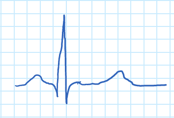
An electrocardiograph is a graph recorded by electric potential changes occurring between electrodes placed on a patient's torso to demonstrate cardiac activity. An ECG signal tracks heart rhythm and many cardiac diseases, such as poor blood flow to the heart and structural abnormalities. The action potential created by contractions of the heart wall spreads electrical currents from the heart throughout the body. The spreading electrical currents create different potentials at points in the body, which can be sensed by electrodes placed on the skin. The electrodes are biological transducers made of metals and salts. In practice, 10 electrodes are attached to different points on the body. There is a standard procedure for acquiring and analyzing ECG signals. A typical ECG wave of a healthy individual is as follows:

Figure 1. ECG wave.
The "P" wave corresponds to atrial contraction, and the "QRS" complex to the contraction of the ventricles. The "QRS' complex is much larger than the "P" wave due to the relative dfference in muscle mass of the atria and ventricles, which masks the relaxation of the atria. The relaxation of the ventricles can be seen in the form of the "T" wave.
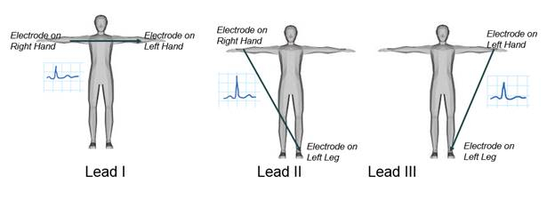
There are three main leads responsible for measuring the electrical potential difference between arms and legs, as shown in Figure 2. In this demonstration, one of the limb leads, lead I, will be examined, and the electrical potential difference between two arms will be recorded. As in all ECG lead measurements, the electrode connected to the right leg is considered the ground node. An ECG signal will be acquired using a biopotential amplifier and then displayed using instrumentation software, where a gain control will be created to adjust its amplitude. Finally, the recorded ECG will be analyzed.

Figure 2. ECG limb leads.
Biomedical Engineering
Source: Peiman Shahbeigi-Roodposhti and Sina Shahbazmohamadi, Biomedical Engineering Department, University of Connecticut, Storrs, Connecticut
It's a little-known fact that the discovery and (inadvertent) use of X-rays garnered the first ever Nobel Prize in Physics. The famous X-ray image of Dr. Röntgen's wife's hand from 1895 that sent shock waves through the scientific community looks like most modern day 2D medical X-ray images. Though it is not the newest technology, X-ray absorption imaging is an indispensable tool and can be found in the world's top R&D and university labs, hospitals, airports, among other places. Arguably the most advanced uses of X-ray absorption imaging involve attaining information like the kind found in a 2D medical X-ray but realized in 3D through a computed tomography (CT or micro-CT). By taking a series of 2D X-ray projections, advanced software is capable of reconstructing data to form a 3D volume. The 3D information can, and most likely will include information from the inside of the probed object without having to be cut open. Here, a micro-CT scan will be obtained, and the major factors impacting image quality will be discussed.
Biomedical Engineering
Source: Peiman Shahbeigi-Roodposhti and Sina Shahbazmohamadi, Biomedical Engineering Department, University of Connecticut, Storrs, Connecticut
Optical microscopes have been around for centuries, and while they reached their theoretical limitation of resolution decades ago, new equipment and techniques, such as confocal and digital image processing, have created new niches within the field of optical imaging. The best optical microscopes will typically have a resolution down to 200 nm in ideal conditions. However, optical microscopes are limited by the diffraction of waves, a function of the wavelength, which is around 500 nm for visible light. While the resolution of optical microscopes does not reach that of electron microscopes, they are the most valuable tools in the imaging of biological macrostructures and are a staple in any biological lab.
In conventional light microscopes, the signal produced from the imaged object is from the full thickness of the specimen, which does not allow most of it to be in focus to the observer. This causes the image to have "out of focus blur". The confocal microscope, on the other hand, illuminates the sample through a pin-hole, and is therefore able to filter out the out-of-focus light from above and below the point of focus in the object.
This demonstration provides an introduction to image acquisition using optical and confocal microscopy methods. Here, a sectioned piece of mouse brain will be studied. Image acquisition and analysis, including the tools to generate topographical maps and composite images, will be covered. The advantages and disadvantages of different imaging methods as they relate to resolution, depth of focus and sample type will also be discussed. The purpose of this demonstration is to provide more information on optical and confocal microscopes to determine if these microscopy modules are the best fit for a type of biological sample.
Biomedical Engineering
Source: Sina Shahbazmohamadi and Peiman Shahbeigi-Roodposhti-Roodposhti, School of Engineering, University of Connecticut, Storrs, CT
Bones are composites, made of a ceramic matrix and polymer fiber reinforcements. The ceramic contributes compressive strength, and the polymer provides tensile and flexural strength. By combining ceramic and polymer materials in different amounts, the body can create unique materials tailored for a specific application. As biomedical engineers, having the ability to replace and replicate bone due to disease or traumatic injury is a vital facet of medical science.
In this experiment we will create three different ceramic-matrix composites with plaster of Paris (which is a calcium sulfate compound), and allow them to undergo three-point bending test in order to determine which preparation is the strongest. The three composites are as follows: one comprised only of plaster of Paris, one with chopped glass shards mixed in a plaster matrix and lastly a plaster matrix with a fiberglass network embedded within it.
Materials Engineering
Source: Sina Shahbazmohamadi and Peiman Shahbeigi-Roodposhti-Roodposhti, School of Engineering, University of Connecticut, Storrs, CT
As electron microscopes become more complex and widely used in research labs, it becomes more of a necessity to introduce their capabilities. Focused ion beam (FIB) is an instrument that can be employed in order to fabricate, trim, analyze and characterize materials on mico- and nano-scales in a wide variety of fields from nano-electronics to medicine. FIB systems can be thought of as a beam of ions that can be used to mill (sputter), deposit, and image materials on micro- and nano-scales. The ion columns of FIBs are commonly integrated with the electron columns of scanning electron microscopes (SEMs).
The goal of this experiment is to introduce the state of the art in focused ion beam technologies and to show how these instruments can be used in order to fabricate structures that are as small as the smallest membranes that are found in the human body.
Materials Engineering
Source: Sina Shahbazmohamadi and Peiman Shahbeigi-Roodposhti-Roodposhti, School of Engineering, University of Connecticut, Storrs, CT
Alloys with grain size less than 100 nm are known as nanocrystaline alloys. Due to their enhanced physical and mechanical properties, there is an ever-increasing demand to employ them in various industries such as semiconductor, biosensors and aerospace.
To improve the processing and application of nanocrystalline alloys, it is necessary to develop close to 100% dense bulk materials which requires a synergistic effect of elevated temperature and pressure. By increasing the applied temperature and pressure, small grains start to grow and lose their distinguished properties. Thus, it is technologically important to reach a compromise between inter-particle bonding with minimum porosity and loss of nano-scale grain size during consolidating at elevated temperatures.
In this study we aim to eliminate oxygen from solid solution to improve the nano-grain size stability at elevated temperatures. Nano-crystalline Fe-14Cr-4Hf alloy will be synthesized in a protected environment to avoid oxide particles formation.
Materials Engineering
Source: Sina Shahbazmohamadi and Peiman Shahbeigi-Roodposhti-Roodposhti, School of Engineering, University of Connecticut, Storrs, CT
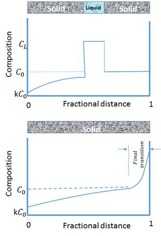
Directional solidification zone melting is a metallurgical process in which a narrow region of a crystal (usually in the form of bar) is melted. The furnace moves along the rod shape sample, meaning that the molten zone is moved along the crystal and the molten zone is moved from one end of the bar to the other. This mechanism is widely used in alloys, however solute atoms tend to segregate to the melt. In this type of alloy, the impurities also concentrate in the melt, and move to one end of the sample along with the moving molten zone. Therefore, zone melting is used most extensively for commercial material refining. Fig. 1. shows how the high-impurity molten-zone moves from one side of the bar to the other. The vertical axis is the impurity concentration and the horizontal axis is the sample length. Due to the tendency for impurities to segregate to the molten region, its concentration in the melt is higher than in the solid. Therefore, as the molten materials travel to the end of bar, the impurity will be transported to the end of bar and leave the high purity solid material behind it.

Figure 1: Schematic of the composition change during zone melting directional solidification.
In this study, a zone melting directional solidification apparatus will be employed to synthesize stable structures of Pb-Cd alloys.
Materials Engineering
Source: Peiman Shahbeigi-Roodposhti and Sina Shahbazmohamadi, Biomedical Engineering Department, University of Connecticut, Storrs, Connecticut
A scanning electron microscope (SEM) is an instrument that uses an electron beam to nondestructively image and characterize conductive materials in a vacuum. As an analogy, an electron beam is to the SEM as light is to the optical microscope. The difference is that the electron microscope yields images of much higher resolution and magnification. The best optical microscopes typically have a resolution down to 200 nm, whereas SEMs usually claim a resolution of 0.5 nm. This is due to the fact that optical microscopes are limited by the diffraction of waves, a function of the wavelength, which is around 500 nm for visible light. Conversely, the SEM uses an energized electron beam, which as a wavelength of 1 nm. This characteristic makes them very dependable tools for the study of nano and microstructures. Electron microscopes also enable the study of biological samples with feature sizes too small for optical microscopy.
This demonstration provides an introduction to sample preparation and initial image acquisition of biological samples using a scanning electron microscope. In this case, a collagen-hydroxyapatite (HA) cellular scaffold will be studied. The vacuum environment of the SEM and the induced charging by the electron beam on non-conductive samples (such as organic matter) creates challenges that will be addressed in the preparation. The advantages and disadvantages of different imaging methods as they relate to resolution, depth of focus and sample type will also be discussed. The purpose of this demonstration is to give the participant more information on SEM to determine if this microscopy module is the best fit for a type of biological sample.
Biomedical Engineering
