

Summary
A procedure for thermochemical conversion of biomass residues is presented that aims at maximizing the yield of liquid products (fast pyrolysis). It is based on a technology proven on an industrial scale and especially suitable for treating a straw type of biomass.
Abstract
Fast pyrolysis is being increasingly applied in commercial plants worldwide. They run exclusively on woody biomass, which has favorable properties for conversion with fast pyrolysis. In order to increase the synergies of food production and the energetic and/or material use of biomass, it is desirable to utilize residues from agricultural production, e.g., straw. The presented method is suitable for converting such a material on an industrial scale. The main features are presented and an example of mass balances from the conversion of several biomass residues is given. After conversion, fractionated condensation is applied in order to retrieve two condensates — an organic-rich and an aqueous-rich one. This design prevents the production of fast pyrolysis bio-oil that exhibits phase separation. A two phase bio-oil is to be expected because of the typically high ash content of straw biomass, which promotes the production of water of reaction during conversion.
Both fractionated condensation and the use of biomass with high ash content demand a careful approach for establishing balances. Not all kind of balances are both meaningful and comparable to other results from the literature. Different balancing methods are presented, and the information that can be derived from them is discussed.
Introduction
The use of biomass as an alternative to fossil carbon sources is becoming increasingly important for reducing the effect of societal activity on the earth's climate. There exist other renewable energy sources such as wind and solar, but biomass represents the only renewable carbon source to date. Consequently, the most efficient use of biomass is in the production of chemicals and specialized liquid fuels. Residual biomass should be used in order to reduce competition between feed, food, and chemicals/fuel production. These residues often have low bulk density, thus presenting a logistical challenge for industrial scale applications.
To address these challenges, the bioliq concept has been developed at the Karlsruhe Institute of Technology1. It features a decentralized first step to convert residual biomass into an energy dense intermediate (bioslurry), a subsequent conversion in a central gasification unit to synthesis gas and a final synthesis to the desired product(s). The gasification and synthesis unit can be designed on the required industrial scale at the same site to achieve commercial operation. The concept allows for different products, ranging from drop-in fuels to specialized fuel additives and bulk chemicals2-5. This paper presents the first step in which fast pyrolysis is used to convert residual biomass to the intermediate bioslurry. Fast pyrolysis is characterized by rapid heating of biomass in an inert atmosphere to a reaction temperature of typically 450-500 °C with a residence time of the produced pyrolysis vapors of <2 sec6. Most commonly, fluidized bed reactors are used for performing fast pyrolysis but there also exist different reactor designs specifically adapted to optimize reaction conditions7. The work presented in the following has been conducted with a twin-screw mixing reactor. It presents a robust technology that has already been applied on an industrial scale for pyrolysis of coal and on a pilot scale for oil sands8.
The purpose of the twin-screw mixing reactor is to mix the solid biomass feed with a solid, pre-heated heat carrier. Mixing needs to be sufficiently thorough in order to achieve the heating rate that is necessary for converting the biomass under fast pyrolysis conditions. Additionally, the size of both the biomass and heat carrier particles needs to be small to achieve a high heat transfer coefficient and a short particle heating period. At the Institute of Catalysis Research and Technology (IKFT) of the Karlsruhe Institute of Technology (KIT), a process development unit with a biomass input capacity of 10 kg hr-1 has been operational for more than a decade. It uses steel balls as the heat carrier, which is recirculated internally with a bucket elevator and re-heated with an electrical heating system. Its main purpose was the investigation of a unique product recovery technology that was adapted to the use of the product in a gasifier and the validation of its suitability for a broad range of feedstocks9-11. A larger pilot plant was built in parallel to these studies with a biomass input capacity of 500 kg hr-1, which has been operational for five years. It utilizes sand as the heat carrier, which is recirculated pneumatically by a hot lift gas and additionally heated by partial combustion of entrained char particles1,12. The following description of the experimental method is based on the smaller process development unit after its product recovery section was refurbished to better resemble the pilot plant design13. A flow scheme of this experimental setup is illustrated in Figure 1.
It is important to note that product requirements for fast pyrolysis bio-oil (FPBO) for use in gasifiers are different to those developed for conventional FPBO, which is usually intended for direct fuel applications14. Most importantly, the solids content of the FPBO does not have to be very low. In fact, it is desirable to mix the FPBO produced with the char obtained from the conversion process in order to increase the amount of carbon available for gasification and subsequent synthesis of drop-in fuels. These facts are important for understanding the differences in the design of the experimental setup presented here and fast pyrolysis experiments published elsewhere. Another important difference is the fact that the biomass conversion concept under investigation was specifically designed for agricultural residues such as wheat straw. Typically, this kind of feedstock contains a large fraction of ash. Ash is known to significantly influence the product distribution of fast pyrolysis. It leads to a decrease of organic condensate (OC) and an increase in both solid and gaseous products10,15,16. These facts are accounted for both in the design of the experimental setup presented here and the overall process chain. Most industrial installations run on wood with low ash content and simply burn the solids internally. This leads to additional production of heat for external use. When using feedstocks with high ash content, char is a significant by-product that should be used efficiently13.
Protocol
1. Start-up
- Activate the whole pyrolysis and condensation system by starting the auxiliary N2 supply and the pyrolysis gas fan. Flush the pyrolysis test rig with 500 L hr-1 of nitrogen during standby. Regulate the fan by opening the fan's menu in the process control and adjusting its nominal volumetric flow such that the pressure in the reactor is 3-8 mbar above ambient pressure.
Caution: Especially during start-up, there is an increased risk of build-up of explosive atmospheres. The system must be completely inert in order to mitigate this risk. - Fill the bio-oil cycle (i.e., organic-rich condensate) with an appropriate amount of ethylene glycol as the starting medium for the quenching system to allow safe operation of the pump and homogenizer (e.g., 15 kg in the example given). Record the weight of the starting material.
- Fill the aqueous condensate cycle with an appropriate amount of water to allow safe operation of the pump (e.g., 7 kg in the example given). Record the weight of starting material.
- Heat up the system, including the heat carrier heater and all auxiliary heaters, by opening their menus in the process control and entering the desired values (e.g., around 500 °C). Auxiliary heating is recommended for the reactor itself and the connecting pipes up to the first condenser in order to prevent uncontrolled condensation of vapors.
- Start the cooling cycle for the heat exchangers in both condensation cycles by switching on the cooler.
- Start the pumps of both condensation cycles by opening their menus in the process control and click on activate. Use the same menus to adjust the mass flow to provide enough cooling power. For example, recirculate the bio-oil at a rate of around 350 kg hr-1 and cool it down to 80 °C before spraying it into the quenching vessel. Recirculate the aqueous condensate at a rate of around 600 kg hr-1 and, in addition, supply cooling water at a rate of 300 kg hr-1 at 8 °C.
- Switch on the electrostatic precipitator.
- After both condensation cycles have run for 10-20 min, check the nozzles of the quenching system for blocking and remove any blockage present.
- Start the heat carrier loop by opening the menu of the bucket elevator and the heat carrier feeding screw in the process control and click on activate. Set the heat carrier temperature to a value above the desired reactor temperature in order to allow a smoother start-up by accounting for the heat requirements for the pyrolysis reaction. For example, supply the heat carrier with a mass flow of 1,000 kg hr-1 at a temperature of 520 °C during operation, but heat to 545 °C before starting the biomass feed.
Caution: Make sure that the twin-screws of the reactor are started automatically once the heat carrier feeding screw is activated. Otherwise there is the risk of blocking and even damage to the feeding system. - After the system (i.e., all temperatures) has reached the set values, start feeding biomass by filling the biomass storage with the desired feedstock. Subsequently, open the lock hopper and start the biomass feeding screw by clicking on activate in their menus in the process control. Slowly increase the feed rate in order to prevent excessive pressure fluctuations.
2. Steps and Observations Continuously Required during Operation
- Record the amount of biomass fed in order to account for balancing and take appropriate samples.
- Check for the desired reactor temperature (exit temperature of the heat carrier) and regulate the heating of the heat carrier loop accordingly.
- Regulate the fan by adjusting its nominal volumetric flow to keep the desired reactor pressure.
- Check for blocking in the nozzles of the quenching system (drop in mass flow and/or increase in quenching temperature).
- Observe the pressure drop across the cyclones and the quenching system in order to detect excessive scaling early enough. Install appropriate measures to be able to remove excessive scaling during operation, especially at the point of the first temperature drop of the pyrolysis vapors (usually the inlet of the quenching system).
- For example, clean the tube's cross section by using a rod to remove scaling mechanically. Seal the rod with a gasket to prevent intake of air into the quenching system. Install a ball valve at the inlet point of the rod to further decrease air leakage if the cleaning is not in operation.
Caution: Cleaning the inlet of the quenching system by inserting a rod leads to temporary blockage of the gas removal from the reactor. Biomass feeding must be stopped if it cannot be assured that the cleaning is performed in <10 sec.
- For example, clean the tube's cross section by using a rod to remove scaling mechanically. Seal the rod with a gasket to prevent intake of air into the quenching system. Install a ball valve at the inlet point of the rod to further decrease air leakage if the cleaning is not in operation.
- Monitor the condensation temperatures of both condensation cycles and adapt the temperature set-points of the process thermostats if necessary.
- Remove condensate from cycles as soon as 80% of the maximum allowable filling level has been reached (depending on the size of the buffer tanks and the amount and type of biomass fed).
- Conduct measurements of the gas phase. Measure the amount of gas as well as its composition (see details in step 4.5).
NOTE: Primary gaseous compounds include N2, CO, CO2, CH4, O2, and H2. Additional compounds are to be expected, such as C2H4, C2H6, and C3H8. An example of a gas measurement system is described below (see step 4.5).
Caution: If parts of the pyrolysis unit are operated under pressure, leakage of air may lead to the development of an explosive atmosphere. It is highly recommended to closely observe the amount of oxygen in the pyrolysis gas.
3. Shutdown
- To stop the experiment, simply turn off the biomass feed and regulate the fan to keep the desired reactor pressure.
- Allow the system (heat carrier loop and condensation cycles) to run for another 30-40 min to ensure that all remainders are pyrolyzed and the products recovered.
- Turn off the heating of the heat carrier loop.
- Turn off the pumps of both condensation cycles and the electrostatic precipitator.
- Empty both condensate cycles and record the weight of each condensate. Subtract the amount of starting material (see steps 1.2 and 1.3) before setting up the balances.
- Allow the containers for char collection to cool down to room temperature in an inert atmosphere. Weigh the amount of char.
Caution: The char may exhibit pyrophoric characteristics, and specific care should be taken when handling this material. - Clean the bio-oil cycle with fresh ethylene glycol and the aqueous condensate cycle with a 1:1 mixture of water and ethanol. Fill with appropriate amounts (see steps 1.2 and 1.3) and allow to run for 30-40 min.
4. Required Analyses for Setting up 'Dry' and 'Elemental Carbon' Balances
- Perform the following feedstock analyses (examples for applicable standards are given in parentheses):
- Determine the water content17.
- Determine the ash content18.
- Determine the elemental carbon, hydrogen, and nitrogen contents19.
NOTE: It is highly recommended to analyze the water content each experimental day because differences in weather conditions might affect the moisture content of the feedstock. Depending on the size of the lot, several samples are required to reliably characterize the feedstock. Additional analyses such as fiber analysis and higher heating value are recommended but not mandatory for setting up the above-mentioned balances.
- Perform the following char powder analyses (examples of applicable standards are given in the references):
- Determine the water content17.
- Determine the ash content18.
- Determine the elemental carbon, hydrogen, and nitrogen contents19.
NOTE: It is assumed that char has no moisture content when leaving the process for setting up the balances. Moisture take-up may occur during the course of analyses, and the water content is required for the correction of the other two analyses.
- Perform the following bio-oil analyses (examples of applicable standards or other recommended methods are given in parentheses):
- Determine the water content by volumetric Karl-Fischer titration according to standard protocols. Dissolve a sample in dry methanol and titrate it with a mixture of a base, SO2, and a known concentration of I2 (detailed examples of materials are given in the material list). Each mole of water reacts with one mole of I2.
- Determine the solids content by taking a 3,040 g sample of FPBO and dissolve it in methanol to a final solution volume of about 100 ml. Stir the solution for 10 min at room temperature. Filter the solution through cellulose filter at particle retention of 2.5 µm and rinse the residue thoroughly with methanol until a clear filtrate is obtained. Dry the solid residue at 105 °C overnight and determine the residual weight.
- Determine the elemental carbon, hydrogen, and nitrogen contents19.
- Determine the ethylene glycol content by 1H NMR analysis according to standard protocols. Dissolve an FPBO sample in a solution of deuterated methanol with 3-(trimethylsilyl)propionic-2,2,3,3-d4 acid sodium salt (TMSP) as reference material (approximately 0.1 g FPBO in 0.8 g solution). For example, the solution may contain 44 g methanol and 0.1 g TMSP. Centrifuge the dissolved sample in order to remove solids. Analyze the sample by 1H nuclear magnetic resonance spectroscopy (NMR). The hydroxy groups of ethylene glycol show a peak at 3.55–3.65 ppm. The reference peak of TMSP appears around 0 ppm and is used to quantify the ethylene glycol content.
NOTE: Start-up with pure ethylene glycol leads to a dilution of the condensate in the first condenser. This needs to be considered in the calculation of mass and energy balances and for the presentation of the results. It is highly desirable to identify individual chemical compounds. Such an analytical method is very complex due to the vast number of different compounds and the nature of the condensate matrix. A description of such analyses is outside the scope of this paper. It should also be pointed out that the above-mentioned analyses are merely required for setting up balances and are not sufficient for describing the bio-oil as a product. Standards that cover FPBO applications are in preparation.
- Perform the following aqueous condensate analyses (examples of applicable standards are given in parentheses):
- Determine the water content by volumetric Karl-Fischer titration (see 4.3.1).
- Determine the total organic carbon as non-purgeable organic carbon20.
NOTE: Start-up with pure water leads to a dilution of the condensate in the second condenser. This needs to be considered in the calculation of mass and energy balances and for the presentation of the results.
- Monitor the gas composition throughout the experiment because composition varies considerably with time. For example, analyze the product gas during the experiments presented here in a process gas chromatograph every 30-60 min. Analyze the following gas species: Ne, H2, CO, CO2, N2, O2, CH4, and alkane/alkene C2-C5 components.
- Inject a constant gas flow of Ne into the reactor as a reference. Calculate the mass of each gas species based on the reference volumetric flow, the average gas composition ratio, the duration of the experiment, and the density of the species. In order to determine the water content of the pyrolysis gas, assume saturated conditions at the outlet temperature of the last condenser.
Representative Results
Various types of biomass were successfully pyrolyzed in the pyrolysis unit at IKFT/KIT with the current setup. For example, three different feedstocks (wheat straw, miscanthus, and scrap wood) were compared concerning their properties and yields after pyrolysis following the procedure described. Different kinds of balancing methods are shown and discussed in regard to their applicability towards ash-rich feedstock. It is important to note that the balances have been calculated and summarized according to the state of aggregation of each fraction. The bio-oil recovered in the first condenser still contains solids, which have not been removed by the cyclones. These are marked separately in the balances. For comparison and statistical evaluation, the solids content of the bio-oil was added to the char fraction recovered from the cyclones.
On an 'as received' basis, the solids yield, i.e., char recovered via cyclones and char present in the bio-oil, is in the range from 14-25% by weight for the investigated feedstocks. Total condensate yields recovered in the two condensers range from 53-66% by weight, whereas gas yields are relatively similar (around 20%) for all 3 biomasses (see Figure 2). These 'as received' values give practical information on the actual amount of product fractions to be expected in fast pyrolysis installations of this kind.
However, total liquid organic yields in the literature are most commonly reported on a dry basis, i.e., excluding moisture and water of reaction in the condensate and in the feed. The advantage of this kind of balance is the fact that initially present moisture of the biomass does not affect the results. This moisture content would artificially increase the condensate yield in an 'as received' balance. For reasons of comparability, Figure 3 shows organic oil yield and reaction water on a dry basis. In this study, organic oil yields increase (35 - 46 - 50% by weight) with decreasing ash contents (9.2 - 2.7 - 1.5% by weight) of the feedstocks wheat straw - miscanthus - scrap wood (see Table 1). This is in line with observations from other studies10,15,16. Yields of water of reaction are in a comparatively narrow range from 12-14% by weight.
Mass balances on a dry basis are still directly affected by the ash content of the feedstocks. Minerals contained in the biomass material will artificially increase the yield of solids in both 'as received' and 'dry' balances. Consequently, elemental carbon balances were determined because they appear to be more suitable for evaluating differences in thermochemical conversion reactions of biomass (see Figure 4). It becomes evident that the larger part of carbon is recovered in the bio-oil (44-54% by weight) and only a mass fraction of 24-32% in solid form as pyrolysis char. About 16-19% by weight of the carbon is not recovered in solid or liquid form and leaves the plant with the pyrolysis gas. In a commercial plant, this gas would be recycled for reasons of energy recovery in an internal combustion device. A mass fraction of only about 3-4% of carbon is recovered in the aqueous condensate, which has a water content of around 80% by weight. This validates the effectiveness of the fractionated condensation setup presented here.
| Wheat straw | Miscanthus | Scrap wood | |
| Water, ar | 9.6 | 10.1 | 15.2 |
| Ash, d | 9.2 | 2.7 | 1.5 |
| Carbon, d | 46.1 | 48.6 | 49.8 |
| Hydrogen, d | 5.7 | 5.9 | 6.1 |
| Nitrogen, d | <0.5 | <0.5 | <0.5 |
| ar: as received, d: dry basis21 | |||
Table 1. Selected properties of the different feedstocks used. All values represent mass fractions (%).

Figure 1. Flow diagram of the experimental setup. 1) Biomass storage. 2) Lock hopper system. 3) Biomass dosing. 4) Twin-screw mixing reactor. 5) Bucket elevator. 6) Heater for heat carrier. 7) Cyclone for solids removal. 8) Char storage. 9) Spray quenching. 10) Bio-oil storage tank. 11) Homogenizer and pump. 12) Heat exchanger for cooling of recirculated condensate. 13) Electrostatic precipitator. 14) Aqueous condensate storage tank. 15) Pump for recirculating aqueous condensate. 16) Heat exchanger for cooling of recirculated condensate. 17) Condenser for aqueous condensate. 18) Fan for removing gas/vapors. Please click here to view a larger version of this figure.
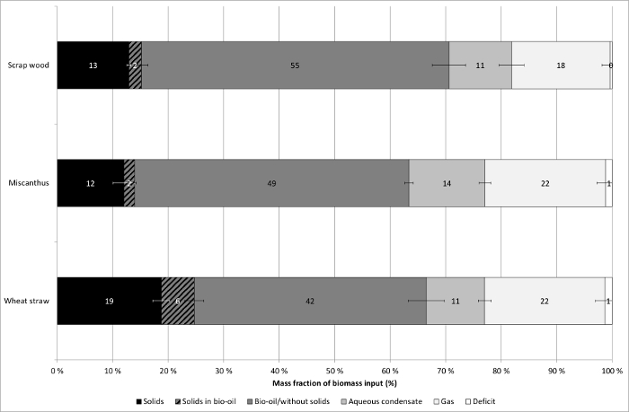
Figure 2. Mass balances of experiments. Balances are reported on an 'as received'21 basis of the feedstock and products. All values are expressed as mass fractions. Three different types of biomass have been used and all experiments were conducted at least in triplicates13. The solids content in the bio-oil is reported separately for illustration purposes. The error bars indicate standard deviations of experiments with one type of feedstock. Please click here to view a larger version of this figure.
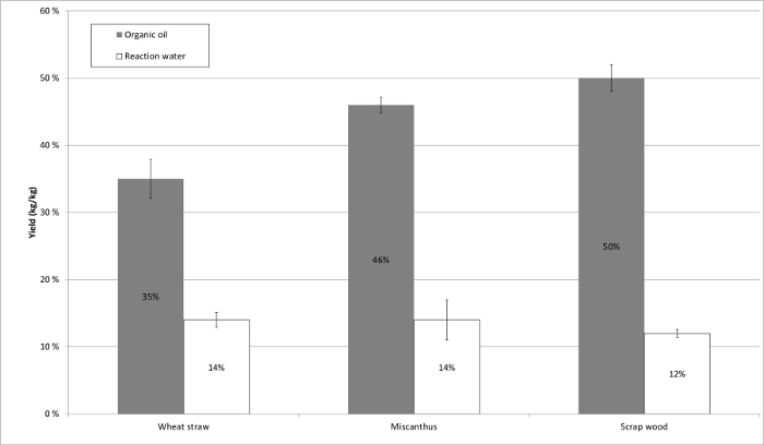
Figure 3. Total organic oil yields and water of reaction. All values are presented on a dry21 feed basis and are expressed as mass fractions. The solids content of the condensate has been excluded from the organic oil yield13. The error bars indicate standard deviations of experiments with one type of feedstock. Please click here to view a larger version of this figure.

Figure 4. Carbon balances. All values are reported as mass fractions of the biomass carbon input. Three different types of biomass have been used and all experiments were conducted at least in triplicates13. The solids content in the bio-oil is reported separately for illustration purposes. The error bars indicate standard deviations of experiments with one type of feedstock. Please click here to view a larger version of this figure.
Discussion
For all experiments, process conditions such as size of the feedstock material, feed rate, pressure, reaction temperature, condensation temperatures, and flow rates of both the heat carrier and the condensate cycle were the same. Naturally, variations within defined limits cannot be avoided. For a test plant such as the process development unit presented here, the acceptable ranges of fluctuation and required times of operation for reproducible experiments need to be calculated and/or determined by experience. For example, the reactor temperature, which is indicated by the temperature of the heat carrier leaving the reactor, is controlled with a standard deviation of 35 °C over the entire course of the reaction from the start of the reaction at full biomass capacity to the stop of biomass feeding (typically around 4 hr). The pressure in the reactor is controlled with a standard deviation of 300–500 Pa. Peaks in pressure are likely to occur due to fluctuations in biomass feeding. It is recommended to adjust the feeding screw system to the biomass material under consideration in order to minimize such fluctuations and ensure a constant biomass flow. The condensation temperature in the first and second condensers was maintained at a standard deviation of 3 °C and 1 °C, respectively.
It should be noted at this point that all experiments presented were conducted at the same reactor temperature (500 °C). This temperature does not necessarily reflect the optimum fast pyrolysis temperature which exists for each specific feedstock22. A variation of the reactor temperature could lead to an optimized pyrolysis temperature with even higher organic oil yields.
The choice of balancing method is not trivial for fast pyrolysis of biomass, especially when applying fractionated condensation and when using biomass with high ash content. Three different types of balancing have been presented in the previous section. Reporting the yields of product fractions on an 'as received' basis is advantageous for practical considerations such as the design of apparatuses and storage capacities as it reports the actual product distribution to be expected. However, these values are obscured by the water and ash contents of the feedstock. Especially for residual biomass — e.g., straw, forestry and pruning residues and biogenic 'waste' — this is an issue as these feedstocks have a wide range of water and inorganic contents, see Table 1.
The common balancing method for biomass processes on a 'dry basis' is in most cases useful for comparisons between different studies as it eliminates the effect of different moisture contents of the feedstock. However, it should be pointed out that these calculated values from experiments with a specific moist feedstock do not necessarily reflect the behavior and yields of this specific feedstock if it was completely dried by physical means prior to the experiment. It is known that moisture affects the yield distribution of pyrolysis23 and this should be kept in mind when evaluating and comparing 'dry' balances.
Furthermore, mass balances on a 'dry basis' are inappropriate for feedstocks with high ash content because minerals end up primarily in the char and obscure the results similarly to the initial moisture content. Similarly to water, minerals affect the actual pyrolysis reaction network because they promote secondary pyrolysis reactions, leading to higher char and lower bio-oil yields. Such effects can only be evaluated on a scientific basis if balances are corrected for the ash content. One way to achieve this is by setting up carbon balances. From the comparison of Figure 2 and Figure 4 it can be seen that the increased solids yield observed after pyrolysis of wheat straw as compared to miscanthus is not only due to inorganic material that is recovered with the char, but also due to an increased fraction of organic solids that were formed during the process.
Another advantage of elemental carbon balances is to show the fate of biogenic carbon, i.e., its distribution in the recovered product fractions. This is important for the evaluation of more complex conversion chains — e.g., pyrolysis, gasification, and synthesis as in the case presented here — because the biogenic carbon should be used as efficiently as possible. One of the most important roles of biomass in a future bio-based economy is to provide biogenic carbon for a wide range of commodities, thus replacing carbon from fossil resources.
The presented protocol for fast pyrolysis in a twin-screw mixing reactor can be realized on different scales with some adjustments. The presented case of a unit with a feed capacity of 10 kg hr-1 has proven to be a feasible compromise between operational complexity and meaningful results for process behavior. It can be applied both for screening of different types of biomass and optimization of process conditions. Testing a specific biomass feedstock is crucial because certain feedstock characteristics might lead to unfavorable process operation if coarse solid residues accumulate in the heat carrier cycle. Such accumulation was not observed for the biomass presented in the results section, but it has been observed for very hard biogenic material with large particle size (>1 mm) which limits the applicability of the presented process. This problem could be reduced with a different design of the heat carrier loop, e.g., by pneumatic transport of the heat carrier with simultaneous partial combustion.
Disclosures
The authors have nothing to disclose.
Acknowledgments
The authors thank Melanie Frank, Pia Griesheimer, Jessica Henrich, Petra Janke, Jessica Maier, and Norbert Sickinger for technical and analytical support of this work.
Financial support provided within the BioBoost project is greatly acknowledged. BioBoost is a European R&D project co-funded under contract 282873 within the Seventh Framework Programme by the European Commission (www.bioboost.eu).
Materials
| Name | Company | Catalog Number | Comments |
| Wheat straw | Dörrmann Kraichtal-Münzesheim | n/a | Triticum aestivum L. |
| Scrap wood | Rettenmeier Holding AG | n/a | According to class A2 of the German scrap wood decree (AltholzV §2): glued, coated, painted, or otherwise treated scrap wood without organic halogen compounds and wood preservatives |
| Miscanthus | Hotel-Heizungsbau Kraichgau-Odenwald | n/a | Miscanthus x giganteus |
| Ethylene glycol | Häffner GmbH & Co KG | 1042090220600 | |
| Ethanol | Häffner GmbH & Co KG | 1026800150600 | Grade 99.9% |
| Nitrogen | KIT | n/a | Supplied by internal nitrogen pressure system. |
| Pyrolysis test rig | self-built | n/a | Flow scheme is illustrated in manuscript. |
| Name | Company | Catalog Number | Comments |
| Analyses: | |||
| Gas chromatograph Daniel 700 | Emerson Process Management | n/a | Designed for this specific application by Emerson; two 20% SF 96 columns, two HAYESEP N columns, and one MS-5A washed column; carrier gas is helium |
| Helium | Air Liquide | P0252L50R2A001 | Grade 6.0 |
| Gas mixture for calibration | basi Schöberl GmbH & Co. KG | FG 10002 | Specified gas composition: 5% Ne, 2% O2, 20% CO, 30% CO2, 5% CH4, 5% H2, 2% C2H6, 0.5% C3H8, 0.5% C4H10, 0.5% C5H12, remainder N2. |
| Neon | Air Liquide | P0890S10R2A001 | Grade 4.0; used as fixed reference gas flow; not necessarily required and is only given as an example for quantifying the pyrolysis gas flow. |
| Elementaranalysator CHN628 | Leco Instrumente GmbH | 622-000-000 | |
| TGA701 | Leco Instrumente GmbH | n/a | |
| DIMATOC 2000 | Dimatec | n/a | |
| Hydranal methanol dry | Sigma Aldrich | 34741 | |
| Hydranal composite V | Sigma Aldrich | 34805 | |
| 841 Titrando | Deutsche Metrohm GmbH & Co. KG | 2.841.0010 | |
| 774 Oven Sample Processor | Deutsche Metrohm GmbH & Co. KG | 2.774.0010 | |
| 800 Dosino | Deutsche Metrohm GmbH & Co. KG | 2.800.0010 | |
| 801 Stirrer | Deutsche Metrohm GmbH & Co. KG | 2.801.0010 | |
| Methanol | Carl Roth GmbH & Co KG | 83884 | 99% for synthesis |
| Whatman cellulose filter grade 42 | Sigma Aldrich | WHA1442090 | |
| Methanol-D4 | Sigma Aldrich | 151947 | |
| 3-(Trimethylsilyl)propionic-2,2,3,3-d4 acid sodium salt | Sigma Aldrich | 269913 | |
| BZH 250 MHz | Bruker | n/a |
References
- Dahmen, N., Henrich, E., Dinjus, E., Weirich, F. The bioliq bioslurry gasification process for the production of biosynfuels, organic chemicals, and energy. Energ. Sust. Soc. 2 (1), 1-44 (2012).
- Ahmad, R., et al. Zeolite-based bifunctional catalysts for the single step synthesis of dimethyl ether from CO-rich synthesis gas. Fuel Process Technol. 121, 38-46 (2014).
- Haro, P., Trippe, F., Stahl, R., Henrich, E. Bio-syngas to gasoline and olefins via DME - A comprehensive techno-economic assessment. App Energy. , (2013).
- Henrich, E., Dahmen, N., Dinjus, E. Cost estimate for biosynfuel production via biosyncrude gasification. Biofuels, Bioprod. Bioref. 3, 28-41 (2009).
- Zhang, X., Kumar, A., Arnold, U., Sauer, J. Biomass-derived oxymethylene ethers as diesel additives: A thermodynamic analysis. Energ. Procedia. 61, 1921-1924 (2014).
- Bridgwater, A. V. Renewable fuels and chemicals by thermal processing of biomass. Chem. Eng. J. 91, 87-102 (2003).
- Meier, D., et al. State-of-the-art of fast pyrolysis in IEA bioenergy member countries. Renew. Sust. Energ. Rev. 20, 619-641 (2013).
- Rammler, R., Weiss, H. J., Bußmann, A., Simo, T. Gewinnung von Öl durch Schwelen von Ölschiefer und Teersand als Beitrag zur Energieversorgung. Chem. Ing. Tech. 53, 96-104 (1981).
- Tröger, N., et al. Utilization of biogenic residues and wastes in thermochemical systems for the production of fuels: current status of the project. Biofuels, Bioprod. Bioref. 7, 12-23 (2013).
- Tröger, N., Richter, D., Stahl, R. Effect of feedstock composition on product yields and energy recovery rates of fast pyrolysis products from different straw types. J. Anal. Appl. Pyr. 100, 158-165 (2013).
- Henrich, E., Dahmen, N., Weirich, F., Reimert, R., Kornmayer, C. Fast pyrolysis of lignocelluloses in a twin screw mixer reactor. Fuel Process Technol. 143, 151-161 (2016).
- Dahmen, N., et al. State of the art of the bioliq process for synthetic biofuels production. Env. Prog. Sust. Energ. 31, 176-181 (2012).
- Funke, A., et al. Fast pyrolysis char - Assessment of alternative uses within the bioliq concept. Bioresour. Technol. 200, 905-913 (2016).
- Lehto, J., Oasmaa, A., Solantausta, Y., Kytö, M., Chiaramonti, D. Fuel oil quality and combustion of fast pyrolysis bio-oils. , VTT Publications. Espoo. (2013).
- Fahmi, R., Bridgwater, A. V., Donnison, I., Yates, N., Jones, J. M. The effect of lignin and inorganic species in biomass on pyrolysis oil yields, quality and stability. Fuel. 87, 1230-1240 (2008).
- Oasmaa, A., Solantausta, Y., Arpiainen, V., Kuoppala, E., Sipilä, K. Fast Pyrolysis Bio-Oils from Wood and Agricultural Residues. Energ. & Fuels. 24, 1380-1388 (2010).
- DIN German Institute for Standardization. DIN EN ISO 18134-3 Solid biofuels - Determination of moisture content - Oven dry method - Part 3: Moisture in general analysis sample. , Beuth Verlag. Berlin. (2015).
- DIN German Institute for Standardization. DIN EN ISO 18122 Solid biofuels - Determination of ash content. , Beuth Verlag. Berlin. (2016).
- DIN German Institute for Standardization. Institute for Standardization. DIN EN ISO 16948 Solid biofuels - Determination of total content of carbon, hydrogen and nitrogen. , Beuth Verlag. Berlin. (2015).
- DIN German Institute for Standardization. Institute for Standardization. DIN EN 1484 Water analysis - Guidelines for the determination of total organic carbon (TOC) and dissolved organic carbon (DOC). , Beuth Verlag. Berlin. (1997).
- DIN German Institute for Standardization. ESO 16993: Solid biofuels - Conversion of analytical results from one basis to another. , Beuth Verlag. Berlin. (2015).
- Bridgwater, A. V. Review of fast pyrolysis of biomass and product upgrading). Biomass Bioenerg. 38, 68-94 (2012).
- Westerhof, R. J. M., Kuipers, N. J. M., Kersten, S. R. A., van Swaaij, W. P. M. Controlling the water content of biomass fast pyrolysis oil. Ind. Eng. Chem. Res. 46, 9238-9247 (2007).
