Ammonia can be synthesized at low pressure by using a conventional catalyst and an ammonia selective absorbent.
Ammonia can be synthesized at low pressure by the use of an ammonia selective absorbent. The process can be driven with wind energy, available locally in areas requiring ammonia for synthetic fertilizer. Such wind energy is often called "stranded," because it is only available far from population centers where it can be directly used.
In the proposed low pressure process, nitrogen is made from air using pressure swing absorption, and hydrogen is produced by electrolysis of water. While these gases can react at approximately 400 °C in the presence of a promoted conventional catalyst, the conversion is often limited by the reverse reaction, which makes this reaction only feasible at high pressures. This limitation can be removed by absorption on an ammine-like calcium or magnesium chloride. Such alkaline metal halides can effectively remove ammonia, thus suppressing the equilibrium constraints of the reaction. In the proposed absorption-enhanced ammonia synthesis process, the rate of reaction may then be controlled not by the chemical kinetics nor the absorption rates, but by the rate of the recycle of unreacted gases. The results compare favorably with ammonia made from a conventional small scale Haber-Bosch process.
Ammonia is a key industrial chemical. It is produced through the Haber-Bosch process, which is known as one of the most important innovations of the 20th century1,2. Ammonia synthesis is carried out in the presence of a heterogeneous catalyst at elevated temperatures (> 375 °C) and pressures (>100 bar)3. Such high temperature and pressure requirements make ammonia synthesis very energy- and capital-intensive. Approximately, 150 million tons of ammonia are produced each year4, which accounts for 1-3% of the world's energy consumption, 5% of the natural gas consumption, and up to 3% of the climate-changing gas emissions5,6,7.
Ammonia has two major potential uses. First, ammonia is a synthetic nitrogen fertilizer1. Without this fertilizer, half of the current population would not have access to sufficient food. Second, ammonia can serve as an energy vector, either as a carbon-neutral liquid fuel or as an indirect hydrogen carrier8,9,10,11. Typically, renewable resources (e.g. wind) are available in underpopulated rural areas, where it can be captured; this type of isolated wind and solar energy is called "stranded". In this scenario, the electrical and thermal energies from the renewable energy source are converted to energy-dense carbon-neutral liquid ammonia. The liquid ammonia produced can then be shipped to urban centers, where it can be directly used in ammonia-based fuel cells12 and internal combustion engines13, or it can be decomposed into hydrogen and then be used in hydrogen fuel cells or hydrogen stations. As a result, we can move the wind of the U.S. prairies to the crowded urban areas of the U.S.
Mostly because of the fertilizer use, ammonia manufacture is a major industry. At room temperature, the ammonia synthesis reaction is exothermic and hence—at least, in principle—spontaneous14, however, achieving the reaction under ambient conditions is extremely difficult because of the strong nitrogen-nitrogen bond15. To overcome this, Fritz Haber famously used high temperatures to achieve fast kinetics, but these high temperatures meant that the reverse reaction inhibited the production. To reduce the inhibitions of this reverse reaction, Haber used high pressure to improve conversion. He carried out the large-scale reaction in a gun barrel, which still decorates the BASF plant in Ludwigshafen.
The necessity to use both high temperature and pressure when the reaction could potentially run under much more modest conditions has frustrated chemists for over a century2. Even after the process was commercialized, Karl Bosch and a huge cohort at BASF churned through the entire periodic table looking for better catalysts. While Bosch had little success, the search still continues. Even last year, a new research program aimed at seeking a new catalyst was initiated16,17. The detailed chemistry of ammonia synthesis is now well understood14, and if the search for the new catalyst is successful, it would certainly be worth the effort. However, in our view, the past failures reduce the chance of future success.
In the following text, small-scale ammonia synthesis process is described, and the motivation to investigate an alternative process is explained.
The Small-Scale Process:
Wind-Generated Ammonia
We are improving the Haber-Bosch process for synthesizing ammonia, seeking a much smaller, simpler process which can be operated locally but produces negligible amounts of carbon dioxide. The feasibility of local ammonia manufacture from wind has already been demonstrated in a pilot plant located in Morris, MN, and shown in Figure 118. Morris sits on the Buffalo Ridge, a formation of sixty miles of rolling hills in the southwest corner of Minnesota. The ridge has unusually steady, strong wind, rolling across the prairie. As a result, it is a mecca for wind-generated electricity.
With this electricity, we already manufacture ammonia from wind, using this plant which is forty thousand times smaller than the existing commercial operations for fossil fuels. Some wind-generated electricity is used to make nitrogen from air by pressure swing adsorption, an established method for air separation used, for example, for patients with emphysema who need oxygen-enriched air. However, more of the electricity is used to make hydrogen by electrolysis of water. These gases are combined over a conventional catalyst in the process shown schematically in Figure 2. After the reaction, the gases are separated by chilling to condense the liquid ammonia. The unreacted gases, as well as the uncondensed ammonia, are recycled.
Details of the Pilot Plant
In our pilot plant, the University of Minnesota Renewable Hydrogen and Ammonia Pilot Plant, the electric power is provided from a co-located 1.65 MW wind turbine. The pilot plant uses approximately 10% of the power generated, with the remaining power used at the University of Minnesota, Morris campus.
The hydrogen production system uses an electrolyzer, a booster compressor, and a thermal chiller. This system produces 0.54 kg of hydrogen gas per hour, which is stored at 2,400 psi using 24 kWh of electricity. Water from an on-site well is purified using a reverse osmosis and deionization system. The water is then supplied to the electrolyzer at a rate of up to 15 L/h. Nitrogen is generated using a nitrogen generator, a pre-air compressor, an air dryer, and a booster compressor. The nitrogen gas is stored at 2,400 psi using approximately 6 kWh of electricity.
The synthesis of ammonia uses a custom skid. It includes a compressor, a reactor, a refrigeration cooling loop, and a 20 kW electric heater. The skid uses approximately 28 kWh of electricity to produce 2.7 kg of ammonia per hour which is then stored at 150 psi. The ammonia production process is controlled with integrated PLC and HMI systems. The produced hydrogen and nitrogen are stored on site in 18 nitrogen storage tanks and 54 hydrogen storage tanks. The ammonia is also stored onsite within a 3,100-gallon vessel.
Wind Generation is Expensive
The electricity for this process is made from wind, and so the fuel for making ammonia is free, without using any fossil fuel. However, the capital costs for this pilot plant are dominated by the investments for hydrogen production and for ammonia synthesis. The operations to date suggest that the cost of making small-scale ammonia are about twice that of conventional ammonia based on fossil fuels. While we continue to optimize our process, we believe that small-scale wind generated ammonia will not be competitive at the current natural gas prices. The capital costs per mass ammonia made could be reduced by a larger conventional process, or by an alternative process like that described next in this paper.
The Absorption Process:
Absorption Enhances Production
The catalyst used for ammonia synthesis has remained almost unchanged during the last century19. As a result, we have carried out a different approach in this research. We apply the current catalyst and operating temperature, but absorb ammonia at modest pressures as soon as it is formed. We recycle any unreacted hydrogen and nitrogen. The process is schematically like that in Figure 3, similar to the conventional process, but with a packed bed absorber replacing the condenser.
Initial Reaction Kinetics Do Not Change
Experiments with this system at low conversion show an initial reaction rate that is consistent with many of the earlier studies on this system3,14,15,20,21,22,23, as shown in Figure 4. The left panel shows the initial rates, which vary strongly with temperature. While these rates also vary with pressure, the variations are smaller, as shown in the right panel. In our new process, we use the same catalyst and similar operating conditions, but seek ways to improve ammonia production by using absorption at a lower pressure. We thus hope to reduce the capital costs for ammonia synthesis.
Absorption Enhances Conversion
In our work, we replaced the condenser in the small process with a packed bed, which is a cylindrical vessel filled with small particles of the absorbent. We have emphasized absorbents made primarily of magnesium chloride and calcium chloride11,24. Such ammine absorbents have two effects. First, they reduce the ammonia concentration present in the recycled gases to near zero. Second, they effectively reduce the time for separation to near zero. This strategy is productive25,26,27. For example, in Figure 5, we show that the rate of making ammonia, which is proportional to the drop in the total pressure in the system, is much greater with absorption than without. In particular, the reaction at 90 bar, shown by the red circles, is less complete than the reaction with the absorbent, shown by the blue triangles27. This is true even though the reaction without absorbent takes place at a pressure almost twice that of the reaction with absorption. In earlier experiments (not shown here), we also showed that the eventual conversion of the process is about 20% without absorbent but over 95% with absorbent.
The rate of reaction varies much less with temperature with absorption than without. This is shown in Figure 6, which again reports ammonia synthesis as total pressure versus time27. Changing the reaction temperature by 60 °C has little effect on the reaction rate. This contrasts with the initial rates in Figure 4, which shows a change of reaction rate of almost an order of magnitude. The results in Figure 4 and Figure 6 are different because the effect of the reverse reaction has been reduced, so the chemical kinetics are no longer the only step responsible for the overall rate.
1. Pilot Plant Start-up
2. Experimental Apparatus Start-up
A pilot plant in Morris, MN has demonstrated the feasibility of using wind for local ammonia manufacture18, as shown in Figure 1. The wind generates electricity, which is used to make nitrogen and hydrogen through the pressure swing absorption of air and through the electrolysis of water, respectively. A reactor uses a conventional catalyst to combine the nitrogen and hydrogen gases, making ammonia. The ammonia is then separated using a condenser.
The method described here includes a process to recycle any unreacted hydrogen and nitrogen. The overall procedure is similar to that demonstrated in Figure 3, the conventional process, except the condenser is replaced with a packed bed absorber. The absorbents are primarily made with magnesium chloride and calcium chloride. The initial reaction rates demonstrated by this system at low conversion are consistent with many earlier studies, as demonstrated in Figure 4. The total pressure drop in the system is proportional to the ammonia production rate. This rate is much greater with absorption than without, as illustrated in Figure 5. Also, with absorption, the rate of reaction varies much less with temperature (Figure 6). With absorption, a temperature change of 60 °C has little effect on the reaction rate, while the initial reaction rates (Figure 4) demonstrate almost an order of magnitude change.
At the temperatures and pressures used here, pure ammines are not stable. At a given flow, the amount of ammonia absorbed by the bed is reduced after its repeated use (Figure 7). Stabilizing the absorbent can improve its capacity. As demonstrated in Figure 8, this stability over many cycles can be achieved by trapping small magnesium chloride crystals in fissures of the alumina. Additional improvements to the absorbent are currently being investigated.
With absorption, chemical and absorption kinetics are less able to limit ammonia production, as illustrated in Figure 9. The intercept at infinite pump flow includes the resistances of reaction and absorption. When this reciprocal is small, the chemical reaction values are large. Higher pump flows correspond to rate increases; at infinite pump flow, the rate can be extrapolated to a finite limit.
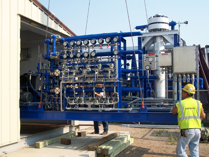
Figure 1. The Small-scale Plant. Please click here to view a larger version of this figure.
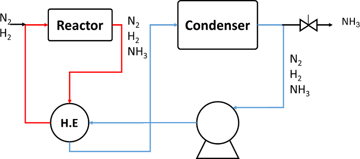
Figure 2. A Schematic Drawing of the Small-scale Plant. Please click here to view a larger version of this figure.
Figure 3. The Absorbent Process. Please click here to view a larger version of this figure.
Figure 4. Initial Reaction Rates. Please click here to view a larger version of this figure.
Figure 5. Conversion Without and With Separation by Absorption. Please click here to view a larger version of this figure.
Figure 6. Reaction with Absorption. Please click here to view a larger version of this figure.
Figure 7. Current Absorbents are Limited. Please click here to view a larger version of this figure.
Figure 8. Micrographs of Absorbents. Please click here to view a larger version of this figure.
Figure 9. Reaction versus Recycle Flow. Please click here to view a larger version of this figure.
Peak Temperature Range (°C) | Max. Rate of Temperature Increase (°C/h) | Time in Heating Steps (h) | Time (h) |
Ambient-340 | 40 | 8 | 8 |
340-370 | 15-20 | 2 | 10 |
370-400 | 10-May | 5 | 15 |
400-430 | 0-5 | 28 | 43 |
430-470 | 5 | 8 | 51 |
Hold Inlet Temperature at 450 (°C) for 4 h |
Table 1. Temperature Ramps Used to Activate the Catalyst.
7/14/2014 | 9/2/2014 | 9/17/2014 | 10/29/2014 | 1/9/2015 | |
Reactor T | 569 | 575 | 563 | 565 | 557 |
Pressure p | 112 | 72 | 124 | 117 | 128 |
Condenser T | 404 | 365 | 425 | 413 | 420 |
Reaction | 9 | 3 | 17 | 14 | 30 |
Condensation | 0.019 | 0.012 | 0.021 | 0.02 | 0.022 |
Recycle | 0.004 | 0.005 | 0.004 | 0.003 | 0.003 |
Table 2. Typical Rate Data from Pilot Plant Operation.
The times for reaction, condensation, and recycle show that the chemical kinetics has the largest time, and hence the slowest rate. Units: T (°C), p (bar)
Critical Steps of the Reaction-absorption Experimental Apparatus:
Make sure that there is no impurity in the nitrogen and hydrogen system. The absorbent materials will change after each cycle. In most cases, at high temperature and in the presence of ammonia, the absorbent materials fuse and form a large solid concrete. According to the thermodynamic properties of each metal halide and ammine complex, the appropriate temperatures for absorption and desorption should be employed. Before each test, the pressure drop across the system (absorber, reactor, tubing, valves, fittings, etc.) should be checked, to make sure that the recirculation loop, absorber, or reactor are not imposing large pressure drops across the system.
Limitations: The Best Absorbents Known Now Are Unstable:
The ammine absorbents used to separate ammonia have a large potential capacity, as much as six moles of ammonia per mole of calcium. This absorption is controlled by the diffusion in the solid, and hence is much slower than diffusion in the surrounding gases. Absorption at the high temperatures and pressures like those in the synthesis reactor has a smaller capacity, but is still usually more than the amount collected by surface adsorption.
However, the absorbents themselves, especially magnesium chloride, are not stable28. As a result, breakthrough curves in packed bed experiments are not reproducible, as shown in Figure 7. This figure reports the breakthrough curves of ammonia-nitrogen mixtures flowing through a packed bed of particles of magnesium chloride. As expected, the bed does absorb the ammonia, but the amount absorbed at a given flow drops as the bed is repeatedly used. At the same time, the solids in the bed change from a free-flowing powder to a single concrete mass. This fusion makes the kinetics of absorption much slower. To overcome this, we made a packed bed of alumina supporting the small crystals of magnesium chloride. Such a bed does show stable breakthrough curves, apparently stabilized by the small chloride crystals trapped within fissures of the alumina and shown in Figure 828. Further improvement in the absorbent remains an active research focus.
Significance of the Method: Recycle of Unreacted Gas Now Controls:
The controlling step is now, largely, the rate of recycle of the unreacted gases, as shown in Figure 9. This figure plots the reciprocal of the pressure change versus the reciprocal of the pump flow. The pressure change is, of course, the same measure of reaction that we used in Figure 5 and Figure 6: the small values of this reciprocal correspond to the large values of the chemical reaction. The reciprocal of the pump flow, shown on the x-axis, is simply a convenient way to investigate what happens as the pump flows approach infinity. As can be seen, the rate increases at higher pump flows, and extrapolates to a finite limit at infinite pump flow. This limit is close to the fastest reaction rate possible, that is, the forward reaction rate without the constraints of either the reverse reaction or separation. The slope on this line measures the effect of recycling the unreacted gases.
The results shown above confirm the viability of the reaction absorption process for the enhanced production of ammonia at significantly lower pressures. For example, in one set of measurements, we obtained more than 80% conversion with relative fast ammonia synthesis rates. This suggests that high production rates at pressures as low as 25 bar are viable when ammonia is removed from the system efficiently. The absorption separates the synthesized ammonia from the reaction environment and induces the reverse reaction.
The data for the current pilot plant and for our absorption studies show that the reaction rate for moles ammonia synthesized per time equals the ammonia concentration in the system at equilibrium minus the true ammonia concentration, divided by three characteristic times. The first of these times is the time of reaction, the second is the time of separation, and the third is the time for recycle. Examples of these times are shown in Table 1, where the absorption step is by partial ammonia concentration. At present, the time of reaction is the largest, so that the existing pilot plant's productivity is controlled by the chemical reaction rate. We can increase the reaction rate by increasing the temperature. We are doing this, and the plant is running well.
Future Applications and Directions:
The data for both the pilot process and the absorption process can also be analyzed in terms of a concentration difference divided by three characteristic times. More specifically,
where C and C* are the nitrogen concentrations actually present and present at equilibrium, respectively, and τrxn, τsep, and τrecycle are times of reaction, separation, and recycle, respectively. In the small plant and in our initial rate measurements, the time of reaction is the largest, that is, the slowest. It controls the overall rate. Therefore, we are trying to run the pilot plant at higher temperatures.
However, in our absorption process, the concentration at equilibrium C* is near zero because of absorption. Also, the times of reaction and absorption in an unsaturated bed are somewhat smaller than the time of recycle. Thus, the plot of inverse reaction rate versus the reciprocal of recycle flow should give a straight line roughly like that in Figure 9. The slope on this line should correspond to the recycle flow, and the intercept will represent any contributions of the chemical rates and absorption rates. Our preliminary data support this prediction, and suggest ways in which our synthesis can be further improved.
While these results are preliminary, they still permit speculation about the design of a small, efficient process that manufactures ammonia at reduced pressure. This obviously depends on an efficient absorbent. In the experiments to date, we have not focused on the rate of uptake of the absorbent and hence on its physical geometry. We have found this geometry is not always stable under reactor conditions, and hence represents a major area for continued development. We also have not worried about the amount of absorbent required: to get more absorption, we simply have used more absorbent. In addition, we have not worried about the absorbent lifetime; we have noted absorbent properties frequently deteriorate with use, both by forming fines and by apparently showing reduced surface area. All of these issues, dealing both with the absorbent and with the absorber design, must be resolved to further clarify the potential of this process. At the moment, however, the prognosis is good.
The authors have nothing to disclose.
This work was primarily supported by ARPA-E, a part of the US Department of Energy, by the Minnesota Environment and Natural Resources Trust Fund, as recommended the Legislative-Citizen Commission on Minnesota Resources, and by MNDRIVE, an initiative of the University of Minnesota. Additional support came from the Dreyfus Foundation.
Experimental Apparatus | |||
Magnesium Chloride | Sigma Aldrich | 7786-30-3 | St. Louis, MO |
Calcium Chloride | Sigma Aldrich | 10043-52-4 | St. Louis, MO |
Ultra Pure Hydrogen | Matheson | SG PHYF30050 | New Brighton, MN |
Ultra Pure Nitrogen | Matheson | SG G1881112 | New Brighton, MN |
Iron Based Catalyst | Clariant/Sud Chemie | – | Charlotte, NC |
Variable Piston Pump | PumpWorks Inc. | PW2070N | Minneapolis, MN |
Omega Ceramic Heater | Omega | CRFC-36/115-A | Stamford, CT |
PID Controller | Omega | CN96211TR | Stamford, CT |
Signal Conditioner | Omega | DRG-SC-TC | Stamford, CT |
Pressure Transducer | WIKA | 50426877 | Lawrenceville, Georgia |
Mass Flow Controller | Brooks Instruments | SLA5850 | Hatefield, PA |
Name | Company | Catalog Number | Comments |
Pilot Plant | |||
Electrolyzer | Proton OnSite | H6 Series | Wallingford, CT |
Gas Booster | PDC Machine | 3 2500 | Warminster, PA |
Wind Turbine | Vestas | V82 | Portland, OR |
Chiller | Thermal Care | SQ Series | Niles, IL |
Water Purifier | Elga Pure Lab | S-15 | |
Nitrogen Generator | Innovative Gas System | NS-10 | Huoston, TX |
Air Compressor | Hydrovane | HV05 |