Delignified densified wood represents a new promising lightweight, high-performance and bio-based material with great potential to partially substitute natural fiber reinforced- or glass fiber reinforced composites in the future. We here present two versatile fabrication routes and demonstrate the possibility to create complex composite parts.
Method Article
Fabrication and Design of Wood-Based High-Performance Composites
In This Article
Summary
Abstract
Delignified densified wood is a new promising and sustainable material that possesses the potential to replace synthetic materials, such as glass fiber reinforced composites, due to its excellent mechanical properties. Delignified wood, however, is rather fragile in a wet state, which makes handling and shaping challenging. Here we present two fabrication processes, closed-mold densification and vacuum densification, to produce high-performance cellulose composites based on delignified wood, including an assessment of their advantages and limitations. Further, we suggest strategies for how the composites can be re-used or decomposed at the end-of-life cycle. Closed-mold densification has the advantage that no elaborate lab equipment is needed. Simple screw clamps or a press can be used for densification. We recommend this method for small parts with simple geometries and large radii of curvature. Vacuum densification in an open-mold process is suitable for larger objects and complex geometries, including small radii of curvature. Compared to the closed-mold process, the open-mold vacuum approach only needs the manufacture of a single mold cavity.
Introduction
The development of novel natural fiber (NF) based composites equipped with superior mechanical properties represents one of the main tasks in materials science, as they can be sustainable alternatives for current synthetic systems such as glass fiber composites1,2,3. Besides traditional NF composites (flax, hemp, kenaf, etc)4,5, the densification of wood after partial or complete removal of matrix components has received increasing attention in recent years6,7,8,9,10,11. The top-down fabrication route, based on delignification of bulk wood followed by densification, is conceptually contrary to rather complex bottom-up processes for pulp and slurry based products12. In pulp and slurry based products, the beneficial wood fiber alignment is not retained as fibers are separated in the process. In contrast, structure-retaining delignified wood, which is obtained in a top-down process, transfers the sophisticated architecture with aligned cellulose fibers into the new material. To achieve densification of delignified wood without fiber alignment distortions, new processing routes must be developed.
Direct densification of water-saturated delignified wood samples leads to a limited densification degree, cracks, and fiber alignment distortions due to the wet-sample-inherent free water that creates a counter pressure during densification. Current solutions to avoid structural integrity loss upon densification includes utilization of partially delignified wood followed by high-temperature densification9 or pre-drying of delignified wood prior densification6. Both methods enhance connectivity between neighboring cells, either due to the remaining lignin that acts as glue or free water removal between cells.
In both cases, reduced formability occurs, which limits design applications; the required sample pre-conditioning also leads to longer processing times. Therefore, a fast and scalable process that combines shaping and densification in a single step is necessary.
In this regard, we present here open/closed-mold densification and vacuum processing of delignified wood as methods to combine shaping, densification, and drying in a simple and scalable approach. Figure 1 shows delignified densified wood-composite parts, which were obtained by using the techniques described in this work.

Figure 1: Examples of delignified densified wood composite parts. (A) Door panel, (B) side mirror, (C) door handle of a car, (D) orthosis, (E) cut open helmet, and (F) tachometer cover of a car. Please click here to view a larger version of this figure.
Protocol
1. Delignification of wood veneers
NOTE: This delignification protocol is based on our previous works, published by Frey et al. 20186 and Segmehl et al. 201813.
- Mount a stainless-steel sample holder in a crystallizing dish or in a beaker and place a magnetic stir bar below the sample holder. Stack wood veneers on top of the holder and separate them by metal meshes or metal mesh stripes (Figure 2A). Here, we use radial cut spruce veneers with a thickness of 1.5 mm. Wood species and type (tangential, radial, rotary cut veneer) as well as the thickness of veneers can be varied.
- Prepare a 1:1 volume mixture of hydrogen peroxide (30 wt%) and glacial acetic acid and pour the mixture into the crystallizing dish until the veneers are fully covered. Use glass dishes (e.g. Petri dish) to keep the veneers in the solution. Soak samples in the solution at room temperature (RT) overnight while stirring at 150 rpm.
- Heat the solution to 80 ˚C and run the reaction for 6 h for full delignification. Adjust the delignification time depending on the sample thickness.
- After delignification, pour the delignification solution into an empty beaker and let it cool down before disposal. Gently rinse the delignified veneers multiple times with deionized water. Then, continue washing the veneers without stirring by filling the crystallizing dish (beaker) with deionized water. Replace the water twice a day until a pH value of the washing water of above 5 is reached (Figure 2B).
- Handle wet delignified wood veneers with care, as the cellulose scaffold is rather fragile. Use a metal mesh as support for transportation and draping (Figure 4).
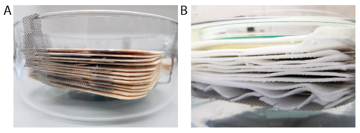
Figure 2: Delignification setup. (A) Crystallizing dish with metal mesh sample holder and wood veneers stacked on top of the sample holder. Metal mesh stripes separate the individual veneers from each other. (B) Delignfied veneers covered by water during the washing process. Please click here to view a larger version of this figure.
2. Storage and "cellulose prepreg" production
- Consider processing the wet delignified wood samples within 2-3 weeks. Alternatively, preserve the material for long-term storage in ethanol (EtOH) or dry the sheets between metal meshes.
- Store the dry, flat cellulose sheets ("cellulose prepregs") below 65% relative humidity (RH). Rewet the sheets in water prior to further shaping and processing.
3. Densification and forming of delignified wood in closed molds
- Use closed molds made out of an open-porous material (e.g. ceramic molds, porous 3D printed polymer molds) to enable water removal and sufficient drying. Pore sizes should be below 2 mm, especially towards the surface, to obtain a smooth surface of the final composite part.
- Condition the delignified wood at desired RH. For curvature radii in the cm range or plane structures, use samples that are conditioned at 95% RH at 20 ˚C. For smaller curvature radii, drape the veneer in water-saturated state, pre-dry the draped material in an open mold at 95% RH, or pre-dry the material in an oven (65 ˚C) for 5-30 min (the time is depends on the sample thickness). Curvature considerations are made in relation to veneer thickness (here 1.5 mm).
- Densify the material in the closed mold either by using screw clamps or in a press. Readjust the pressure if needed to compensate for shrinkage. The drying process can be speed up by placing the mold into an oven at 65 ˚C or by increasing the temperature of the press.
NOTE: A relatively low pressure in the range of a few MPa is sufficient to densify wet delignified wood. The final thickness can be controlled by using spacers with the targeted thickness between the mold surfaces rather than by controlling the pressure. - After full drying, demold the composite part and reuse the mold for a new run.
4. Vacuum shaping and densification of delignified wood in open molds
- Use a porous open mold as described in 3.1. Alternatively, use non-porous molds with a porous layer (e.g. mesh, textile, breather) on top of the mold or on top of the delignified wood to enable drying (Figure 3A).
- Use a textile layer (e.g. peel-ply) to protect the mold from contamination. Drape a water-saturated delignified veneer on top of the textile (Figure 3B) and cover it with a second textile layer and flow mesh.
NOTE: To obtain a smooth surface finish, we recommend using porous closed-mold processing. For this, replace the flow mesh with the porous top part of the mold. However, if surface patterning with e.g. a mesh is desired, the open-mold process is a good alternative. - Place the mold on top of a stainless-steel plate, apply sealing tape and vacuum tubing, and wrap the mold (open or closed) with a vacuum bag. Use flow mesh to enable water flow to the vacuum tubing. Optionally, place additional mesh layers below the mold to enhance the drying process and to avoid local vacuum pressure drops, especially for bigger parts (Figure 3C).
- Apply a vacuum for drying and simultaneous densification of the composite. For accelerated drying, place the setup into an oven at elevated temperature (e.g. 65 ˚C).
NOTE: Make sure to use cold traps to avoid water entering the vacuum pump. We here use an oil pump in a pressure range of 10-2 bar. However, it is also possible to use a membrane pump but trade-offs regarding densification degree might need to be taken into account. - After drying, demold the dry composite and reuse the mold and vacuum setup for a new composite part (Figure 3D).

Figure 3: Schematic illustration of the open-mold process. (A) Porous mold with smaller pores towards the surface. (B) Delignified wood draped on top of the porous mold (grey) and optional textile layer for mold protection (green). (C) Textile, flow mesh and vacuum bag placed on top of delignified wood. Pressure is applied through the vacuum bag and leads to densification and drying of the material. (D) Final composite after demolding. Please click here to view a larger version of this figure.
5. Manufacturing of laminated composite parts
- Manufacture thick multi-layer composite parts by lay-up techniques and choose the fiber orientation angle of the layers (e.g. [0˚], [0˚/90˚], [0˚/-45˚/90˚/+45˚]S) as in traditional composite manufacturing.
NOTE: The number of layers can be chosen depending on the targeted thickness of the final part. However, the vacuum time strongly depends on the size and thickness of the part and ranges from 2 h (single layer, 1.5 mm thick) up to 2 days for an 8-ply part. - Increase bonding between delignified wood layers by applying adhesive between layers during the draping process. Use a water based adhesive (e.g. starch) which allows combined drying and curing of the adhesive.
NOTE: We apply 0.04 g/cm2 of a 16.5 wt% starch solution between the layers. However, other water-based glues could be used alternatively. - Demold the composite part and machine finish by hand or with standard wood tooling (Figure 6E,F).
6. Re-use and recycling of composite parts
- Place delignified non-glued wood composites in water until the part regains formability. Then, either reshape the material to obtain a new product (see Frey et al. 20197) or reduce it to small pieces.
- Reuse the small pieces of delignified wood to create new products inspired by standard pulp techniques (e.g. pulp molding) and finally let the material biodegrade after end of life.
Results
Delignification and handling of wood veneers.
Complete delignification leads to a mass reduction of around 40% and a volume reduction of around 20% after drying at 65% RH6. Besides lignin, a fraction of hemicelluloses gets removed too. Removal of these components results in a fragile cellulose material (see Figure 4). Using metal meshes as supports eases handling and draping.
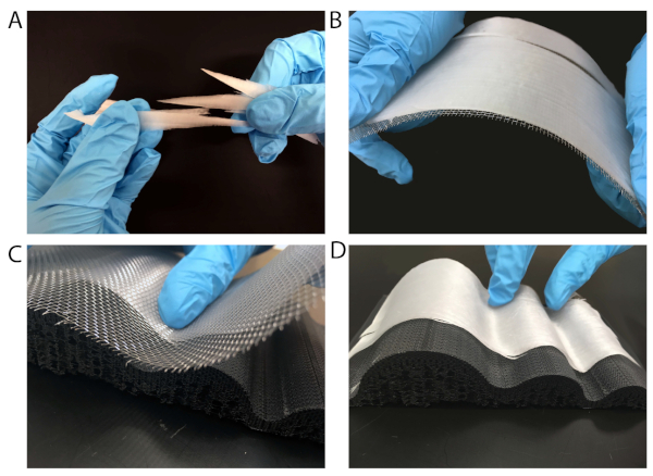
Figure 4: Handling of delignified wood in wet state. (A) Fragile delignified wood in its wet state. (B) Handling of the material is eased by using a metal mesh for transportation or (C) for draping the material to a mold. (D) Delignified wood draped on top of a porous 3D-printed mold. Please click here to view a larger version of this figure.
Densification and forming of delignified wood in closed molds.
Densification of water-saturated delignified wood (Figure 5A-C) is demanding, as free water in the scaffold creates a counter pressure upon densification and allows the material to flow during processing. This causes fiber deviations and cracks in the final material (Figure 5B,C). One possibility to bypass these limitations is to use moist pre-conditioned (95% RH and 20 ˚C), delignified wood. In this condition, delignified wood is still reasonably shapeable and its densification does not lead to fiber alignment distortions and defects.
Pre-conditioned material, however, is more rigid compared to the water-saturated state, which makes it difficult to obtain small curvature radii without material damage. For small curvature radii, wet draping followed by conditioning in an already shaped state prior densification can be used. However, conditioning is rather time consuming and therefore not recommended for large-scale applications.
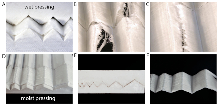
Figure 5: Closed-mold densification of delignified wood in a wet and moist state. (A) Densification of the water-saturated cellulose material leads to (B,C) cracks and fiber misalignment. (D-F) Densification of moist material, conditioned at 95% RH results in a better preservation of fiber alignment and less defects. Please click here to view a larger version of this figure.
Vacuum shaping and densification of a laminated part in an open mold.
Exemplarily for vacuum shaping, we manufactured a helmet in a self-made gypsum mold using an open-mold process (Figure 6A,B). As lay-up, we draped 2 layers of hexagon-flakes for surface texturing followed by 4 layers of delignified wood veneer in a [0˚/90˚] lay-up (Figure 6C). The flakes provide an attractive surface design, whereas the unidimensional (UD) layers add strength and stiffness to the composite. We applied 16.5 wt% starch as adhesive between layers to prevent delamination14.
Vacuum densification (Figure 6D) leads to full drying of the part within 48 h and densification down to a thickness of 3 mm (1/3rd of the initial thickness). After the vacuum processing, the composite part is demolded (Figure 6E) and the edges are trimmed with a cutter (Figure 6F).
The maximum layup thickness that could be densified and fully dried with the open-molding approach was an 8-layer layup (8 x 1.5 mm veneer) with an end thickness of this part of 2.5 mm, which corresponds to a densification down to approximately one quarter of the initial thickness of dry delignified wood, taking into account the layer shrinkage upon delignification and drying. To obtain such high densification degrees, a low vacuum in the range of 10-2 bar is needed.
Delignified wood composites that are densified to around one quarter of their initial thickness typically achieve elastic moduli values around 25 GPa and strength values in the range of 150-180 MPa, as shown in our previous work (Table 1)7.

Table 1: Literature values for tensile elastic modulus and tensile strength of densified delignified wood. The vacuum processing results in a densification down to 1/4th of the initial thickness, which corresponds to an FVC of 66%.
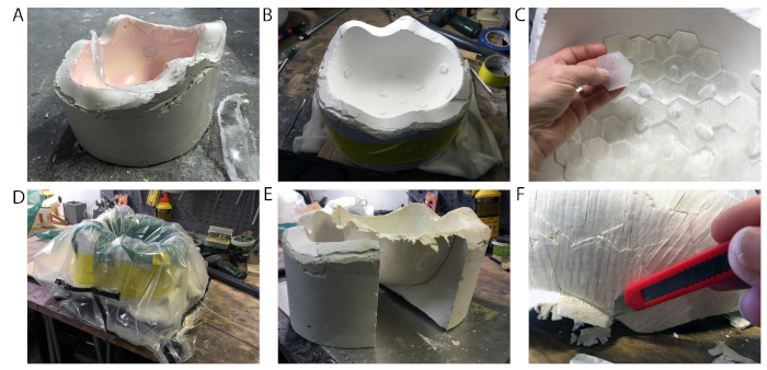
Figure 6: Manufacturing of a helmet by open-mold processing. (A,B) Molding of the original helmet using a gypsum mold. (C) Draping of two outer layers with hexagon flakes followed by draping the inner 4-layers in a [0/90] layup. (D) Densification and drying of the part by vacuum. (E) Demolding of the dry part and (F) finish using a cutter. Please click here to view a larger version of this figure.
Utilizing flow meshes typically results in a mesh-imprint in the sample. This can either be considered as a process-inherent design strategy or can be prevented by placing an additional thicker textile layer between delignified wood and flow mesh.
Alternatively, closed molds combined with vacuum processing as described in protocol step 4.2 can be used. Regular patterning can be obtained by placing small pieces of delignified veneers in a defined order, as shown before for our example with the hexagon patterning on the helmet.
Problems that can arise during vacuum processing include warpages in the composite part, which are caused by incomplete drying and the occurrence of cracks (Figure 7). Cracks mainly result in delignified wood that was stored in EtOH prior composite fabrication. Therefore, after EtOH storage, we recommend to carefully soak delignified wood in water before further processing. Additionally, careful draping followed by slight densification by hand to remove some free water reduces the risk of cracking.
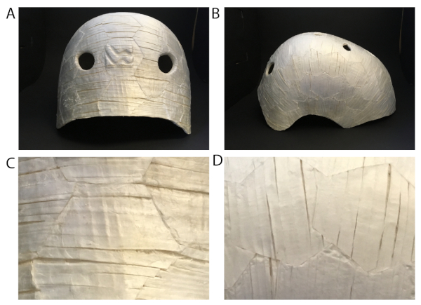
Figure 7: Possible problems arising in fabrication of complex geometries. (A) Back view and (B) side view of the manufactured helmet. (C,D) Small cracks due to shrinkage of the material during processing. Please click here to view a larger version of this figure.
Re-use or decomposition of composite parts.
Our cellulose-starch composite is all bio-based and can disintegrate in water. On the one hand, the hydrophilicity of the material is a disadvantage, as it leads to reduced mechanical performance when in contact with water. A simple method to protect the composite from liquid water comprises hydrophobic coatings, as we have shown in Frey et al. 20197. On the other hand, a hydrophilic behavior of the material can also be beneficial when it comes to end-of life use and recycling aspects. The sample can simply be disintegrated in water to smaller pieces and the fibrous slurry can further be used for the production of new fiber-based products as shown in Figure 8. Furthermore, the fibrous material is fully biodegradable, as shown in Figure 9.
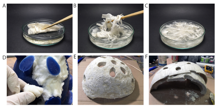
Figure 8: Re-use of delignified wood fibers. (A-C) Reduction of delignified wood veneers into small pieces by dispersing the material in water. (D-F) Re-use of the fiber slurry for producing the lining of a helmet. (D) Reveting of a silicon mold with fiber slurry. (E) Final lining of the helmet. (F) Lining made out of disintegrated delignified wood inside of the hard shell of the helmet. Please click here to view a larger version of this figure.
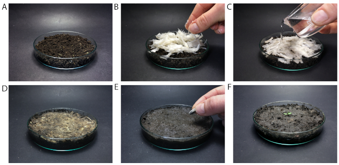
Figure 9: Degradation of delignified wood fibers. (A) Petri dish filled with soil. (B) Placing the fiber slurry on top of the soil and (C) filling it with water. (D) Bio-degradation after one day, (E) after eight days, and (F) after 26 days. Please click here to view a larger version of this figure.
Discussion
We present versatile fabrication techniques to obtain high-performance delignified wood-based composites and suggest possible re-use and recycling strategies. Closed-mold processing prerequisites pre-conditioning of the material, as it cannot be processed in water-saturated state. Utilizing a closed-mold process, however, could be the method of choice especially if e.g. there is no vacuum setup available or if a nice (smooth) surface finish on both sides is desired.
Open-mold vacuum processing of delignified wood allows for combining shaping, densification, and drying of water-saturated samples in a simple and scalable approach. The technique is applicable for the production of complex geometries and offers a scalable alternative for closed-mold processes. We have manufactured composites by stacking delignified wood veneers using starch as adhesive between layers. Densification down to one quarter of the initial thickness resulted in a final thickness of 2.5 mm of the 8-layer thick composite part. For obtaining a smoother surface finish in the vacuum process, the use of a closed porous mold could be an appropriate alternative.
For both processing methods, we recommend the use of an adhesive system in between delignified wood layers in order to decrease the risk of delamination. For the given example, we choose starch, as it is a well-known bio-based glue for pulp and paper products, such as paper bags, and is water based. Future works will focus on the fabrication of thicker laminates to resolve current limitations in terms of drying and fiber flow deviations.
In general, vacuum processing of delignified wood has the potential for an easy and fast production of large-scale densified cellulose fiber composites. After addressing the material's durability issue by applying proper coatings, water-stable adhesive systems or chemical modification, possible industrial applications may include automotive components such as door panels, floors, and dashboards. Our material could replace metals or fiber reinforced composites in order to reduce weight for better fuel efficiency and to improve recyclability.
Disclosures
The authors have nothing to disclose.
Acknowledgements
The authors thank Silvan Gantenbein for the 3D printing of porous molds.
Materials
| Name | Company | Catalog Number | Comments |
|---|---|---|---|
| Acetic acid | VWR Chemicals | 20104.312 | |
| Breather | Suter Kunststoffe AG | 923.015 | |
| Flow mesh/bleeder | Suter Kunststoffe AG | 180.007 | |
| Gypsum | Suter Kunststoffe AG | 115.3002 | |
| Hydrogen peroxide, 30% | VWR Chemicals | 23622.298 | |
| Oven | Binder GmbH | ||
| Press | Imex Technik AG | ||
| Seal tape | Suter Kunststoffe AG | 31344 | |
| Stainless steel mesh | Drawag AG | ||
| Starch | Agrana Beteilungs AG | ||
| Textile, peel ply | Suter Kunststoffe AG | 222.001 | |
| Vacuum bag | Suter Kunststoffe AG | 215.15 | |
| Vacuum bag, elastic | Suter Kunststoffe AG | 390.1761 | elastic vacuum bag for complex shapes |
| Vacuum pump | Vacuumbrand | ||
| Vacuum tubing | Suter Kunststoffe AG | 77008.001 | |
| Wood veneers | Bollinger AG |
References
- Joshi, S. V., Drzal, L. T., Mohanty, A. K., Arora, S. Are natural fiber composites environmentally superior to glass fiber reinforced composites? Composites Part A: Applied Science and Manufacturing. 35 (3), 371-376 (2004).
- Mohanty, A. K., Misra, M., Drzal, L. T. Sustainable Bio-Composites from Renewable Resources: Opportunities and Challenges in the Green Materials World. Journal of Polymers and the Environment. 10 (1), 19-26 (2002).
- Mohanty, A. K., Vivekanandhan, S., Pin, J. M., Misra, M. Composites from renewable and sustainable resources: Challenges and innovations. Science. 362 (6414), 536-542 (2018).
- Pickering, K. L., Efendy, M. G. A., Le, T. M. A review of recent developments in natural fibre composites and their mechanical performance. Composites Part A: Applied Science and Manufacturing. 83, 98-112 (2016).
- Woigk, W., et al. Interface properties and their effect on the mechanical performance of flax fibre thermoplastic composites. Composites Part A: Applied Science and Manufacturing. 122, 8-17 (2019).
- Frey, M., et al. Delignified and Densified Cellulose Bulk Materials with Excellent Tensile Properties for Sustainable Engineering. ACS Applied Materials & Interfaces. 10 (5), 5030-5037 (2018).
- Frey, M., et al. Tunable Wood by Reversible Interlocking and Bioinspired Mechanical Gradients. Advanced Science. 6, 1802190(2019).
- Yano, H., Hirose, A., Collins, P., Yazaki, Y. Effects of the removal of matrix substances as a pretreatment in the production of high strength resin impregnated wood based materials. Journal of Materials Science Letters. 20 (12), 1125-1126 (2001).
- Song, J., et al. Processing bulk natural wood into a high-performance structural material. Nature. 554 (7691), 224(2018).
- Shams, M. I., Yano, H., Endou, K. Compressive deformation of wood impregnated with low molecular weight phenol formaldehyde (PF) resin I: effects of pressing pressure and pressure holding. Journal of Wood Science. 50 (4), 337-342 (2004).
- Yano, H. Potential strength for resin-impregnated compressed wood. Journal of Materials Science Letters. 20 (12), 1127-1129 (2001).
- Keplinger, T., Wang, X., Burgert, I. Nanofibrillated cellulose composites and wood derived scaffolds for functional materials. Journal of Materials Chemistry A. 7 (7), 2981-2992 (2019).
- Segmehl, J. S., Studer, V., Keplinger, T., Burgert, I. Characterization of Wood Derived Hierarchical Cellulose Scaffolds for Multifunctional Applications. Materials. 11 (4), 517(2018).
- Maurer, H. W., Kearney, R. L. Opportunities and challenges for starch in the paper industry. Starch-Stärke. 50 (9), 396-402 (1998).
Reprints and Permissions
