Source: Alexander S Rattner and Christopher J Greer; Department of Mechanical and Nuclear Engineering, The Pennsylvania State University, University P…
Caution: This experiment involves systems at elevated pressures and use of refrigerants, which can be toxic at high concentrations. Ensure reasonable safety precautions are followed and that appropriate PPE is worn. Ensure adequate ventilation when working with refrigerants.
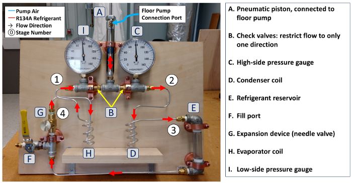
1. Fabrication of refrigeration system (see diagram and photograph, Fig. 3)

Figure 3: a. Diagram of components and connections in experimental vapor compression refrigeration system. Please click here to view a larger version of this figure.

Figure 4: T - s (a) and P - h (b) diagrams for experimental R-134a vapor compression refrigeration cycle.
2. Charging the refrigeration system
3. Operation
Refrigeration systems are ubiquitous, and they have an enormous impact on our day to day lives. Any time you store food in the refrigerator or freezer, or turn on the air conditioner, you are putting refrigeration systems to use. Fundamentally, the task of these systems is to remove heat from a cold reservoir and deposit it in a warm reservoir, against the natural direction of heat flow. The dominant technology employed to achieve this is the vapor compression cycle. This video will illustrate how the vapor compression cycle works, and then demonstrate how it is used in a simple hand pumped refrigeration system. At the end, it will discuss a few additional applications.
The vapor compression cycle is a thermodynamic cycle performed on a working fluid, or refrigerant, such that heat will flow into the refrigerant from the cold reservoir and out of the refrigerant to the hot reservoir. This requires mechanical circulation of the refrigerant as well as coordinated transitions of its thermodynamic state. The cycle takes advantage of the vapor dome, a region of the refrigerant phase space that can be seen in the temperature entropy and pressure enthalpy diagrams. In these diagrams, the left region indicates liquid phase, which is partially bounded by the saturated liquid line, and the right region indicates vapor phase, which is similarly bounded by the saturated vapor line. The saturation lines meet at the critical point, above which the fluid is super critical. Between the saturation lines, the fluid is two phase and temperature is a function of pressure as indicated by the isotherms on the pressure enthalpy diagram. In this region, temperature and pressure cannot be varied independent of each other, so each value of pressure specifies a temperature. Therefore, the temperature of a two phase mixture can be adjusted by changing the pressure. With this in mind, let's examine the vapor compression cycle. For illustration purposes, assume R-134a is the refrigerant and a mass flow rate of 0.01 kilograms per second. There are four stages in the cycle: compression, condensation, expansion, and evaporation. Each describes a transition between key stay points of the refrigerant. During compression, low pressure vapor enters the compressor and work input to the compressor is used to pressurize the refrigerant. After leaving the compressor, the high pressure vapor passes to the condenser, here, heat is rejected to the surrounding hot reservoir as the refrigerant condenses isobarically. The high pressure refrigerant now in liquid phase, then flows through a throttling expansion device. The liquid expands isentropically when passing through, and as it's pressure drops, flashes to a two phase state, and drops to a lower temperature. In the last stage, the low temperature refrigerant enters the evaporator and absorbs heat from the cold reservoir. This drives isobaric evaporation as the refrigerant flows through. The cycle is completed when the low pressure refrigerant vapor returns to the compressor. In this example, the cooling capacity of the evaporator is 1.67 kilowatts, and the compressor work input is 0.31 kilowatts, thus the coefficient of performance, or system efficiency, is 5.4. Now that you understand how the cycle works, let's build and analyze a simple refrigerator to show these principals in action.
Caution, this experiment involves systems at elevated pressures and the use of refrigerants, which can be hazardous at high concentrations. Always follow reasonable safety precautions and wear appropriate personal protective equipment. Ensure adequate ventilation when working with refrigerants. Begin construction of the refrigerator system with the vapor compressor. Install a Schrader valve on one port of a double action pneumatic cylinder, and then connect a pipe fitting tee to the other port. Attach check valves on the two remaining ports of the tee, so that one points inward and the other points outward. This configuration will allow refrigerant to be drawn in from the evaporator and expelled to the condenser at high pressure. The compressor will be actuated by a modified high pressure bicycle floor pump. Remove the rubber bead check valve component from the bicycle pump plumbing. This will allow the compressor to expand and draw in refrigerant in between pumping strokes. Install pipe fitting tees with pressure gauges on both sides of the compressor, so that the upstream and downstream pressure can be monitored. The tee fittings are connected through check valves, which only allow flow in one direction. When the piston is extended, the left check valve allows inflow from the low pressure evaporator to the compressor volume. When the piston is depressed, the vapor is pressurized and forced through the right check valve to the high pressure condenser. By cycling the piston, a continuous stream of low pressure vapor can be drawn from the evaporator and delivered to the condenser at high pressure. The next stage of system is the condenser, which we will construct from a length of aluminum tubing. Form the tubing into a coil, by wrapping it around a 2.5 centimeter diameter rigid rubber core for four turns, and then, use a compression fitting to attach one end to the open port of the tee, downstream of the compressor. Make sure to install and tighten the fittings to manufacturer guidelines. Next install a short length of clear PVC pipe between two reducing pipe elbows. This will act as the reservoir for the high pressure refrigerant, connected to the outlet of the condenser tubing with another compression fitting. The next stage is the expander, but this is also a convenient place to add a charging port for filling and draining refrigerant. Construct the charging port by combining an A.N.S.A.E. flare fitting connector with a ball valve and another pipe tee. Connect a needle valve to one side of the pipe tee for the expansion device. Finally, use another section of aluminum tubing to connect the third port of the pipe tee to the low point of the reservoir. The only remaining section is the evaporator. Form a second coil of aluminum tubing using the same technique as before, and connect it between the needle valve outlet and compressor inlet, to complete the refrigeration loop. Now that the system is assembled, fill it with compressed air through the charging port to test for any leaks. Use a soapy water spray to identify any leaky connections and make repairs as necessary. Finally, connect thermocouples to the condenser and evaporator coils for temperature measurement. You are now ready to charge and operate the refrigerator.
Charging is a two step process. Air is first evacuated from the system and then refrigerant is added. Connect the middle port of a refrigerant charging manifold, to the charging port on the refrigerator. Then connect a vacuum pump to the low pressure port of the manifold, and a can of refrigerant to the high pressure port. Close all of the valves and then turn on the vacuum pump. Gradually open all of the system valves to evacuate air from the system. After the air has been evacuated from the system, briefly open the refrigerant canister valve to clear any air from the refrigerant line, and then close it again. Now that all of the air has been evacuated, isolate the vacuum pump by closing the low pressure port on the refrigerant charging manifold. Invert the refrigerant canister and inject liquid refrigerant into the system until the level in the high pressure reservoir is slightly above the needle valve level. The last step is to adjust the needle valve until it is just barely open, and then connect the bicycle pump hose to the Schrader valve on the compressor. Operate the refrigerator by pumping the bicycle pump, as you do, track the high and low side pressures as well as the evaporator and condenser temperatures. When steady state conditions are reached, record these pressures and temperature values. If the gauges report gauge pressure, that is pressure relative to atmosphere, then convert the readings to absolute pressure by adding one atmosphere to the reading.
Take a look at the performance results for your refrigerator. First, compare the measured temperatures to the corresponding saturation temperatures of the refrigerant at the measured low and high pressures. In this case, the measurements closely match. The discrepancy of the evaporator temperature may be due to heat transfer from the ambient air to the exterior of the thermocouple. The condenser temperature matches to within experimental tolerance, but this could also appear warmer than expected if the thermocouple is placed too close to the super heated portion of the condenser. Finish the analysis by indicating the state points and approximate connecting curves on temperature entropy and pressure enthalpy diagrams. You can see that the simple system yields limited performance with low cooling capacity and low lift, compared to commercial systems. Since much of the input work is expended compressing air in the bicycle pump, performance could be improved with a lower pressure refrigerant. Additionally, using an expansion valve that can maintain a larger pressure difference would be beneficial. Most commercial systems employ a temperature controlled expansion valve, which dynamically adjusts its opening to maintain a desired evaporator temperature. Now that we've analyzed the basic process, lets look at some other typical applications.
The vapor compression cycle is the dominant refrigeration technology used in many common place devices. Thermomanagement for electronics has become increasingly important as the size of components has steadily decreased, while demands for power and speed have grown. Cooling super computers and other high powered electronics using the vapor compression cycle, has many advantages over other technologies. The vapor compression cycle can also be used as a heat pump. In this mode, heat is acquired in the evaporator from low temperature surroundings and then delivered to a warmer conditioned space. This can be an efficient mode of heating compared to direct resistance heating, because most of the delivered heat is drawn from the surroundings, and only a small portion is supplied to the compressor as mechanical work.
You've just watched Jove's introduction to refrigeration and the vapor dome. You should now understand how the vapor compression cycle is implemented in refrigeration systems, and how to analyze performance using temperature entropy and pressure enthalpy diagrams. Thanks for watching.
View the full transcript and gain access to JoVE Science Education videos
Q1: What is the vapor compression cycle and how does it work?
The vapor compression cycle is a thermodynamic process that removes heat from a cold reservoir and deposits it in a warm reservoir, against natural heat flow. It consists of four stages: compression, where work pressurizes low-pressure vapor; condensation, where high-pressure vapor releases heat; expansion, where pressure drops and the refrigerant cools; and evaporation, where low-temperature refrigerant absorbs heat from the cold space.
Q2: How does the vapor dome relate to refrigerant phase transitions?
The vapor dome is a region in temperature-entropy and pressure-enthalpy diagrams bounded by saturated liquid and vapor lines. Within this two-phase region, temperature and pressure are dependent—changing pressure automatically adjusts temperature. This property allows refrigeration systems to control the refrigerant's temperature by manipulating pressure, enabling efficient heat transfer during evaporation and condensation stages.
Q3: What role does the compressor play in a refrigeration system?
The compressor draws low-pressure vapor from the evaporator and uses mechanical work input to pressurize the refrigerant, raising it to high pressure. This pressurization is essential for the cycle because it enables the refrigerant to condense at higher temperatures in the condenser, allowing heat rejection to the surrounding environment. The compressor essentially drives the entire refrigeration cycle.
Q4: How is coefficient of performance calculated for a refrigeration system?
Coefficient of performance (COP) measures system efficiency by dividing cooling capacity by compressor work input. For example, if an evaporator provides 1.67 kilowatts of cooling and the compressor requires 0.31 kilowatts of work, the COP is 5.4. A higher COP indicates greater efficiency, meaning more cooling is achieved per unit of mechanical work supplied to the system.
Q5: What happens during the throttling expansion stage in refrigeration?
During throttling expansion, high-pressure liquid refrigerant passes through a restriction device and undergoes isentropic expansion. As pressure drops, the refrigerant flashes into a two-phase mixture and its temperature decreases significantly. This cold, low-pressure mixture then enters the evaporator where it absorbs heat from the cold reservoir, completing the cycle's heat acquisition phase.
Q6: Why is refrigerant charging a two-step process in refrigeration systems?
Refrigerant charging requires two steps: evacuation and charging. First, air is removed from the system using a vacuum pump to prevent contamination and ensure proper operation. Then, liquid refrigerant is injected into the system. This two-step approach prevents air pockets and moisture from interfering with heat transfer and thermodynamic performance, ensuring the system operates at design specifications.
Q7: How can the vapor compression cycle be used as a heat pump?
In heat pump mode, the vapor compression cycle reverses its function: the evaporator acquires heat from low-temperature surroundings, and the condenser delivers this heat to a warmer space. This mode is efficient for heating because most delivered heat comes from the environment, with only a small portion supplied as mechanical work to the compressor, making it superior to direct resistance heating.