

Summary
Here, we present a protocol describing a mold-free fabrication process of the polymeric microneedles by photolithography.
Abstract
This manuscript describes the fabrication of polymeric microneedle (MN) arrays by photolithography. It involves a simple mold-free process by using a photomask consisting of embedded micro-lenses. Embedded micro-lenses were found to influence MN geometry (sharpness). Robust MN arrays with tip diameters ranging between 41.5 µm ± 8.4 µm and 71.6 µm ± 13.7 µm, with two different lengths (1,336 µm ± 193 µm and 957 µm ± 171 µm) were fabricated. These MN arrays may provide potential applications in delivery of low molecular and macromolecular therapeutic agents through skin.
Introduction
Transdermal drug delivery offers an attractive alternative approach for drug administration, especially for biomolecules, which are almost exclusively administered by hypodermic injections. However, skin, especially the top layer (the stratum corneum), is a formidable barrier preventing exogenous molecules from entering the human body. Recently, MN devices have emerged as enabling tools to deliver drugs through skin. The MN devices create temporary pores inside the stratum corneum to allow the passage of drug molecules to achieve the desired physiological activity with improved patient compliance and convenience1-3.
Various fabrication methods have been adopted to fabricate polymeric MNs4. However, they usually involve complicated and multiple step processes requiring long times and/or high temperatures to fabricate MNs arrays.4 To simplify the fabrication process, a single step mold-free process using a photomask was developed recently5,6. However, with this method, fabricated MNs had blunt needle tips, as no mechanism was in place to modify the ultraviolet (UV) light path involved in photolithography.
In this study, embedded microlenses in the photomask have been proposed to define the geometry of the MNs. The protocol to fabricate photomasks consisting of embedded microlenses and subsequently MN fabrication with sharp tips using the photomask are reported.
Subscription Required. Please recommend JoVE to your librarian.
Protocol
1. Photomask Fabrication
- Clean a 4” glass wafer with piranha solution (H2SO4/H2O2 in 2:1 ratio) for 20 min at 120 °C by immersion in a quartz tank.
- Deposit a layer of Chromium/Gold (30 nm of Cr/1 µm of Au) layer on the glass wafer using an e-beam evaporator7 (Figure 1A).
- Place the wafers in an e-beam evaporator. Once the vacuum reaches 5 x 10⁻⁶ Torr, turn on the high voltage source (10 kV). Control the thickness by the monitor control panel.
- Pre-clean each material for 30 sec using the e-beam gun, keeping the shutter “OFF” (in order to avoid the deposition on the wafers).
- Generate a Cr/Au photoresist masking layer for deep wet etching of the glass.
- Apply a 2 µm thick photoresist by spinning 5 ml of the solution for 30 sec at 3,000 rpm using a spin-spray coater system. Prebake the photoresist on a hotplate at 100 °C for 1.5 min.
- Expose and hard bake the photoresist at 120 °C for 30 min on a hot plate. It is critical to generate a hydrophobic surface and a strong adhesion of the photoresist to the metal layer. Pattern the Cr/Au layer using Cr and Au etchants through the photoresist mask8,9.
- For protection of the un-patterned glass surface, temporarily bond the glass wafer to a dummy silicon wafer.9
- Place the glass wafer on a hot plate at 110 °C and melt the wax on the opposite side of the glass wafer (in such a way that the entire surface of the wafer is covered with wax).
- Place a dummy silicon wafer in contact with the glass wafer and press to remove the excess wax. In order to avoid spilling of the wax, place a clean room tissue paper on the hotplate.
- Perform isotropic etching of the lens using optimized hydrofluoric acid (49% v/v) and hydrochloric acid (37% v/v) solution ( in a volumetric ratio of 10:1) with a magnetic stirrer for 8.5 min.10 Presence of the HCl is critical in achieving a good surface quality of generated lenses.
- Ensure that the etching rate is 7 µm/min; using a total volume of 200 ml of etching solution. Perform etching in a plastic container and take safety precaution for this processing step.
- Clean the wafer in the deionized (DI) water by rinsing and further drying at RT.
- After the process completion, separate the glass wafer from the dummy silicon wafer and warm up the wax using a hot plate at 100 °C for 15 sec. As the wax melts at this temperature, detach the glass wafer from the dummy silicon wafer.
- Remove remaining wax, the photoresist and the overhanging Cr/Au layers at the edges of the lenses using ultrasonication for 1 hr using N-methyl-2-pyrrolidone as the solvent at 80 °C in an ultrasonic tank.
- Create a PDMS mold replica of the microlenses fabricated on the photomasks11.
- Characterize the photomask dimensions (length and width) and the microlenses PDMS mold (depth and diameter) replicas using a scanning electron microscope and stereomicroscope respectively.12-14
2. MN Shafts Fabrication
- Create a cavity of 2.5 cm × 0.9 cm using the glass slides mounted on either sides of a glass. The number of the glass slides stacked on either side will determine the height of the cavity known as spacer thickness (Figure 1B).
- Secure each layer of the glass slide by applying a thin layer of the prepolymer solution containing Poly(ethylene glycol) diacrylate (PEGDA, MW = 258 Da) with 0.5% w/w 2-hydroxy-2-methyl-propiophenone (HMP) onto the glass slide followed by irradiation of the set up with the high intensity ultraviolet (UV) light for 2 sec.
- Position the photomask (previously fabricated) with the Cr/Au coated surfaces facing the interior of the cavity. Ensure that the sides of the cavity walls are not obscuring the lenses embedded in the photomask.
- Fill the cavity with the prepolymer solution until the Cr/Au coated surface is in contact with the solution without any visible bubbles.
- Irradiate the setup with high intensity UV light of a desired intensity for 1 sec at a distance of 3.5 cm from the UV source using the UV curing station with a UV filter range of 320-500 nm. Use a collimating adaptor with the UV light probe.
- Measure the intensity of UV light used using a radiometer.
- Following UV exposure, remove the photomask with the array of MNs. Pour the excess prepolymer solution that is not polymerized in the process back into its original container for reuse.
- Quantify the length and tip diameter of the MNs using a stereomicroscope according to manufacturer’s instructions.
3. MN Backing Layer Fabrication
- With forceps, place the MNs (previously fabricated) attached onto the photomask in a well of a 24-well plate as shown in the Figure 1C.
- Add a specified volume (300 - 400 µl) of the prepolymer solution into the well until the needles are submerged to a desired height. This volume determines the thickness of the resultant backing layer.
- Irradiate the setup with high intensity UV light (15.1 W/cm2), 10.5 cm away from the UV source for a duration of 1 sec.
- Separate the backing layer on the MN array from the photomask using a sharp blade.
- Quantify the length, tip diameter and base diameter of the MNs with the backing layer using a stereomicroscope according to manufacturer’s instructions.
Subscription Required. Please recommend JoVE to your librarian.
Representative Results
The geometry of the MNs can be significantly affected by the photomask characteristics and embedded microlens. The degree of refraction affects the transmission path of the UV rays, which influenced the MN geometry (Figure 2A). Each microlens was found to have a 350 µm diameter, a 130 µm flattened convex surface, and a 62.3 µm depth (Figure 2B-D). Using the Pythagoras theorem, the radius of curvature of the first surface was found to be 272.89 µm. The focal length was calculated to be 509.28 µm (considering nglass=1.53627; nair = 1.000; λ=365 nm) via the lens maker equation12 as stated below:
1/f = (n1/nm-1) * (1/r1-1/r2)
Where n1 is the refractive index of lens material, nm is the refractive index of ambient medium, r1 is the radius of curvature of the first surface, and r2 is the radius of curvature of the second surface.
The effect of UV intensity on the MN length, sharpness and structural deformation was studied by varying intensity of the UV light from 3.14 to 15.1 W/cm2 at a constant focal length and light source distance. It was found that the average MN length significantly increased (p < 0.05) with increasing intensity from 3.14 to 9.58 W/cm2 (Figure 3A). Further increases in intensity up to 15.1 W/cm2 did not produce significant changes in the length. The tip diameter (measure of sharpness) and the MN tip structure were found to vary with increases in intensity (Figure 3B). The MNs with a regular shape and without any structural deformation were observed at 6.4 W/cm2.
The backing layer was fabricated to enable the removal of MN in form of a patch and to make the photomask reusable. It also provided strength to the MN shafts. Therefore, the effect of the backing layer volume (the volume of the prepolymer solutions to form the back layer) was also studied. With unaffected tip diameters, the MNs with a range of the length (1,336 ± 193 µm for 300 µl and 957 ± 171 µm for 400 µl) were observed after the UV exposure (Figure 4).

Figure 1. (A) Schematic representation of the fabrication process of lenses embedded photomask. (1) 4” glass wafer. (2) Cr/Au layer deposited using an e-beam evaporator. (3) Exposure of Cr/Au/photoresist masking layer to UV light with photomask. (4) Formation of pattern on layer using Cr/Au etchant. (5) Temporary bonding of glass on a dummy silicon wafer. (6) – (7) Wet etching (isotropic) process using HF/HCl etchants followed by ultrasonication. (8) Debonding of dummy silicon wafer and removal of photoresist layer. (B) Schematic representation of the fabrication process of needles. Chromium coated photomask (9 x 9 arrays), is placed over a cavity containing pre-polymer solution and exposed to UV. (C) Schematic representation of the fabrication process of the backing layer. Photomask, with microneedles attached, is placed in a well filled with pre-polymer and exposed to UV. Please click here to view a larger version of this figure.

Figure 2. Characterization of photomask. (A) UV exposure focuses light into a conical path, producing tapered MNs. (B) and (C) A SEM image of a microlens. (D) A portion of an array of PDMS mold replicas copied from the microlenses, showing the flattened convex surface, under a stereomicroscope. (E) A photomask showing the pattern. Please click here to view a larger version of this figure.

Figure 3. Effect of UV parameters on microneedle geometry. Effect of (A) intensity and (B) spacer thickness on microneedle length. Please click here to view a larger version of this figure.
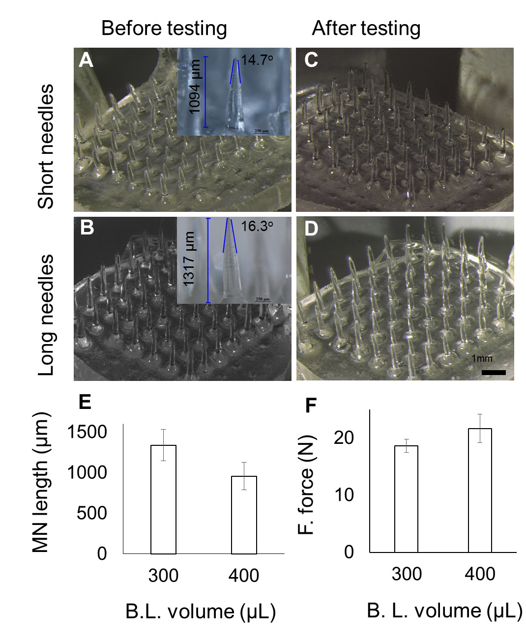
Figure 4. Effect of varying pre-polymer volume used for backing layer fabrication. (A-B) images at various volume, with average MN length for short (957 µm) and long (1,336 µm) MNs. (C-D) Images corresponding to (A-B) after fracture force testing. (E) Decrease in MN length with increase in volume used for backing layer fabrication. (F) MN fracture force across the two pre-polymer volumes used to fabricate backing layer (B.L.). Please click here to view a larger version of this figure.
Subscription Required. Please recommend JoVE to your librarian.
Discussion
The protocol described above for fabrication of the MNs array has been presented to fabricate the MNs array of ~1 cm2. The arrays can be scaled up by creating a large size cavity and by using a larger photomask. The increased cavity size can be created by increasing the width between the spacers on either side. Though each step to fabricate the MN arrays in the protocol was important, the most crucial steps were: the photomask positioning, the filling of prepolymer solution, and irradiation of the setup. Positioning of the photomask should be in such a way that the Cr/Au coated surfaces face the interior of the cavity and the sides of the cavity walls obscure the lenses embedded in the photomask. When filling the mold with the prepolymer solution, ensure that air bubbles are not entrapped which can otherwise lead to a deformed and low strength MN array. The air bubbles can be prevented through a controlled wicking action by slowly adding the prepolymer solution and ensuring that there are no air bubbles present in the prepolymer solution. Positioning of the setup for irradiation should be done in a guided manner to ensure uniform UV exposure. Before the exposure to UV light, the setup was aligned and placed within the demarcation on the base stand.
The MNs formed using photolithography were greatly influenced by the presence of the micro-lenses as the lens resulted in polymerization in a converged path, which led to the formation of the sharper MNs as compared to the cylindrical MNs formed using the planar photomask. In the planar photomask, the UV light passes through it with little deviation (almost straight) resulting in formation of the cylindrical MNs with less sharp tips. While in the microlens-embedded photomask, the UV light passing through the lenses underwent refraction and converged, resulting in the formation of sharp tipped MNs. The lens maker's equation which has been used as a predictive model to approximate the length of the MN by correlating with the focal length of the microlens gave a prediction of the length three times less than the real. The discrepancy may be due to the flattened convex surface of the microlens, which did not allow light refraction like the conventional convex lens.13
Another factor for the MN geometry was the UV light intensity. The intensity of 6.44 W/cm2 was chosen because the needles produced at this intensity possessed enough mechanical strength for skin applications. Another finding related to intensity was that with each increment in the UV intensity, the length of MN increases. This could be attributed to the flat top of the microlens, which allowed some of the light rays to travel beyond the focal point.14,15 Furthermore, the extent of polymerization has its limit, depending on the inverse-square law of the light, i.e., the light loses energy as the distance away from the source increases.16
The protocols described here have the advantage of mold-free fabrication within a short period of time. But we cannot predict how far it can be taken further for bulk manufacturing. The MNs arrays were made from a low cost biocompatible polymer. It can potentially be used as transdermal drug delivery device for pharmaceutical and cosmetic applications. More interestingly, it can be used as a combination of the delivery system and device, as the therapeutic compounds may be encapsulated (by mixing or solubilizing in prepolymer solution) during the fabrication of MNs.5,6,17 The solubility of the added compound inside the prepolymer solution should be taken into consideration as the MN characteristics, e.g., MN strength, may change.17
Subscription Required. Please recommend JoVE to your librarian.
Disclosures
The authors declare no conflict of Interest.
Acknowledgments
This study was supported by a Singapore National Research Foundation (NRF) Grant NRF2012NRF-POC001-043.
Materials
| Name | Company | Catalog Number | Comments |
| Poly(ethylene glycol) diacrylate (PEGDA Mn=258) | SIGMA | 475629-500ML | |
| 2-hydroxy-2-methyl-propiophenone (HMP) | SIGMA | 405655-50ML | |
| Bovine collagen type 1, FITC conjugate | SIGMA | C4361 | |
| UV curing station | EXFO Photonic Solutions Inc., Canada | OmniCure S2000-XL | |
| Collimating Adaptor | EXFO Photonic Solutions Inc., Canada | EXFO 810-00042 | |
| 24-well plate | Thermo Fisher Scientific, USA | ||
| Nikon SMZ 1500 stereomicroscope | Nikon, Japan | ||
| Dillon GL-500 digital force gauge | Dillon, USA | ||
| A-1R confocal microscope | Nikon, Japan |
References
- Zhou, C. P., Liu, Y. L., Wang, H. L., Zhang, P. X., Zhang, J. L. Transdermal delivery of insulin using microneedle rollers in vivo. International journal of pharmaceutics. 392, 127-133 (2010).
- Lee, J. W., Choi, S. O., Felner, E. I., Prausnitz, M. R. Dissolving microneedle patch for transdermal delivery of human growth hormone. Small. 7, 531-539 (2011).
- Raphael, A. P., et al. needle-free vaccinations in skin using multi layered, densely-packed dissolving microprojection arrays. Small. 6, 1785-1793 (2010).
- Lee, J. W., Han, M. R., Park, J. H. Polymer microneedles for transdermal drug delivery. Journal of drug targeting. 21, 211-223 (2012).
- Kochhar, J. S., Goh, W. J., Chan, S. Y., Kang, L. A simple method of microneedle array fabrication for transdermal drug delivery. Drug development and industrial pharmacy. 39, 299-309 (2013).
- Kochhar, J. S., Zou, S., Chan, S. Y., Kang, L. Protein encapsulation in polymeric microneedles by photolithography. International journal of nanomedicine. 7, 3143-3154 (2012).
- Tay, F. E. H., Iliescu, C., Jing, J., Miao, J. Defect-free wet etching through pyrex glass using Cr/Au mask. Microsystem Technologies. 12, 935-939 (2006).
- Iliescu, C., Chen, B., Miao, J. On the wet etching of Pyrex glass. Sensors and Actuators, A: Physical. 143, 154-161 (2008).
- Iliescu, C., Taylor, H., Avram, M., Miao, J., Franssila, S. A practical guide for the fabrication of microfluidic devices using glass and silicon. Biomicrofluidics. 6, 16505-16516 (2012).
- Iliescu, C., Jing, J., Tay, F. E. H., Miao, J., Sun, T. Characterization of masking layers for deep wet etching of glass in an improved HF/HCl solution. Surface and Coatings Technology. 198, 314-318 (2005).
- Pan, J., et al. Fabrication of a 3D hair follicle-like hydrogel by soft lithography. Journal of biomedical materials research. Part A. 101, 3159-3169 (2013).
- Jay, T. R., Stern, M. B. Preshaping photoresist for refractive microlens fabrication. P Soc Photo-Opt Ins. 1992, 275-282 (1993).
- Friedman, G. B., Sandhu, H. S. Longitudinal Spherical Aberration of a Thin Lens. Am J Phys. 35, 628 (1967).
- Xu, Q. A., Li, J., Zhang, W. Collimated the laser diode beam by the focus lens. Semiconductor Lasers and Applications IV. 7844, (2010).
- Lin, T. W., Chen, C. F., Yang, J. J., Liao, Y. S. A dual-directional light-control film with a high-sag and high-asymmetrical-shape microlens array fabricated by a UV imprinting process. J Micromech Microeng. 18, (2008).
- Dunne, S. M., Millar, B. J. Effect of distance from curing light tip to restoration surface on depth of cure of composite resin. Prim Dent Care. 15, 147-152 (2008).
- Kochhar, J. S., et al. Microneedle integrated transdermal patch for fast onset and sustained delivery of lidocaine. Molecular pharmaceutics. 10, 4272-4280 (2013).
- Kochhar, J. S., et al. Direct microneedle array fabrication off a photomask to deliver collagen through skin. Pharmaceutical research. 31, 1724-1734 (2014).
