C-arm-free oblique lumbar interbody fusion at the L5-S1 level (OLIF51) and simultaneous pedicle screw fixation are performed in a lateral position under navigation guidance. This technique does not expose the surgeon or operating staff to radiation hazards.
A subscription to JoVE is required to view this content. Sign in or start your free trial.
Method Article
C-arm-Free Simultaneous OLIF51 and Percutaneous Pedicle Screw Fixation in a Single Lateral Position
In This Article
Summary
Abstract
Oblique lumbar interbody fusion (OLIF) is an established technique for the indirect decompression of lumbar canal stenosis. However, OLIF at the L5-S1 level (OLIF51) is technically difficult because of the anatomical structures. We present a novel simultaneous technique of OLIF51 with percutaneous pedicle screw fixation without fluoroscopy. The patient is placed in a right lateral decubitus position. A percutaneous reference pin is inserted into the right sacroiliac joint. An O-arm scan is performed, and 3D reconstructed images are transmitted to the spinal navigation system. A 4 cm oblique skin incision is made under navigation guidance along the pelvis. The internal/external and transverse abdominal muscles are divided along the muscle fibers, protecting the iliohypogastric and ilioinguinal nerves. Using a retroperitoneal approach, the left common iliac vessels are identified. Special muscle retractors with illumination are used to expose the L5-S1 intervertebral disc. After disc preparation with navigated instruments, the disc space is distracted with navigated trials. Autogenous bone and demineralized bone material are then inserted into the cage hole. The OLIF51 cage is inserted into the disc space with the help of a mallet. Simultaneously, percutaneous pedicle screws are inserted by another surgeon without changing the lateral decubitus position of the patient.
In conclusion, C-arm-free OLIF51 and simultaneous percutaneous pedicle screw fixation are performed in a lateral position under navigation guidance. This novel technique reduces surgical time and radiation hazards.
Introduction
Spondylosis is regarded as a stress fracture1 and occurs in about 5% of the young adult population2. The most common level of occurrence is at the L5 level due to the unique shearing force applied at the L5-S1 area. The main symptoms of spondylosis and spondylolisthesis are low back pain, leg pain, and numbness. If conservative treatment proves ineffective, surgical treatment is recommended3. Transforaminal lumbar interbody fusion (TLIF) is an effective and established technique4, but the nonunion rate of this procedure is relatively higher at the L5-S1 level5. Furthermore, with TLIF, it is difficult to create adequate lordosis compared to oblique lumbar interbody fusion (OLIF) or anterior lumbar interbody fusion (ALIF)6.
Indirect decompressions such as ALIF or OLIF are currently common methods for treating lumbar stenosis7. However, the conventional ALIF technique causes a large amount of muscle damage. Oblique lateral interbody fusion at the L5-S1 level (OLIF51) was first reported in 20178. Posterior instrument augmentation is usually necessary to ensure solid fusion, but the conventional OLIF technique uses a C-arm, and the patient position is changed from lateral to prone. To overcome these problems, we report herein a novel technique of C-arm-free simultaneous OLIF51 and percutaneous pedicle screws (PPSs) in a single lateral position.
We introduce the case of a 75-year-old woman with symptomatic L5 spondylolisthesis (grade 2).
Access restricted. Please log in or start a trial to view this content.
Protocol
This study was approved by the ethics committee at Okayama Rosai Hospital (No. 201-3).
1. Patient examination
- History taking
- Evaluate a patient with a suspected herniated disc or stenosis by taking their history. Usually, the patient presents with a history of prodromal low back pain. The patient may correlate their symptoms with an episode of trauma.
- Ask the patient to describe the radiating leg pain, its location, and aggravating and relieving activities.
- Physical examination
- To determine the level of the affected nerve, look for signs of motor weakness or loss of sensation in the leg. Check the lumbar range of motion, the straight leg raise (SLR) test, deep tendon reflexes, and muscle weakness.
- Perform the Kemp test to check the location of the herniated discs. If the Kemp test yields a positive result, local pain suggests a facet pathology, while radiating pain into the leg is more suggestive of nerve root irritation, which frequently accompanies foraminal disc herniation or stenosis.
NOTE: Usually, the SLR test is negative for patients with lumbar canal stenosis and positive for patients with lumbar disc herniation.
2. Evaluation of images
- Magnetic resonance imaging (MRI)
- Perform an MRI. This is the most accurate diagnostic modality for assessing lumbar disc herniation, showing the site of herniation and the nerve roots affected. The L5 nerve root can be compressed by fibrocartilage at the pars interarticularis of L5.
- Computed tomography (CT)
- Use CT to check whether the herniated disc is calcified and to rule out nerve compression by any osteophyte.
- CT-MRI fusion imaging
- Use the fusion image to evaluate the feasibility of performing OLIF51. The vascular window, made by the common iliac vessels at the L5-S1 disc level, is clearly visualized. A vascular window of less than 20 mm makes OLIF technically difficult (Figure 1).
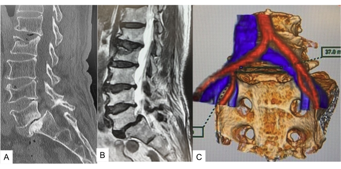
Figure 1: Preoperative image. (A) Midsagittal reconstruction CT, (B) T2 weighted midsagittal image, (C) CT MRI fusion image. CT and MRI show grade 2 isthmic spondylolisthesis. The vascular window is 37 mm. Please click here to view a larger version of this figure.
3. Patient positioning and neuromonitoring
- Patient positioning
- Place the patient in a right lateral decubitus position on a carbon table. Use an O-arm to obtain 3D images of the lumbar spine of the patient (Figure 2).
- To protect the neurovascular structures, place an axillary roll underneath the patient's right axilla.
- Flex the hip and knee to 20° to relax the psoas muscle and the lumbar nerve. Secure the patient to the table with tape.
- Insert a percutaneous reference pin into the left sacroiliac joint.
- Obtain 3D images of the O-arm and transmit them to the navigation system.
- Neuromonitoring
- Whenever possible, neuromonitor the patient to prevent neurological complications (Figure 3).
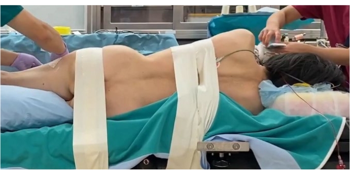
Figure 2: Patient positioning. Right lateral decubitus position secured with tape. Please click here to view a larger version of this figure.
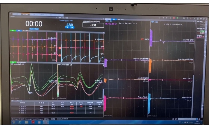
Figure 3: Neuromonitoring. Neuromonitoring is preferable for this technique. Please click here to view a larger version of this figure.
4. Intraoperative CT and spinal navigation
- Intraoperative CT
- Place a navigation reference frame (RF) percutaneously into the contralateral sacroiliac joint or L5 spinous process, and obtain intraoperative CT images (Figure 4).
- Navigation
- The navigation system is necessary for this technique. Transmit the CT 3D reconstructed images to the navigation system (Figure 5).

Figure 4: O-arm. One O-arm scan is just 23 s. Please click here to view a larger version of this figure.

Figure 5: Navigation system. Every instrument is navigated with this system. Please click here to view a larger version of this figure.
5. Navigated instrument registration
- Register every navigated instrument and perform an accuracy check.
6. Incision and muscle dissection
- Skin incision
- Mark the skin incision using a navigated pointer. Direct the entry point to the center and parallel to the L5-S1 disc space.
- Make a 4 cm long oblique incision on the skin, 4 cm medial to the anterior superior iliac spine and parallel to the pelvis (Figure 6).
- Muscle dissection
- Divide the abdominal muscles and dissect along the line of the skin incision. A monopolar cautery is contraindicated due to the risk of injury to the iliohypogastric and ilioinguinal nerves.
- With a retroperitoneal approach, use both index fingers to dissect the retroperitoneal space, following the internal abdominal wall posteriorly down to the psoas muscle, which can then be visualized (Figure 7).
CAUTION: If the iliohypogastric nerve is injured, abdominal herniation may occur.
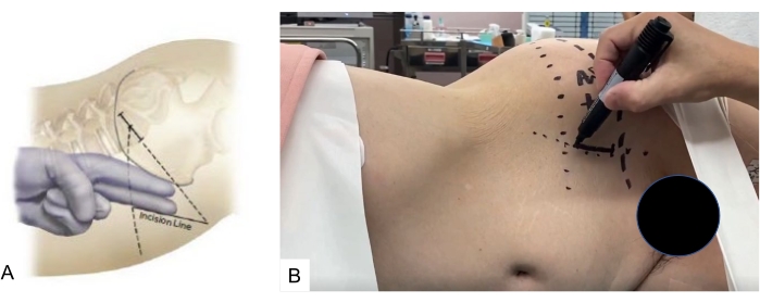
Figure 6: Skin incision. The skin is marked using a navigated pointer, which is directed to the center and parallel to the L5-S1 Please click here to view a larger version of this figure.
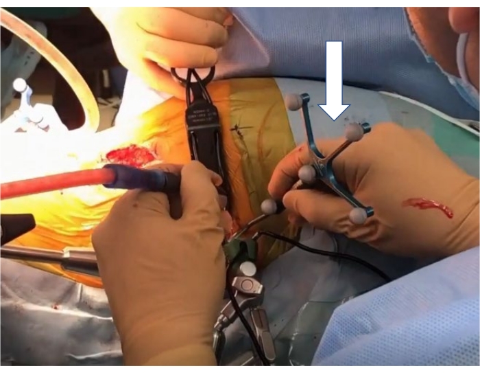
Figure 7: Navigated pointer. The white arrow indicates a navigated pointer. Please click here to view a larger version of this figure.
7. Disc preparation and trialing
- Disc preparation
- After exposing the promontorium, identify the left common iliac vessels and retract laterally (upward) using a special self-retaining retractor under illumination. Take great care to preserve the left ureter. The L5/S1 intervertebral disc is exposed (Figure 8).
- Retract both common iliac vessels and the bifurcation with three self-retaining retractors. A blunt dissection of the adventitial layers on the L5/S1 disc is necessary to not injure the sympathetic chain. Retrograde ejaculation may occur in male patients if the sympathetic chain is injured.
- After the center of the disc is marked with a navigated pointer, incise the annulus with a knife, and perform a discectomy using Kerrison rongeurs, pituitary forceps, a navigated Cobb elevator, a navigated shaver (Figure 10), a navigated combo tool (periosteum elevator), and a navigated curved curette (Figure 11).
- Use the navigated curved curette to remove the posterior part of the disc.
NOTE: Since all the instruments are navigated, the use of an intraoperative C-arm is not required.
- Trialing
- After disc preparation, sequentially distract the disc space using navigated trials. Determine the size of the cage on a preoperative lateral radiogram. For Asian patients, a disc height of 10-14 mm and an angulation of 12°-18° is advisable.
- At this step, perform intraoperative radiography to check the implant position and the size of the cage. If the cage protrudes beyond the disc space, choose another adequately sized cage (Figure 12).
CAUTION: The surgeon should check the accuracy of the navigation system before using the navigation instruments, as the reference frame may sometimes be accidentally altered. Unlike the C-arm, the disc space in the navigation image does not open on insertion of a trial with an adequate height.
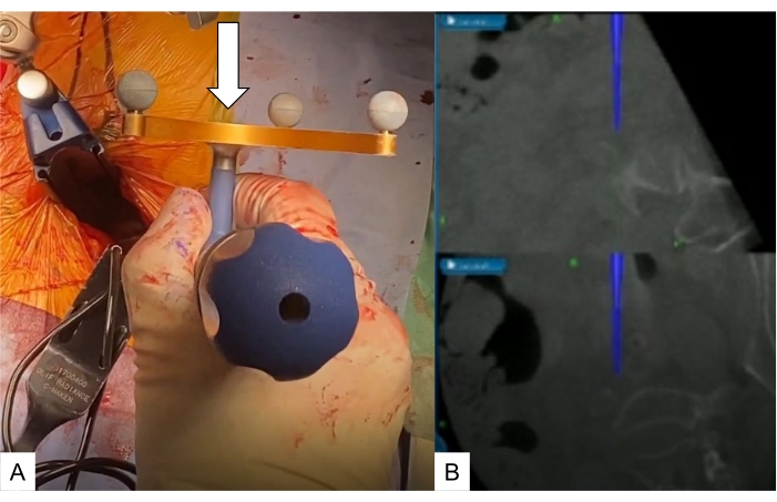
Figure 8: Approach to the promontorium. (A) Navigated pedicle probe, (B) navigation monitor. A navigated pedicle probe (white arrow) is used to check the L5-S1 disc level. Please click here to view a larger version of this figure.
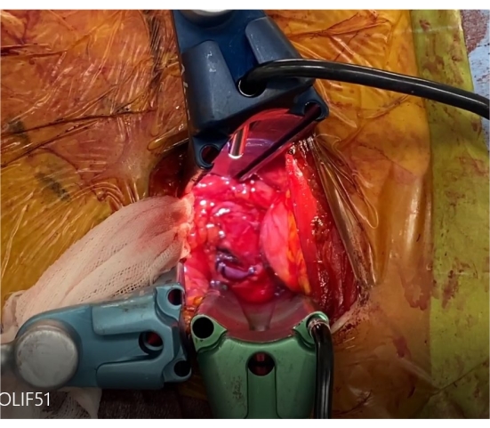
Figure 9: Self-retaining retractors. These three retractors retract both common iliac vessels and the bifurcation. Please click here to view a larger version of this figure.
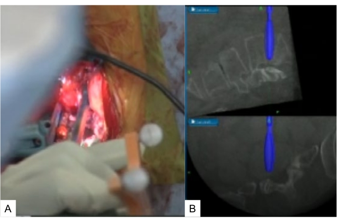
Figure 10: Navigated shaving. (A) Navigated shaver, (B) navigation monitor. Navigated shavers are from 6 mm to 12 mm. Please click here to view a larger version of this figure.
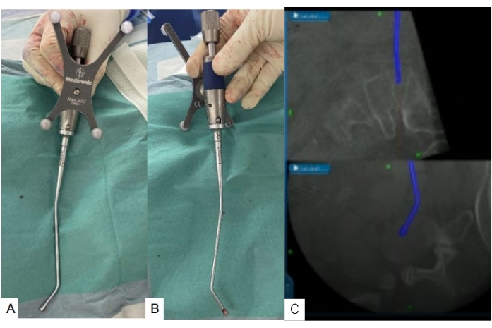
Figure 11: Navigated curved curette. (A) Navigated curved curette, (B) navigation monitor. A navigated curved curette is very useful to completely remove the posterior part of the disc. Please click here to view a larger version of this figure.
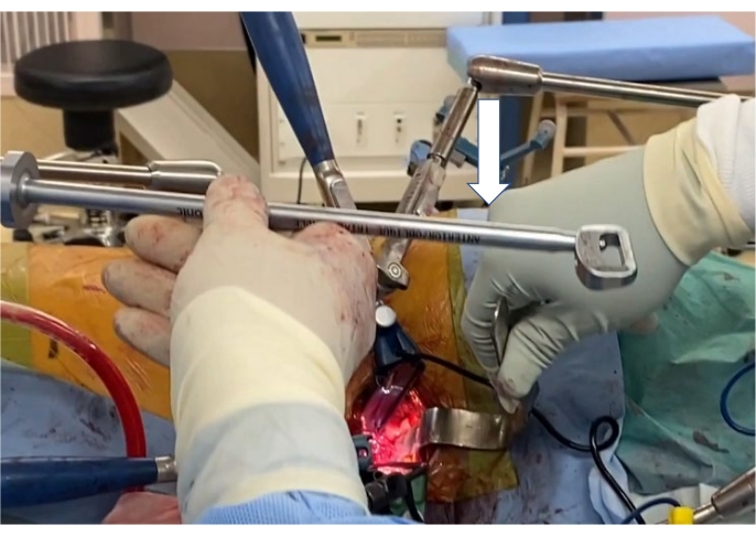
Figure 12: Trialing. After disc preparation, the disc space is sequentially distracted with navigated trials (white arrow). Please click here to view a larger version of this figure.
8. Cage placement and screwing
- Cage placement
- Insert a mixture of autogenous bone and demineralized bone material into the cage hole. Confirm the angle of insertion for the cage with a navigation pointer to insert the OLIF51 cage accurately.
- Use a mallet to gently insert the OLIF51 cage. After the implant is positioned, take anteroposterior and lateral radiographs to confirm the position of the cage (Figure 13A).
- Screwing
- After cage insertion, insert one or two supplemental screws to prevent cage back-out (Figure 13B).
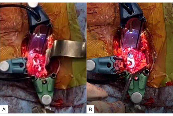
Figure 13: Cage placement and screwing. (A) OLIF51 cage at the L5-S1 disc, (B) cage with screw. A mixture of autogenous bone and demineralized bone material is inserted into the cage hole. Please click here to view a larger version of this figure.
9. Simultaneous percutaneous pedicle screw (PPS) fixation
- Have another surgeon insert the PPSs in the same lateral decubitus position of the patient under navigation guidance.
- Make the screw hole with a navigated high-speed burr, navigated pedicle probe, and navigated tap. Measure the length and diameter of the screws by navigation.
- Insert the S1 PPS in a transdiscal manner to enhance the screw pullout strength.
- Take radiograms after the insertion of the screws (Figure 14).
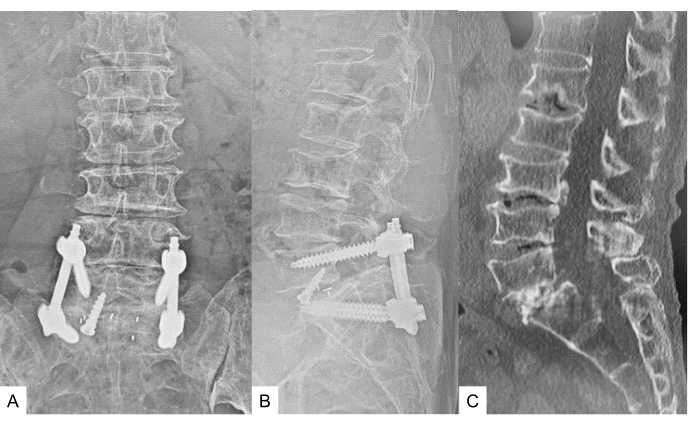
Figure 14: Simultaneous PPS fixation. PPSs are inserted in the same single lateral position by another surgeon under navigation guidance. Please click here to view a larger version of this figure.
10. Postoperative procedure
- Ambulate the patient 1 day after the surgery. The use of a soft brace is recommended for 3 months. Follow-up at 3 months, 6 months, and 12 months after the surgery to assess for solid bony fusion.
Access restricted. Please log in or start a trial to view this content.
Results
Fourteen cases (average age: 71.5 years) were treated using this new technique. They were compared to 40 cases (average age: 74.0 years) of L5-S1 TLIF. L5-S1 lordosis angle and disc height were measured in both groups. The OLIF51 group obtained a better L5-S1 lordosis than the TLIF 51 group (Figure 15).
Access restricted. Please log in or start a trial to view this content.
Discussion
Recently, the lateral lumbar approach for interbody fusion has been gaining popularity due to its minimal invasiveness9. Among these approaches, the direct lateral psoas splitting approach has several disadvantages, such as lumbar nerve plexus injury and psoas muscle weakness10. To reduce these complications, prepsoas or OLIF was introduced by Davis et al. in 201411. However, it is difficult to operate at the L5-S1 disc due to its anatomical features...
Access restricted. Please log in or start a trial to view this content.
Disclosures
The authors declare that there are no conflicts of interest.
Acknowledgements
This study was supported by the Okayama Spine Group.
Access restricted. Please log in or start a trial to view this content.
Materials
| Name | Company | Catalog Number | Comments |
|---|---|---|---|
| Adjustable hinged operating carbon table | Mizuho OSI | 6988A-PV-ACP | OSI Axis Jackson table |
| CD Horizon Solera Voyager | Medtronic | 6.4317E+11 | Percutaneous pedicle screw system |
| Navigated Cobb elevator | Medtronic | NAV2066 | |
| Navigated combo tool | Medtronic | NAV2068 | |
| Navigated curette | Medtronic | NAV2069 | |
| Navigated high speed bur | Medtronic | EM200N | Stelth |
| Navigated passive pointer | Medtronic | 960-559 | |
| Navigated pedicle probe | Medtronic | 9734680 | |
| Navigated shaver | Medtronic | NAV2071 | |
| NIM Eclipse system | Medtronic | ECLC | Neuromonitouring |
| O-arm | Medtronic | 224ABBZX00042000 | Intraoperative CT |
| Radiolucent open spine cramp | Medtronic | 9731780 | |
| Self-retaining retractor | Medtronic | 29B2X10008MDT151 | |
| Sovereign Spinal System | Medtronic | 6.4317E+11 | OLIF51 cage |
| Spine small passive frame | Medtronic | 9730605 | |
| Stealth station navigation system Spine 7R | Medtronic | 9733990 | Navigation |
| U-NavLock Gray | Medtronic | 9734590 | |
| U-NavLock Green | Medtronic | 9734734 | |
| U-NavLock Orange | Medtronic | 9734683 | |
| U-NavLock Violet | Medtronic | 9734682 |
References
- Tawfik, S., Phan, K., Mobbs, R. J., Rao, P. J. The incidence of pars interarticularis defects in athletes. Global Spine Journal. 10 (1), 89-101 (2020).
- Sonne-Holm, S., Jacobsen, S., Rovsing, H. C., Monrad, H., Gebuhr, P. Lumbar spondylolysis: A life long dynamic condition? A cross sectional survey of 4.151 adults. European Spine Journal. 16 (6), 821-828 (2007).
- McAfee, P. C., et al. The indications for interbody fusion cages in the treatment of spondylolisthesis: Analysis of 120 cases. Spine. 30 (6), 60-65 (2005).
- Parajon, A., et al. Minimally invasive transforaminal lumbar interbody fusion: Meta-analysis of the fusion rates. What is the optimal graft material. Neurosurgery. 81 (6), 958-971 (2017).
- Lowe, T. G., Tahernia, A. D., O'Brien, M. F., Smith, D. A. Unilateral transforaminal posterior lumbar interbody fusion (TLIF): Indications, technique, and 2-year results. Journal of Spinal Disorders and Techniques. 15 (1), 31-38 (2002).
- Mayer, H. M. A new microsurgical technique for minimally invasive anterior lumbar interbody fusion. Spine. 22 (6), 691-699 (1997).
- Hodgson, A. R., Stock, F. E., Fang, H. S. Y., Ong, G. B. Anterior spinal fusion the operative approach and pathological findings in 412 patients with Pott's disease of the spine. The British Journal of Surgery. 48, 172-178 (1960).
- Woods, K., Billy, J. B., Hynes, R. Technical description of oblique lateral interbody fusion at L1-L5 (OLIF25) and at L5-S1 (OLIF51) and evaluation of complication and fusion rates. The Spine Journal. 17 (4), 545-553 (2017).
- Tan, Y., et al. Comparison of simultaneous single-position oblique lumbar interbody fusion and percutaneous pedicle screw fixation with posterior lumbar interbody fusion using O-arm navigated technique for lumbar degenerative diseases. Journal of Clinical Medicine. 10 (21), 4938(2021).
- Phillips, F. M., et al. Adult degenerative scoliosis treated with XLIF: Clinical and radiographical results of a prospective multicenter study with 24-month follow-up. Spine. 38 (21), 1853-1861 (2013).
- Davis, T. T., et al. Retroperitoneal oblique corridor to the L2-S1 intervertebral discs in the lateral position: An anatomic study. Journal of Neurosurgery: Spine. 21 (5), 78(2014).
- Houten, J. K., Alexandre, L. C., Nasser, R., Wollowick, A. L. Nerve injury during the transpsoas approach for lumbar fusion. Journal of Neurosurgery: Spine. 15 (3), 280-284 (2011).
- Tanaka, M., et al. C-arm free simultaneous OLIF51 and percutaneous pedicle screw fixation in a single lateral position: A technical note. Interdisciplinary Neurosurgery. 27, 101428(2022).
- Hadelsberg, U. P., Harel, R. Hazards of ionizing radiation and its impact on spine surgery. World Neurosurgery. 92, 353-359 (2016).
- Kim, T. T., Drazin, D., Shweikeh, F., Pashman, R., Johnson, J. P. Clinical and radiographic outcomes of minimally invasive percutaneous pedicle screw placement with intraoperative CT (O-arm) image guidance navigation. Neurosurgical Focus. 36 (3), 1(2014).
- Kakarla, U. K., Little, A. S., Chang, S. W., Sonntag, V. K., Theodore, N. Placement of percutaneous thoracic pedicle screws using neuronavigation. World Neurosurgery. 74 (6), 606-610 (2010).
- Nagamatsu, M., et al. Assessment of 3D lumbosacral vascular anatomy for OLIF51 by non-enhanced MRI and CT medical image fusion technique. Diagnostics. 11 (10), 1744(2021).
- Tanaka, M., Fujiwara, Y., Uotani, K., Maste, P., Yamauchi, T. C-arm-free circumferential minimally invasive surgery for adult spinal deformity: Technical note. World Neurosurgery. 143, 235-246 (2020).
Access restricted. Please log in or start a trial to view this content.
Reprints and Permissions
