Kerry M. Dooley

Cain Department of Chemical Engineering

Louisiana State University

Kerry M. Dooley

Kerry M. Dooley is the BASF Professor in the Cain Department of Chemical Engineering and an Adjunct Professor of Chemistry at Louisiana State University. He was educated at Tulane University (B.S., ChE) and, after a short stint as a process engineer for DuPont, he received his Ph.D. in 1983 from the University of Delaware. His research is concentrated in heterogeneous catalysis (especially that by strong acids, zeolites and mixed metal oxides), processing of inorganic materials, and reactor design. He has published more than 125 combined articles, patents, and book chapters, edited 10 books, consulted for nine different companies, and performed contract research for 12 others. He was a Fulbright fellow at the University of Twente in the Netherlands in 1991.

Through the course of his career, he has taught 18 different classes at both the undergraduate and graduate level and developed 15 different instructional laboratory experiments at the undergraduate level.

Publications

Kinetics of Addition Polymerization to Polydimethylsiloxane

JoVE 10369

Source: Kerry M. Dooley and Michael G. Benton, Department of Chemical Engineering, Louisiana State University, Baton Rouge, LA

Polymers are molecules consisting of many repeating monomer units that are chemically bonded into long chains. They exhibit a broad range of physical properties, which are affected by their chemical structure, molecular weight and degree of polymerization. The polymer industry manufactures thousands of raw materials used in a broad variety of commercial products.1,2

The goal of this video is to perform an addition polymerization reaction and then evaluate the resulting product to understand how viscosity can be used to determine polymer molecular weight. Additionally, this experiment will investigate how molecular weight can be related to monomer conversion.

 Chemical Engineering

Demonstration of the Power Law Model Through Extrusion

JoVE 10382

Source: Kerry M. Dooley and Michael G. Benton, Department of Chemical Engineering, Louisiana State University, Baton Rouge, LA

Polymer melts are often formed into simple shapes or "extrudates", such as cylindrical pellets, flat sheets, or pipe, using an extruder.1 Polyolefins are among the most common extrudable polymers. Extrusion involves transporting and melting solid feed, which is sometimes mixed with non-polymeric materials, and the pressure build-up and transport of the melt or mixture. It is applied to thermoplastic polymers, which deform when heated and resume their earlier "no-flow" properties when cooled.

Using a simple lab extruder, the effect of operating conditions on polymer output and pressure drop can be examined and the resulting data can be correlated using the "Power Law" model for flow of polymer melts and solutions. This model is used to scale up the process to more complex extruders. The relationship between operating conditions and the deviations from theoretical displacement behavior ("slippage") and extrudate shape ("die swell") can be determined.

In this experiment, a typical thermoplastic polymer, such as a high-density polyethylene (HDPE) copolymer (of ethylene + a longer chain olefin) will be used. The operating temperature for the die and zones depend on the material. The flow rate can be determined by weighing the die output at timed intervals. All other necessary data (screw speed, zone temperatures, pressure entering the die) can be read from the instrument panel.

 Chemical Engineering

Crystallization of Salicylic Acid via Chemical Modification

JoVE 10407

Source: Kerry M. Dooley and Michael G. Benton, Department of Chemical Engineering, Louisiana State University, Baton Rouge, LA

Processing of biochemicals involves unit operations such as crystallization, ultracentrifugation, membrane filtration, and preparative chromatography, all of which have in common the need to separate large from small molecules, or solid from liquid. Of these, crystallization is the most important from a tonnage standpoint. For that reason, it is commonly employed in the pharmaceutical, chemical and food processing industries. Important biochemical examples include chiral separations,1 purification of antibiotics,2 separation of amino acids from precursors,3 and many other pharmaceutical,4-5 food additive,6-7 and agrochemical purifications.8 The control of crystal morphology and size distribution is critical to process economics, as these factors affect the costs of downstream processing operations such as drying, filtration, and solids conveying. For more information about crystallization, consult a specialized textbook or a Unit Operations textbook.9

The crystallizer unit (Figure 1) enables study of: (a) the effects of key parameters, such as supersaturation and cooling/heating rates, on solids content, morphology and crystal size distribution; (b) and the on-line control of crystallization processes. Supersaturation can be controlled by altering conditions such as agitation rate and temperature. The different classifications of crystallization include cooling, evaporative, pH swing and chemical modification. In this experiment,an offline microscope will measure from crystals ranging in size from 10-1000 μm, a typical size range for biologicals.
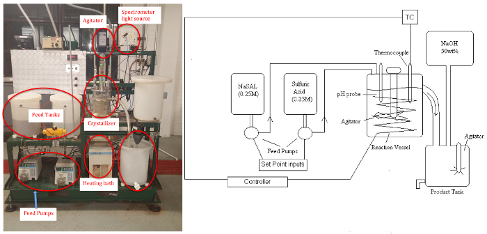
Figure 1
Figure 1: P&ID schematic (left)and picture (right)of Crystallizer. Please click here to view a larger version of this figure.

This experiment will demonstrate a "chemical modification",or "pH-swing" crystallization, to generate salicylic acid (SAL) (precursor of aspirin) crystals from the rapid reaction of aqueous solutions of basic sodium salicylate (NaSAL), which are basic, and sulfuric acid (H2SO4) at anywhere from 40 - 80°C.11

Na+SAL + 0.5 H2SO4 SAL (ppt) + Na+ + 0.5 SO42-

The byproduct sodium sulfate remains soluble. The apparatus consists of two feed tanks, three variable speed (peristaltic) pumps, the crystallizer (stirred tank to approximate uniform temperature and concentration, ~5 L), a circulating bath for temperature control, power controller, product tank, and a makeup tank for feed regeneration with NaOH solution (if desired). Samples will be analyzed by a UV-Vis spectrometer for the residual soluble salicylate ion, and the salicylic acid crystal product will be dried and weighed.A pH probe can be used to determine steady-state when reaction conditions are altered.

 Chemical Engineering

Liquid Phase Reactor: Sucrose Inversion

JoVE 10408

Source: Kerry M. Dooley and Michael G. Benton, Department of Chemical Engineering, Louisiana State University, Baton Rouge, LA

Both batch and continuous flow reactors are used in catalytic reactions. Packed beds, which use solid catalysts and a continuous flow, are the most common configuration. In the absence of an extensive recycle stream, such packed bed reactors are typically modeled as "plug flow". The other most common continuous reactor is a stirred tank, which is assumed to be perfectly mixed.1 One reason for the prevalence of packed bed reactors is that, unlike most stirred tank designs, a large wall area to reactor volume ratio promotes more rapid heat transfer. For almost all reactors, heat must either be added or withdrawn to control the temperature for the desired reaction to take place.

The kinetics of catalytic reactions are often more complex than the simple 1st order, 2nd order, etc. kinetics found in textbooks. The reaction rates can also be affected by rates of mass transfer - reaction cannot take place faster than the rate at which reactants are supplied to the surface or the rate at which products are removed - and heat transfer. For these reasons, experimentation is almost always necessary to determine the reaction kinetics prior to designing large-scale equipment. In this experiment, we explore how to conduct such experiments and how to interpret them by finding a reaction rate expression and an apparent rate constant.

This experiment explores the use of a packed bed reactor to determine the kinetics of sucrose inversion. This reaction is typical of those characterized by a solid catalyst with liquid phase reactants and products.

sucrose → glucose (dextrose) + fructose(1)

A packed bed reactor will be operated at different flow rates to control the space time, which is related to residence time and is analogous to elapsed time in a batch reactor. The catalyst, a solid acid, will first be prepped by exchanging protons for any other cations present. Then, the reactor will be heated to the desired temperature (isothermal operation) with the flow of reactants. When the temperature has equilibrated, product sampling will begin. The samples will be analyzed by a polarimeter, which measures optical rotation. The mixture's optical rotation can be related to the conversion of sucrose, which can then be used in standard kinetics analyses to determine the order of the reaction, with respect to the reactant sucrose, and the apparent rate constant. The effects of fluid mechanics - no axial mixing (plug flow) vs. some axial mixing (stirred tanks in series) - on the kinetics will be analyzed as well.

 Chemical Engineering

Vapor-liquid Equilibrium

JoVE 10425

Source: Michael G. Benton and Kerry M. Dooley, Department of Chemical Engineering, Louisiana State University, Baton Rouge, LA

Vapor-liquid equilibrium is paramount in engineering applications such as distillation, environmental modeling, and general process design. Understanding the interactions of components in a mixture is very important in designing, operating and analyzing such separators. The activity coefficient is an excellent tool for relating molecular interactions to mixture composition. Finding the molecular interaction parameters allows future prediction of the activity coefficients for a mixture using a model.

Vapor-liquid equilibrium is a critical factor in common processes in the chemical industry, such as distillation. Distillation is the process of separating liquids by their boiling point. A liquid mixture is fed into a distillation unit or column, then boiled. Vapor-liquid equilibrium data is useful for determining how liquid mixtures will separate. Because the liquids have different boiling points, one liquid will boil into a vapor and rise in the column, while the other will stay as a liquid and drain through the unit. The process is very important in a variety of industries.

In this experiment, the activity coefficients of mixtures of various compositions of methanol, isopropanol, and deionized water will be obtained using a vapor-liquid equilibrium apparatus and gas chromatograph. Additionally, the binary interaction parameters of the system will be determined using Wilson's equation and the activity coefficients.

 Chemical Engineering

Efficiency of Liquid-liquid Extraction

JoVE 10426

Source: Kerry M. Dooley and Michael G. Benton, Department of Chemical Engineering, Louisiana State University, Baton Rouge, LA

Liquid-liquid extraction (LLE) is a separation technique used instead of distillation when either: (a) the relative volatilities of the compounds to be separated are very similar; (b) one or more of the mixture components are temperature sensitive even near ambient conditions; (c) the distillation would require a very low pressure or a very high distillate/feed ratio.1The driving force for mass transfer is the difference in solubility of one material (the solute) in two other immiscible or partially miscible streams (the feed and the solvent). The feed and solvent streams are mixed and then separated, allowing the solute to transfer from the feed to the solvent. Normally, this process is repeated in successive stages using counter-current flow. The solute-rich solvent is called the extract as it leaves, and the solute-depleted feed is the raffinate. When there is a reasonable density difference between the feed and solvent streams, extraction can be accomplished using a vertical column, although in other cases a series of mixing and settling tanks may be used.

In this experiment, the operational goal is to extract isopropanol (IPA, ~10 - 15 wt. %, the solute) from a mixture of C8-to-C10 hydrocarbons using pure water as solvent. A York-Scheibel type (vertical mixers and coalescers, one each per physical stage) extraction column is available. Like most extractors, the overall efficiency (number theoretical stages/physical stages) of this column is quite low, especially in comparison to many distillation columns. The low efficiencies arise from both slow mass transfer (two liquid resistances instead of one as in distillation) and often also from maldistribution of the phases. The effect of agitator speed on both the solute recovery in the extract and the overall column efficiency will be evaluated.

 Chemical Engineering

Catalytic Reactor: Hydrogenation of Ethylene

JoVE 10427

Source: Kerry M. Dooley and Michael G. Benton, Department of Chemical Engineering, Louisiana State University, Baton Rouge, LA

The hydrogenation of ethylene (C2H4) to ethane (C2H6) has often been studied as a model reduction reaction in characterizing new metal catalysts.1-2 While supported nickel is not the most active metal catalyst for this reaction, it is active enough that reaction can take place at < 200°C.

The reaction typically involves adsorbed, dissociated hydrogen (H2) reacting with adsorbed ethylene. In other words, both hydrogen-atoms and ethylene molecules form bonds with a metal site (here denoted "S"). The strong bonding of ethylene with S weakens the double bond sufficiently to allow hydrogen atoms to add to ethylene, forming ethane, which is not adsorbed.

The purpose of this experiment is, first, to convert raw composition measurements to limiting reactant fractional conversions.3 These conversions can then be used in a plug-flow reactor (PFR) to fit the data to a standard power-law kinetics model by the "Integral Method".3 A comparison of the experimental orders of reaction for both ethylene and hydrogen with the theoretical orders reveals in this case that the reaction is kinetically controlled rather than mass-transfer controlled.

 Chemical Engineering

Single and Two-phase Flow in a Packed Bed Reactor

JoVE 10431

Source: Kerry M. Dooley and Michael G. Benton, Department of Chemical Engineering, Louisiana State University, Baton Rouge, LA

The goal of this experiment is to determine the magnitude of maldistribution in typical packed bed reactors in both single phase and two-phase (gas-liquid) flow and evaluate the effects of this maldistribution on pressure drop. The concepts of residence time distribution and dispersion are introduced through the use of tracers, and these concepts are related to physical maldistribution.

Channeling in a single-phase flow can occur along walls or by preferential flow through a larger portion of the bed cross-section. Channeling in two-phase flow can result from even more complex causes, and simple two-phase flow theories seldom predict pressure drops in packed beds. A design goal is always to minimize the extent of channeling by finding the optimal bed and particle diameters for the design flow rates and by packing a bed in a way to minimize settling. It is always important to quantify how much maldistribution might occur and to over-design the unit to account for its occurrence.

The permeameter apparatus measures pressure drop, ΔP, and the concentration of tracer (dye) exiting horizontal packed beds of armored glass for either water, air, or two-phase flow (Figures 1 and 2). Water enters through a control valve and can be routed through manual valves to any of five beds (48" long, 3" I.D.) with different size glass bead dumped (random) packings. The pressure drop is measured using a pressure transmitter. The water flow is measured by a differential pressure (DP, orifice) transmitter and the air flow by a dry test meter (similar to a home gas meter). The dye sample is injected upstream by an automated sampling valve. The exit concentration of the dye from a bed is measured using a UV-Vis spectrometer. Residence time distributions are calculated from the tests and compared to the predictions of theories on dispersion in packed beds. Two-phase flow will be studied in bed 5, which contains the largest particles.

Figure 1
Figure 1: Process and instrumentation diagram of the apparatus.

Figure 2
Figure 2. 3-D rendering of the apparatus. Bed #1 is at the top, bed #5 at the bottom. The water control valve is on the left (red bonnet). The DP transmitter is at the top center (blue).

 Chemical Engineering

The Effect of Reflux Ratio on Tray Distillation Efficiency

JoVE 10432

Source: Kerry M. Dooley and Michael G. Benton, Department of Chemical Engineering, Louisiana State University, Baton Rouge, LA

Tray and packed columns are both commonly used for distillation, absorption, and stripping separation operations.1,2 The goal of this experiment is to distill a mixture of alcohols (methanol, isopropanol) and water in a sieve tray column and examine how closely simple theories of distillation based on equilibrium assumptions are followed. Sieve trays provide maximum interfacial area between the liquid and vapor. A P&ID schematic of the sieve tray (each tray contains holes in a support plate) distillation system can be found in Appendix A.

In this demonstration, the Tray Distillation Unit (TDU) is started in total reflux mode. After a steady reflux drum level is attained, a switch to finite reflux mode is made by adjusting the bottoms, distillate and reflux flow rate controllers as necessary to maintain steady levels in the reflux drum and the reboiler, and to maintain a target reflux ratio RD = L/D. Once steady state is achieved (takes at least 90 min), liquid samples will be taken from the reflux drum, reboiler and on each tray and analyzed in a gas chromatograph. A typical protocol is to investigate the effects of reflux ratio over a wide range. From the sample analyses, the tray efficiencies can be determined for all three components on all six trays assuming constant molar overflow (McCabe-Thiele method). The results can also be simulated using an equilibrium process simulator, if available. These two methods can also be used to determine the overall tray efficiency. Additionally, data reconciliation of the mass balances can be performed to determine if gross measurement errors exist. Any Separations or Unit Operations textbook covers the fundamentals of distillation including basic concepts such as reflux ratio, Murphree efficiencies and the McCabe-Thiele method and diagram.2

 Chemical Engineering

Gas Absorber

JoVE 10436

Source: Michael G. Benton and Kerry M. Dooley, Department of Chemical Engineering, Louisiana State University, Baton Rouge, LA

Gas absorbers are used to remove contaminants from gas streams. Multiple designs are used to accomplish this objective1. A packed bed column uses gas and liquid streams running counter to each other in a column packed with loose packing materials, such as ceramics, metals, and plastics, or structured packing1. The packed bed uses surface area created by the packing to create a maximum amount of efficient contact between the two phases1. The systems are low maintenance and can handle corrosive materials with high mass transfer rates1. Spray columns are another type of absorber, which uses constant direct contact between the two phases, with gas moving up and liquid being sprayed down into the gas flow1. This system only has one stage and poor mass transfer rates, but is very effective for solutes with high liquid solubility1.

The goal of this experiment is to determine how variables including gas flow rate, water flow rate, and carbon dioxide concentration affect the overall mass transfer coefficient in a gas absorber. Understanding how these parameters affect CO2 removal enables contaminant removal to be optimized. The experiment uses a randomly packed water counter-flow gas absorption column. Eight runs with two different gas flow rates, liquid flow rates, and CO2 concentrations were used. During each run, the partial pressures were taken from the bottom, middle, and top of the column unit, and the equilibrium partial pressures were calculated. These pressures were then used to find the mass transfer coefficient, and the mass transfer coefficients were compared to theoretical values.

 Chemical Engineering

Testing the Heat Transfer Efficiency of a Finned-tube Heat Exchanger

JoVE 10437

Source: Michael G. Benton and Kerry M. Dooley, Department of Chemical Engineering, Louisiana State University, Baton Rouge, LA

Heat exchangers transfer heat from one fluid to another fluid. Multiple classes of heat exchangers exist to fill different needs. Some of the most common types are shell and tube exchangers and plate exchangers1. Shell and tube heat exchangers use a system of tubes through which fluid flows1. One set of tubes contains the liquid to be cooled or heated, while the second set contains the liquid that will either absorb heat or transmit it1. Plate heat exchangers use a similar concept, in which plates are closely joined together with a small gap between each for liquid to flow1. The fluid flowing between the plates alternates between hot and cold so that heat will move into or out of the necessary streams1. These exchangers have large surface areas, so they are usually more efficient1.

The goal for this experiment is to test the heat transfer efficiency of a finned-tube heat exchanger (Figure 1) and compare it to the theoretical efficiency of a heat exchanger without fins. The experimental data will be measured for three different flow rates of monoethylene glycol (MEG). Two different water flow rates for each MEG flow rate will be used. Using the Wilson plot method the heat transfer coefficients will be determined from the experimental data. Additionally, the Reynold's number and the amount of heat transferred will be compared for flow with and without the fins to evaluate heat transfer efficiency.

Figure 1
Figure 1: Finned-tube Heat Exchanger. 1) MEG outlet temperature 2) water inlet temperature 3) MEG inlet temperature 4) water outlet temperature 5) water meter 6) MEG accumulation sight glass/cylinder.

 Chemical Engineering

Using a Tray Dryer to Investigate Convective and Conductive Heat Transfer

JoVE 10438

Source: Michael G. Benton and Kerry M. Dooley, Department of Chemical Engineering, Louisiana State University, Baton Rouge, LA

Dryers are utilized in numerous industrial processes. The function of a dryer is to use heat transfer processes to dry solids. A variety of dryer types exist. Adiabatic dryers use convection and direct contact with gases to dry solids, whereas non-adiabatic dryers use methods other than heated gas contact to dry1, including conduction, radiation, and radio frequency drying1. Dryers can be used for batch processes or they be in continuous use1.

In this experiment, the effects of temperature and air velocity on the drying rate of sand will be determined using a tray dryer. Three different power settings (1000 W, 1500 W and 2500 W) for two different air flow rates will be tested, providing a total of six data sets. From this data, the heat and mass transfer coefficients can be calculated.

 Chemical Engineering

Viscosity of Propylene Glycol Solutions

JoVE 10439

Source: Michael G. Benton and Kerry M. Dooley, Department of Chemical Engineering, Louisiana State University, Baton Rouge, LA

Viscosity is a measure of a fluid's resistance to flow, and it is a useful parameter in the design of efficient product processing and quality control in a wide range of industries. A variety of viscometers are used to obtain the most accurate readings of experimental materials. The standard method of measuring viscosity is through a glass tube viscometer, which estimates viscosity by measuring the amount of time it takes fluid to flow through a capillary tube made of glass1.

Rotational viscometers operate by applying shearing forces and measuring the time it takes a flowing1. These viscometers make use of the flowing force of the fluid, and they can use either a spring system or a digital encoder system1. Different measuring systems exist as well, with the standard being a cone and plate system, where fluid flows under the cone shape and over the plate, in order to minimize shear stress1. Parallel plate systems use two parallel plates and is ideal for measuring across temperature gradients, allowing a smooth transition1. Couette systems use a cup and filling material, and the fluid flows in between the two1. These systems are best for materials with low viscosity, since this system minimizes shear stress, but the system is also harder to operate routinely due to issues with cleaning and needing larger volumes of fluid1.

In this experiment, a Cannon-Fenske viscometer will be used to measure the viscosities of several propylene glycol solutions to determine the relationship between viscosity and composition.

 Chemical Engineering

Evaluating the Heat Transfer of a Spin-and-Chill

JoVE 10440

Source: Michael G. Benton and Kerry M. Dooley, Department of Chemical Engineering, Louisiana State University, Baton Rouge, LA

The Spin-and-Chill uses heat transfer and fluid flow fundamentals to chill beverages from room temperature to 38 °F in as little as 2 min. It would take a refrigerator approximately 240 min and an ice chest approximately 40 min to achieve an equivalent temperature change. This is accomplished Spin and Chill by spinning a can or bottle at up to 500 rpm, which creates little or no foaming.

In this experiment, the efficacy of spinning a cylinder (i.e., soda can) at high speeds to cool a soft drink will be evaluated. Operational parameters, such as rpm and spin time, will be varied to assess their effect on heat transfer, and the heat transfer coefficient will be calculated using a lumped parameter model.

 Chemical Engineering