Fetal and perinatal death is a common feature when studying genetic alterations affecting cardiac development. High-frequency ultrasound imaging has improved 2-D resolution and can provide excellent information on early cardiac development and is an ideal method to detect the impact on cardiac structure and function prior to death.
A subscription to JoVE is required to view this content. Sign in or start your free trial.
In This Article
Summary
Abstract
Transgenic mice displaying abnormalities in cardiac development and function represent a powerful tool for the understanding the molecular mechanisms underlying both normal cardiovascular function and the pathophysiological basis of human cardiovascular disease. Fetal and perinatal death is a common feature when studying genetic alterations affecting cardiac development 1-3. In order to study the role of genetic or pharmacologic alterations in the early development of cardiac function, ultrasound imaging of the live fetus has become an important tool for early recognition of abnormalities and longitudinal follow-up. Noninvasive ultrasound imaging is an ideal method for detecting and studying congenital malformations and the impact on cardiac function prior to death 4. It allows early recognition of abnormalities in the living fetus and the progression of disease can be followed in utero with longitudinal studies 5,6. Until recently, imaging of fetal mouse hearts frequently involved invasive methods. The fetus had to be sacrificed to perform magnetic resonance microscopy and electron microscopy or surgically delivered for transillumination microscopy. An application of high-frequency probes with conventional 2-D and pulsed-wave Doppler imaging has been shown to provide measurements of cardiac contraction and heart rates during embryonic development with databases of normal developmental changes now available 6-10. M-mode imaging further provides important functional data, although, the proper imaging planes are often difficult to obtain. High-frequency ultrasound imaging of the fetus has improved 2-D resolution and can provide excellent information on the early development of cardiac structures 11.
Protocol
1. Preparing Mice for Imaging
- Prior to the imaging study, anesthetize the dam (2-3% isoflurane) in the induction chamber. Remove the animal from the induction chamber and immediately place the snout within a nose cone connected to the anesthesia system. Remove fur from the mid chest level to lower limbs (See Figure 1) with hair clippers. Remove the remaining body hair with depilatory cream. Depilatory cream may also be used without hair clippers, and should be thoroughly rinsed off of the skin after use to prevent irritation.
- Place the anesthetized mouse in a supine position on a heating pad with embedded ECG leads in order to maintain body temperature (Figure 1). Apply electrode gel to the four paws and tape them to the ECG electrodes.
- Obtain a steady-state sedation level throughout the procedure (1.0% to 1.5% isoflurane mixed with 100% O2). The level of anesthesia can be adjusted to maintain a target heart rate of 450 ± 50 beats per min (bpm). Careful attention should be paid to minimize dosage of isoflurane and duration of sedation to less than one hour.
- Gently insert a rectal probe (after lubricating) to monitor body temperature via the heating pad. It is important to maintain the body temperature within a narrow range (37.0 °C ± 0.5 °C). Controlled anesthetic and constant body temperature is essential for hemodynamic stability of the mother and fetuses.
Technical Considerations
The acquisition of fetal echocardiograms can be challenging. Data obtained from these studies can confounded due to the response to stress from both the dam and the fetus. Ideally, the animal temperature should be maintained using a heated imaging platform, circulating warming pad, heating lamps, or autoregulated heating blankets. In addition, routine use of a warmed acoustic gel is recommended. Although the predominant concern regarding body temperature control is to avoid hypothermia, development of hyperthermia should be of equal concern. An unmonitored heating apparatus such as a simple heating pad or the presence of close proximity to halogen illumination can result in fast and dangerous elevation of body temperature. Since substantial body temperature fluctuations in either direction places the animal at risk, every attempt should be made to maintain normal body temperatures.
The sonographer acquiring the images needs to avoid placing excessive pressure on the cavity with the transducer, since the weight of the transducer alone may result in altered cardiac function. The duration of image acquisition must also be kept to a minimum (ideally less than one hour) in order to reduce the physiologic and hemodynamic changes resulting from prolonged sedation. Additionally, length of time and exposure to isoflurane for each study must be kept to a minimum due to potential teratogenic effects of isoflurane 12.
2. Identification of Embryos
- Imaging is started using the mother's bladder as a landmark, with fetuses on the left and right uterine horns labeled as L1, 2,3, et cetera (left side) and R1, 2,3, et cetera (right side) (see Figure 1C). Notation of fetus location is useful for retrieval of specimens after imaging.
- Specimens situated too deep in the abdomen are scanned to document their presence but are excluded from data analysis because of poor resolution. The ability to scan adjacent embryos may help in tracking fetuses (Figure 2A).
- Scan planes are modified by changing the orientation of the mouse with respect to the scan plane. Images are obtained in 2 orthogonal planes for each fetus (Figure 2). An effort is made to obtain views approximating the transverse, frontal, or sagittal planes but sometimes is limited to oblique planes by the position of the uterus in the abdomen. Rotation of the scanning head will also allow for modification of orientation without moving the dam.
Technical Considerations
While handheld operation of the probe is feasible in adult mouse echocardiography, handheld operation in fetal imaging in not recommended. Identification of fetuses is complicated by the variable nature of uterine location, tortuosity, and movement. To minimize difficulties with fetus localization, stationary transducer use (Figure 1) with minimal movement beyond the horizontal plane of the dam is essential.
3. Evaluation of Structure and Function
- Scanning b-mode images are used to identify basic cardiac structures such as the atria, interventricular septum, ventricular chambers, and left and right outflow tracts (Figure 2).
- M-mode images are obtained from the short axis view and are used to measure ventricular wall thickness and chamber dimensions (Figure 3). If correct alignment is not obtainable due to fetal lie, measurements from b-mode images can be used to quantify % fractional shortening (FS). Temporal changes between LV end-systolic dimension (LVESD) and LV end-diastolic dimension (LVEDD) throughout the cardiac cycle are used for the calculation of shortening fraction (FS), as follows:
%FS = [(LVEDD - LVESD) / LVEDD] x 100 - The left and right ventricles are identified by scanning from head to tail. Left and right sides should be annotated. Visible flow streams generated by echogenic fetal blood facilitates accurate placement of the Doppler sample volume within the mitral orifice. Left ventricular inflow velocity is obtained from the mitral valves in apical four-chamber and LV long axis views (Figure 4,C). Aortic outflow measurements can be used to measure systolic ejection time (Figure 4,D). Heart rate may be calculated from the measurement of one flow cycle to the following flow cycle (Figure 4, C and D). Care should be taken to align blood flow and the Doppler beam to minimize the Doppler angle. Values taken beyond an angle of 60 degrees are inaccurate and should be avoided.
- Scanning b-mode images are used to identify common structural congenital abnormalities such as ventricular septal defects (Figure 5). Doppler sample volume within the ventricles may be used to identify flow across the ventricular septum. Additional parameters that are easily monitored include fetal size, heart rates, flow velocities, pericardial effusions, and fetal hydrops. The definitive diagnosis of specific cardiac defects requires additional evaluation by necropsy and histopathology.
Technical Considerations
Identification of left and right chambers can be difficult in fetal cardiac imaging due to the similar dimensions of ventricular chambers during development. One strategy is to establish right and left fetal orientation in real time by moving the imaging platform in the horizontal plane. Identification of snout, limb buds, and spine will help identify the let/right orientation of the fetus. If possible, tracking of the outflow track to the arch or the visualization of the main bifurcation of the pulmonary artery will allow for identification of the left ventricular outflow tract or right outflow tract respectively. For each fetus studied, it is important to note the determined left-right orientation on saved images.
Post-imaging Animal Monitoring and Care
Following the completion of imaging, the dam is returned to the appropriate housing and monitored according to standard institutional post-procedure protocol. Analgesia following this imaging procedure is not required. Full resumption of normal activity can be anticipated within five minutes.
4. Representative Results of Fetal Echocardiography
The development of high frequency probes (above 8 MHz), have allowed commercial echocardiographic equipment to have an axial resolution of approximately 0.2 mm with a lateral resolution of 0.3 mm when the image is zoomed and acquired at a depth of 1 cm. Most of the recently developed transducers are linear which have the advantage of avoiding near field artifacts. High frequency (30-50 MHz) mechanical probes have been recently developed which are adequate for the murine chest and heart rate, allowing an axial resolution of approximately 50 μm at a depth of 5-12 mm. Most recently, these high frequency mechanical probes have added color Doppler capabilities enabling a complete evaluation of ventricular and valvular function and identification of shunt lesions in the fetal heart. The methods described here are performed on a VisualSonics Vevo 770 system and can be applied to nearly all equivalent systems. Current commercially available ultra-high frequency ultrasound system can operate at 40 Hz with maximal imaging depth of 7 to 14 mm, with up to 60 mm lateral and 50 to 100 mm axial resolution (Vevo770, VisualSonics, Inc.). This compares with 60 Hz and 20 mm imaging depth, with 50 to 100 mm axial and 200 to 500 mm lateral resolution with the clinical Acuson Sequoia ultrasound system.
Given the small size of the fetal mouse heart, fetal echocardiography studies in mice are technically challenging. Unlike echocardiography in adult mice, the sonographer must use nonconventional ultrasound imaging planes defined by the fetus' body axes. Tortuosity of the uterus also affects the orientation of the fetus and must be taken into consideration. Additionally, the inherent limitation in penetration depth of ultra-high frequency ultrasound can make it difficult to image all specimens in pregnancies with a large number of fetuses.
An ultrasound imaging strategy allows for high throughput screening for congenital cardiovascular and extracardiac defects 7. Beyond the study of genetic alterations, this technique may be used to screen for defects in pharmacologic and toxicology studies. This methodology can also be used as a guidance tool for interventional procedures such as injections or measurement of ventricular pressures 13.
The noninvasive nature of the fetal ultrasound is advantageous, not only because it allows cardiovascular function to be assessed under physiological conditions, but also because this provides critical phenotypic information in real time. Longitudinal examination of embryonic hearts, though technically possible, remains challenging for several reasons. Serial examination of the same fetus and identification of the same fetus at each exam is challenging in the absence of an evident structural defect. Movement of the uterus and the fetus may completely change the orientation of the specimen and thus make longitudinal tracking and follow-up measurements difficult 14.
Though echocardiography is a powerful technique for identification of cardiac abnormalities, the specific diagnosis of structural heart defects requires further detailed phenotyping by necropsy and histopathology 15. Correlation of genotype and a specific fetus requires harvesting fetuses by hysterotomy, preferably immediately after an echo study and while the dam is still anesthetized to minimize changes in orientation and embryo location.
Normal values for chamber dimensions and function have been reported for embryonic mice and users of this technique are advised to review the references cited for these values 6-10. Assessment of valvular morphology is limited by image resolution; however, annular dimension measurements and velocity measurements through the major vessels is feasible even as early as ED 9.5. Care must be taken to obtain adequate alignment with blood flow and the transducer 10, 16.
It should be emphasized that cardiac dimensions vary according to mice strains, gender and age, and rapidly change at different embryonic time points and heart rates. It is important to verify that groups of mice are matched for these parameters. Fetal imaging varies by mouse strain as well. For example, the pregnant CD-1 dam routinely contains more embryos compared to the C57/BL6 strain and thus may be more difficult to visualize all specimens. For these reasons, use of age and strain matched controls for each experiment should be used instead of reference values. In addition, measurements of individual parameters such as left ventricular end-diastolic dimension and posterior wall thickness may vary in normal mice up to 25% 8.
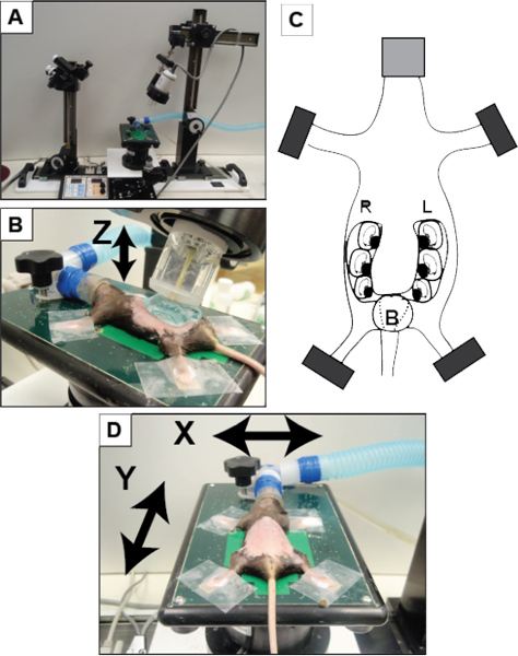
Figure 1. Overview of set-up using VisualSonics Vevo 770 system. (A) VisualSonics integrated rail system with physiological monitoring unit. (B) The mouse is positioned and properly restraint on the heating board. The four limbs are taped into the ECG electrodes. (C) Schematic of pregnant mouse and layout of embryos. The number of embryos within each horn of the uterus can vary significantly in addition to the orientation of the fetus. (D) A positioned dam on the imaging platform with arrows noting the planes of manipulation (X-axis and Y-axis) to move the dam for imaging. The Z-axis refers to movement of the transducer upward and downward (as indicated by the arrow in panel B). B, bladder; L, left; R, right.
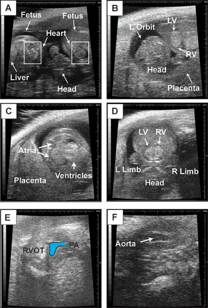
Figure 2. Representative b-mode images. This figure contains representative b-mode images of embryonic day 14.5 fetus. (A) Visualization of two neighboring fetuses. Boxes indicate location of fetal heart. (B) Anatomic landmarks in a fetus to guide orientation. Embryonic day 14.5 heart in a four-chambered view (C), short-axis view of the left and right ventricles (D), right ventricular outflow tract and pulmonary artery (PA) (E), and left ventricular outflow tact (LVOT) and aorta (F).
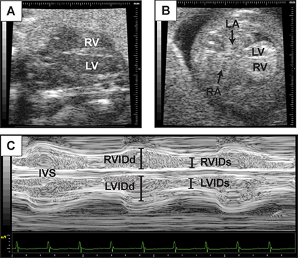
Figure 3. Representative assessment of ventricular function. This figure contains representative images of 2D echocardiography of the long axis view of the heart at embryonic day 14.5 (A), and a four-chambered view (B). (C) M-mode tracing with lines indicating left and right ventricular internal diameter at diastole (R/LVIDd) and systole (R/LVIDs) from the four chamber image plane. Interventricular septum (IVS) is also visualized.
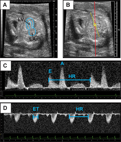
Figure 4. Representative Doppler assessment. This figure contains representative images of 2D echocardiography of embryonic day 14.5 heart in an apical four-chamber view (A). The left atrium and left ventricular cavity have been outlined. (B) Representative placement of Pulse wave Doppler sample volume for recording of mitral inflow. (C) Mitral inflow Doppler patterns from which early diastolic velocity (denoted "E") and atrial contraction (denoted "A") velocities can be measured. (D) Representative aortic Doppler waveform. Aortic Doppler jet can be used to measure ejection time (ET). Heart rate (HR) may be calculated from the measurement of one flow cycle to the following flow cycle. Click here to view larger figure.
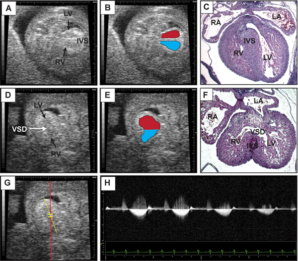
Figure 5. Representative detection of ventricular septal defect. This figure contains representative b-mode images of embryonic day 14.5 heart in an apical four-chamber view (A) with the right and left ventricular cavities outlined in (B). Note the presence of the interventricular septum. (C) Transverse section of imaged heart stained with hematoxylin and eosin. (D) B-mode image of embryonic day 14.5 heart with a ventricular sepal defect (VSD) indicated by the arrow. (E) Right and left ventricular cavities are outlined with superimposed placement of Pulse wave Doppler sample volume for recording of flow across the interventricular septum. (F) Transverse section stained with hematoxylin and eosin of imaged heart after specimen retrieval. (G) Superimposed placement of Pulse wave Doppler sample volume for recording of flow across the interventricular septum. (H) Representative Doppler tracing from (G) demonstrating flow from the left to right ventricle. Click here to view larger figure.
Access restricted. Please log in or start a trial to view this content.
Discussion
The ability to perform serial measurements and to detect mutant fetuses with cardiac defects highlights the usefulness of echocardiography for investigating normal and abnormal cardiovascular development. Analysis of cardiac structure and function in vivo has become an integral part in the description of genetic and non-genetic modifications to normal fetal development. The availability of 2D-guided Doppler makes it possible to monitor heart rate and blood flow patterns while obtaining real-time images. De...
Access restricted. Please log in or start a trial to view this content.
Disclosures
No conflicts of interest declared.
Acknowledgements
GHK is supported by NIH/NHLBI K08-HL098565 and the Institute for Cardiovascular Research at the University of Chicago. All experimental methods described are approved by the Institutional Animal Care and Use Committee at the University of Chicago.
Access restricted. Please log in or start a trial to view this content.
Materials
| Name | Company | Catalog Number | Comments |
|---|---|---|---|
| Vevo 770 Imaging System (Toronto, Canada) | VisualSonics | ||
| MHz transducer | RMV707B15-45 | ||
| Isoflurane Vaporizer | Tec 3 | ||
| Isoflurane | 2-chloro-2-(difluoromethoxy)-1,1,1-trifluoro-ethane |
References
- Wessels, A., Sedmera, D. Developmental anatomy of the heart: a tale of mice and man. Physiol. Genomics. 15, 165(2003).
- Snider, P., Conway, S. J. Probing human cardiovascular congenital disease using transgenic mouse models. Prog. Mol. Biol. Transl. Sci. 100, 83(2011).
- Clark, K. L., Yutzey, K. E., Benson, D. W. Transcription factors and congenital heart defects. Annu. Rev. Physiol. 68, 97(2006).
- Leatherbury, L., Yu, Q., Lo, C. W. Noninvasive phenotypic analysis of cardiovascular structure and function in fetal mice using ultrasound. Birth Defects Res C Embryo Today. 69, 83(2003).
- Spurney, C. F., Lo, C. W., Leatherbury, L. Fetal mouse imaging using echocardiography: a review of current technology. Echocardiography. 23, 891(2006).
- Spurney, C. F., Leatherbury, L., Lo, C. W. High-frequency ultrasound database profiling growth, development, and cardiovascular function in C57BL/6J mouse fetuses. J. Am. Soc. Echocardiogr. 17, 893(2004).
- Shen, Y., et al. Cardiovascular phenotyping of fetal mice by noninvasive high-frequency ultrasound facilitates recovery of ENU-induced mutations causing congenital cardiac and extracardiac defects. Physiol. Genomics. 24, 23(2005).
- Yu, Q., Leatherbury, L., Tian, X., Lo, C. W. Cardiovascular assessment of fetal mice by in utero echocardiography. Ultrasound Med. Biol. 34, 741(2008).
- Linask, K. K., Huhta, J. C. Use of Doppler echocardiography to monitor embryonic mouse heart function. Methods Mol. Biol. 135, 245(2000).
- Hinton, R. B., et al. Mouse heart valve structure and function: echocardiographic and morphometric analyses from the fetus through the aged adult. Am. J. Physiol Heart Circ. Physiol. 294, H2480(2008).
- Gui, Y. H., Linask, K. K., Khowsathit, P., Huhta, J. C. Doppler echocardiography of normal and abnormal embryonic mouse heart. Pediatr. Res. 40, 633(1996).
- Purssell, E., et al. Noninvasive high-resolution ultrasound reveals structural and functional deficits in dimethadione-exposed fetal rat hearts in utero. Birth Defects Res. B Dev. Reprod. Toxicol. , (2011).
- Le, V. P., Kovacs, A., Wagenseil, J. E. Measuring Left Ventricular Pressure in Late Embryonic and Neonatal Mice. J. Vis. Exp. (60), e3756(2012).
- Ji, R. P., Phoon, C. K. Noninvasive localization of nuclear factor of activated T cells c1-/- mouse embryos by ultrasound biomicroscopy-Doppler allows genotype-phenotype correlation. J. Am. Soc. Echocardiogr. 18, 1415(2005).
- Kim, G. H., Samant, S. A., Earley, J. U., Svensson, E. C. Translational control of FOG-2 expression in cardiomyocytes by microRNA-130a. PLoS One. 4, e6161(2009).
- Momoi, N., et al. Modest maternal caffeine exposure affects developing embryonic cardiovascular function and growth. Am. J. Physiol. Heart Circ. Physiol. 294, H2248(2008).
- Tobita, K., Liu, X., Lo, C. W. Imaging modalities to assess structural birth defects in mutant mouse models. Birth Defects Res. C Embryo Today. 90, 176(2010).
Access restricted. Please log in or start a trial to view this content.
Reprints and Permissions
