Radiation therapy is a highly complex cancer treatment that requires multiple specialists to create a treatment plan and provide quality assurance (QA) prior to delivery to a patient. This protocol describes the use of a fully automated system, the Radiation Planning Assistant (RPA), to create high-quality radiation treatment plans.
Method Article
Radiation Planning Assistant - A Streamlined, Fully Automated Radiotherapy Treatment Planning System
In This Article
Summary
Abstract
The Radiation Planning Assistant (RPA) is a system developed for the fully automated creation of radiotherapy treatment plans, including volume-modulated arc therapy (VMAT) plans for patients with head/neck cancer and 4-field box plans for patients with cervical cancer. It is a combination of specially developed in-house software that uses an application programming interface to communicate with a commercial radiotherapy treatment planning system. It also interfaces with a commercial secondary dose verification software. The necessary inputs to the system are a Treatment Plan Order, approved by the radiation oncologist, and a simulation computed tomography (CT) image, approved by the radiographer. The RPA then generates a complete radiotherapy treatment plan. For the cervical cancer treatment plans, no additional user intervention is necessary until the plan is complete. For head/neck treatment plans, after the normal tissue and some of the target structures are automatically delineated on the CT image, the radiation oncologist must review the contours, making edits if necessary. They also delineate the gross tumor volume. The RPA then completes the treatment planning process, creating a VMAT plan. Finally, the completed plan must be reviewed by qualified clinical staff.
Introduction
In radiotherapy clinics, the International Atomic Energy Agency (IAEA) recommends 1 treatment planner per 300 patients, and 1 radiation physicist per 400 patients treated annually1. In many countries, these roles (treatment planner and physicist) are combined. In other countries, the radiation therapy technologists (often called radiographers) also take on a treatment planning role. Low- and middle-income countries (LMICs) have serious deficits in radiation oncologists, medical physicists and radiation therapy technologists. By 2020, it is estimated that we will need an additional 12,000 radiation oncologists, 10,000 medical physicists, and 29,000 technologists.2. These estimates are based on data from various data sets in the public domain (e.g., IAEA), with staffing levels based on recommendations from the European Society for Radiotherapy & Oncology (ESTRO) and IAEA3. The training needs are immense. For example, for medical physicists, most guidelines recommend a 2- to 3-year internship or residency, often after completion of medical physics graduate school4,5,6. This 4-year commitment means that 40,000 man-years of training are needed just to address the global deficiency in medical physicists alone.
Automation of treatment planning could reduce some of these staffing deficiencies, particularly medical physicists and planning staff. Automated planning could reduce the time that radiation oncologists spend on treatment planning3 and certainly have important roles in drawing radiation treatment beam apertures. This work describes the operation of a fully automated treatment planning system, the Radiation Planning Assistant (RPA), developed under a project funded by the National Cancer Institute to ultimately improve access to high quality radiotherapy across the world7.
Figure 1 shows an overview of the automated treatment planning process implemented in the RPA. The treatment planning tasks are performed using either functions in the treatment planning system (see the Table of Materials for the planning system used), controlled using the application programming interface (API), or using in-house developed functions. A key component of the RPA is the independent verification of all tasks that have been automated8. This is achieved using a second, different set of algorithms/functions. The results of the primary algorithms, which are used for the treatment plan, are compared with the results of the secondary algorithm, and flagged if the difference is larger than a pre-determined criteria9. Treatment plans that pass the independent checks and further manual checks by local staff are ready to be used for the patient treatment. The output documentation of the RPA has been specifically designed to streamline the manual check process.
The workflow of the RPA system from the users' point of view is shown in Figure 2. The inputs to the system are an approved plan order and an approved CT image. The radiation oncologist creates and approves the plan order containing basic patient information and details about the expected plan (prescription, treatment type, etc.). The CT image set must also be approved (by the CT technician). This is to ensure that the plan is calculated on the correct CT image. This is important, for example, when multiple CT image sets are taken of a single patient. Once the RPA receives an approved plan order and an approved CT image set, the treatment plan is automatically generated. In some cases, such as when creating 4-field box cervical cancer treatments, the following steps are fully automated, and no additional user intervention is needed until the treatment plan is ready. In other cases, such as the creation of head/neck VMAT treatment plans, intervention is needed halfway through the automated treatment process. For head/neck plans, the radiation oncologist is required to review/edit automatically generated contours. They also need to delineate the gross tumor volume (GTV). In this situation, after receiving approved plan orders and CTs, the RPA performs some initial contouring tasks, including contouring of normal tissues and some targets. The radiation oncologist then reviews and approves the contours, and the RPA continues with the remaining treatment planning tasks. The current system has been tested with 6 MV and 18 MV X-ray beams for head/neck and cervix treatment plans, respectively, both with flattening filter. Once the treatment plan is complete, a document is created for review and approval by the appropriate clinical staff, e.g., physicists and radiation oncologists. Some of these tasks can be delegated to other staff.
Modern treatment planning systems already offer some automated planning processes. The RPA integrates these, whenever possible, offering a complete automated planning process, such that the user can generate treatment plans without the need to open a complicated treatment planning system interface. This manuscript described the protocol for the RPA, and then presents some example results for the output of the treatment planning process.
Protocol
All patient data used for evaluating the RPA were used retrospectively, with approval from the University of Texas MD Anderson Institutional Review Board.
1. Monitoring Planning Progress
- Open the Radiation Planning Assistant Control Center Workspace and log in.
- To see all patient data that is currently active, click All Patients.
- To find a patient by their Medical Record Number (MRN), click on Select Patient.
- To see the status of the plan for any patient who has an approved CT or approved Plan Order (or both), look in the RPA Plan section. The status options are summarized immediately above this section, and in the Message section.
- To review details of any completed plan, click the patient (in the RPA section). Details of their plan order and CT can also be seen in the Plan Order and CT Approval sections.
- To approve a completed plan, click on Approve. There are certain levels of approval (physician, physicist, and technician) that can be set for each institution.
- To review the task history of the RPA, click on log.
- To review details for any plan order (including ones that have not yet been approved), click on a patient in the Plan Order section.
- To review details for any CT image set (including ones that have not yet been approved), click on a patient in the CT Approval section.
2. Plan Order Approval
NOTE: Plan order approval (typically by the radiation oncologist) is required before the RPA creates a treatment plan.
- Open the Plan Order workspace. Use the standalone icon, or do this from the Radiation Planning Assistant Control Center workspace.
- Create a new plan order as follows.
- Click New.
- Complete Section 1 - Demographics; this section is always the same.
- Enter the medical record number and patient name.
- Select the appropriate treatment site. Choose from head/neck, cervix, breast, and others.
NOTE: This list will increase as our development efforts progress. This selection changes the choices offered in Section 3, below.
- Complete Section 2 - General Treatment; this section is always the same.
- Complete the questions on sex/pregnancy status, prior irradiation, pacemaker, and other implants.
- Complete the question on Autostart or Technician.
NOTE: Selecting autostart will result in the RPA automatically starting the planning process when there are both an approved Plan Order and an approved CT image. Selecting Technician will require a technician to start the automatic planning process. This can be done in the Control Center Workspace.
- Complete Section 3 - Treatment Specific.
NOTE: This example is for head/neck treatments.- Select the head/neck primary site and positive lymph involvement by selecting the appropriate radio button; the following sections are automatically selected based on these choices.
- Confirm or change the sections on cervical neck and retropharyngeal lymph node coverage, by selecting the appropriate radio button. Then select the appropriate radio button to indicate whether these correspond to CTV1 or CTV2 (CTV: Clinical Target Volume).
- Select treatment machine and treatment technique.
- Select the treatment approach by clicking on the appropriate radio button (this example is for VMAT treatments).
- Confirm or change the treatment prescription. To change the prescription, enter the required fraction doses into the text boxes.
- Confirm the appropriateness of the normal tissue dose constraints.
- Save the Plan Order; a pdf of the plan order will be generated.
- Review the final plan order.
- If the final plan order is correct, click on Approve.
- If the final Plan Order is incorrect, click on Edit and make changes as necessary.
- Close the Plan Order workspace.
3. CT Image Approval
NOTE: CT approval is required before the RPA creates a treatment plan.
- Open the CT Approval workspace.
NOTE: This can be done from the standalone icon, or from the Radiation Planning Assistant Control Center workspace. - Click on the CT scan that it to be approved.
NOTE: If the CT scan does not show up, it has not been received by the RPA. - Review the CT slices centered on the isocenter.
- Click on Load All to review all CT images.
- Review isocenter location and CT image quality.
- If the CT images, number of slices, orientation and data are correct, click on Approve.
4. Initiate Automatic Treatment Planning
NOTE: This step is only needed if Autoplan start (in the plan order) is set to Technician.
- Select the correct patient/Plan Order/CT in the Control Center workspace, and click Add RPA Plan.
5. Contouring Review and Approval
NOTE: For some treatments, such as head/neck VMAT, contouring review and approval is required. This is typically performed by the radiation oncologist.
- Wait for the patient data status to indicate W (wait) in the control center; it is now ready for contouring review.
- Click on the W icon, or on ROI Approval (ROI: Region-of-Interest). Note that the Contouring Review and Approval workspace will open.
NOTE: The contours that are available here depend on the type of plan to be generated (selected in the Plan Order). - Review all contoured tissues/targets. To edit structures, first select the structure of interest (pulldown list), then click on the Nudge icon and edit the contour on each CT slice.
- If necessary (e.g., for head/neck plans), manually delineate the Gross Tumor Volume (GTV) and positive lymph nodes. To do this, select the structure of interest (e.g., GTV) from the pulldown list, click on the manual delineation icon, and draw the structure on each CT slice.
- Create Clinical Target Volume (CTV1) (for head/neck cases)
- To expand the GTV and positive lymph nodes, click on GTV->CTV.
- To manually draw CTV1, select CTV1 from the list of structures (pulldown list), click on the manual delineation icon, and draw the structure on each CT slice.
- Review and edit CTV1, as necessary.
- Create Planning Target Volumes (PTVs).
- Click on CTV->PTV. Review.
- Edit if necessary, but remember these expansions account for the many uncertainties in both contouring and patient setup. To edit the PTV, select the appropriate PTV from the pulldown list, click on the Nudge icon (or one of the other editing icons),
- Approve contours.
- Review all contours then click on Approve ROI. Once the ROIs are approved, the treatment planning process will proceed automatically. Pay attention to any warning messages and add explanatory notes, as necessary.
6. Radiotherapy Plan Review and Approval
- Review the treatment plan when it is ready for review; it appears as a Plan Review Document (pdf format) in the Control Center.
NOTE: The plan can be reviewed in stages (which can be combined, depending on available staff). The appropriate review stage is shown in the footer of each page. - Perform Technical Review.
NOTE: This can be combined with the Physics Review.- Review the front page.
- Review and ensure that the patient demographics, prescription and plan details are appropriate.
- Check that all the automatic plan verification checks were successful.
- Check the marked isocenter.
- Answer the questions on the form to check that the marked isocenter was correctly identified. Compare with the library cases, as necessary.
- Perform Body Contour Review.
- Answer the questions to check that the body was correctly contoured. Compare with the library cases, as necessary.
- Perform Field Aperture Review.
- Answer the questions on the form to check that the field apertures are appropriate.
- Perform Dose Distribution Review.
- Answer the questions on the form to check for appropriate dose calculation
- To approve or reject this plan, click on Tech. Approve.
- Review the front page.
- Perform the Physician Review.
- Depending on the treatment type, review the dose distributions and field apertures.
- To change the approval status of this plan to approve or reject, click on MD Approve.
- Perform Physics Review.
- Review the plan using standard procedures. See the following guidelines for supplemental checks.
- Review the Physician Review and Technical Review Sections.
- Review the results of the independent verification QA: table removal, body contour check, isocenter check.
- Review the results of additional independent verification checks that are specific to the treatment site - for example, the block check for 4-field cervix treatments.
- Review the results of the comparisons of the field and plan parameters with those from the patient population.
- Review the dose verification report.
- Review additional data. Additional data at the end of the document should be reviewed for consistency - this includes the original Plan Order and CT Approval.
- To change the approval status of this plan to Approve or Reject, click on Physics Approve.
7. Final Plan Transfer
- Once the plan is approved, export it. The next steps are dependent on the local setup, record-and-verify software and treatment planning system. They are also dependent on ethics protocols and local clinical workflow. The following are steps are examples of appropriate steps.
- Transfer DICOM plan to local record-and-verify (R&V) system.
- Use a software tool to compare the original plan with that in the R&V system (to verify correct data transfer).
Results
An example Treatment Plan Order created for a head/neck case is shown in Figure 3. Figure 4 shows the dose distribution for an automatically generated VMAT plan for a patient with a base of tongue squamous cell carcinoma7,10. A review by an attending radiation oncologist confirmed that this plan was acceptable for treatment. On average the head/neck VMAT plans take 46 minutes for a 2-arc plan, and we expect to bring this down to less than 30 minutes with a faster dose calculation algorithm and a distributed architecture for the automated contouring step.
Figure 5 shows automatically generated field apertures for a 4-field box treatment for a patient with cervical cancer. Review by an experienced radiation oncologist confirmed the clinical appropriateness of 90-96% of these fields7,11. On average, these plans took 21 minutes.
Once the treatment plan is ready, documentation is automatically created for review by radiation oncologists, technical staff, medical physicists, and radiographers. We have designed an illustrated procedure that leads the user through checks of marked isocenter and body contour identification, consistency of patient orientation/laterality/treatment site, field apertures (for a 4-field box example), and presence of image or dose calculation artifacts12. Each step of the procedure has simple instructions and library examples to which the user can refer. An example of the instructions is shown in Figure 6.
Although the need for physics and radiation oncologist review is well documented, the role of additional staff has not been evaluated. We assessed this by creating plan documents for 16 cervical cancer patients, 12 of which included intentional errors: incorrect isocenter (3 cases), incorrect body contour (3 cases), incorrect CT couch removal (1 case), incorrect field apertures (5 cases), incorrect dose calculation (1 case), and incorrect number of fields (1 case). These plans were then reviewed by 4 volunteers with minimal experience in radiotherapy and no experience in checking plans. The final version of the plan documentation required ~30 minutes of training. On average, plan checks required 8 minutes per plan. The testers were able to find all errors in the body contours, isocenter (based on fiducial markers) and dose calculation artifacts. They were not able to reliably identify small (but clinically important) errors in the field apertures. They were also not able to identify the case that had only 3 fields instead of 4 - an example of an unanticipated error that is not examined with a specific check-list item. In summary, these results indicate that initial checking of some vital features of radiotherapy plans created by automated processes may be assigned to staff with limited radiotherapy experience, allowing any need for remedial action to be identified before physician review. These staff will not, however, find all errors and additional checks by qualified staff (radiation oncologists and physicists) are still a vital part of the radiotherapy planning workflow.

Figure 1. Schematic of the automated treatment planning process. The human icons show the points in the workflow where human intervention is necessary. All other steps are automated. Each automated step in the planning process has a primary algorithm, which is used to create the actual plan, and a secondary algorithm that is used to verify the result of the primary algorithm. If any of the verification checks fail (i.e. fall outside a predetermined criteria), or if the radiation oncologist does not approve the plan, then a manual planning process becomes necessary. Additional quality procedures that are important to the treatment planning process, specifically routine checks by a qualified medical physicist, are not shown here. Please click here to view a larger version of this figure.
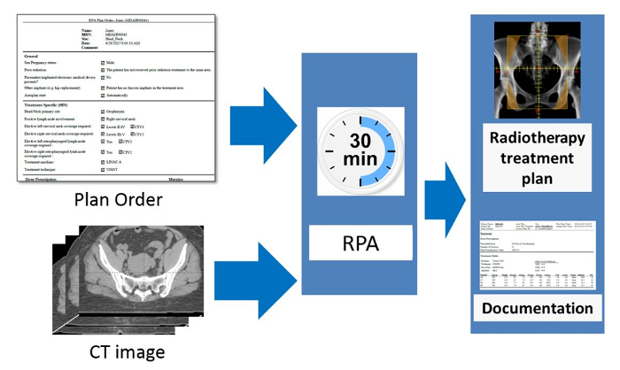
Figure 2. Schematic of the RPA from the users' point of view. The radiation oncologist is responsible for completing and approving the Physician's Plan Order. After taking the simulation image of the patient, this is approved by the radiographer or other appropriate staff present. The RPA then automatically starts and creates the radiotherapy treatment plan. The goal of this work is to create each radiotherapy plan, including documentation, within 30 minutes. Please click here to view a larger version of this figure.
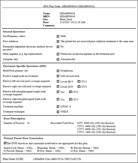
Figure 3 An example Treatment Plan Order for a head/neck VMAT plan. The Plan Order shows the patient identifiers (name, MRN, etc.), some general information about the patient, and some treatment specific information. This includes the dose prescription, target coverage and normal tissue constraints.
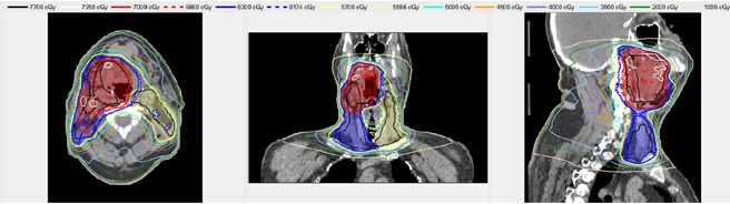
Figure 4. An example automatically generated head/neck VMAT plan. The shaded regions show the Planning Target Volumes - red, blue and yellow correspond to PTV1 PTV2, and PTV3, respectively. The lines show the isodose distribution of the automatically generated plan.
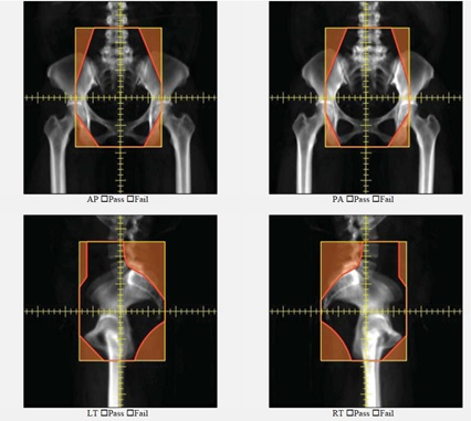
Figure 5. An example of automatically generated apertures for a 4-field box cervical cancer treatment. AP, PA, left lateral and right lateral fields are shown.

Figure 6. Example of the illustrated instructions designed to aid chart review for radiotherapy plans automatically generated using the RPA. This example page is for the review of the automatically generated body contour. It includes the results of the primary algorithm, some questions for the user, and a library case for the user to review
Discussion
A protocol outlining the steps in creating an automated treatment plan using the Radiation Planning Assistant (RPA) system was described. The crucial steps, from a user's point of view, are (1) CT approval (2) Plan Order Approval (3) Contour review/editing for head/neck cases, and (4) Treatment Plan review. The order of the first two steps is interchangeable. The Radiation Planning Assistant currently automatically creates radiotherapy plans for head/neck (VMAT) and cervical cancer (4-field box), and we are currently working on plans for breast cancer treatments. The final goal is to fully automate radiotherapy treatment planning for all sites/modalities, creating a tool that generates safe and effective radiotherapy treatment plans.
The current system has several limitations. First, it cannot create treatment plans for all treatment sites and approaches, although we expect its capabilities to improve over time, we are some way away from full automation for all treatment sites. There is also a risk of over reliance by the users on automation - this is a risk that we have attempted to mitigate by including many independent verification checks (Figure 1). It was demonstrated that the use of our purpose-developed plan documentation to check treatment plans will enable some potential errors to be identified by relatively inexperienced staff, but review by the radiation oncologist, and plan checks by other qualified staff are important.
We expect to improve the RPA interfaces over time, in response to user feedback. The general workflow and tasks should, however, remain similar to those described in this document. This document should, therefore, continue to be useful. Additional documentation will also be available, describing any modifications, training for plan checks, etc.
There are existing examples of automation of specific steps of the radiotherapy treatment planning. To our knowledge this is the first system for which the entire workflow is fully automated, requiring almost no input from the user. This protocol describes, from the user's point of view, the important steps needed to operate the Radiation Planning Assistant, and generate a radiotherapy treatment plan.
Disclosures
The authors have nothing to disclose.
Acknowledgements
This work was funded by the National Cancer Institute, with additional support by Varian Medical Systems and Mobius Medical Systems. Our current system uses Eclipse for treatment planning functions, and Mobius 3D for verification of dose calculation.
Materials
| Name | Company | Catalog Number | Comments |
|---|---|---|---|
| Eclipse | Varian Medical Systems | na | Treatment planning system |
| Mobius 3D | Mobius Medical Systems | na | Dose calculation verification system |
References
- IAEA. Planning National Radiotherapy Services: A Practical Tool IAEA. , IAEA. Vienna. (2010).
- Datta, N. R., Samiei, M., Bodis, S. Radiation Therapy Infrastructure and Human Resources in Low- and Middle-Income Countries: Present Status and Projections for 2020. International Journal of Radiation Oncology*Biology*Physics. 89 (3), 448-457 (2014).
- Slotman, B. J., et al. Overview of national guidelines for infrastructure and staffing of radiotherapy. ESTRO-QUARTS: work package 1. Radiotherapy and Oncology. 75 (3), 349-354 (2005).
- International Organization for Medical Physics. Policy Statement No 2: Basic Requirements for Education and Training of Medical Physicists. , (2010).
- Commission on Accreditation of Medical Physics Educational Programs, Inc . Standards for Accreditation of Residency Educational Programs in Medical Physics. , http://www.campep.org/ResidencyStandards.pdf (2014).
- Caruana, C. J., Christofides, S., Hartmann, G. H. European Federation of Organisations for Medical Physics (EFOMP) Policy Statement 12.1: Recommendations on Medical Physics Education and Training in Europe 2014. Physica Medica. 30 (6), 598-603 (2014).
- Kisling, K., et al. SU-F-T-423: Automating Treatment Planning for Cervical Cancer in Low- and Middle- Income Countries. Medical Physics. 43 (6Part19), 3560-3560 (2016).
- McCarroll, R., et al. TU-H-CAMPUS-JeP1-02: Fully Automatic Verification of Automatically Contoured Normal Tissues in the Head and Neck. Medical Physics. 43 (6Part37), 3778-3778 (2016).
- McCarroll, R., et al. Machine Learning for the Prediction of Physician Edits to Clinical Auto-Contours in the Head-And-Neck. American Association of Physicists in Medicine Annual Meeting. , (2017).
- McCarroll, R., et al. Fully Automated VMAT Planning in the Head and Neck. American Association of Physicists in Medicine Annual Meeting. , (2017).
- Kisling, K., et al. Fully-Automated Treatment Planning for Cervical Cancer Radiotherapy. American Association of Physicists in Medicine Annual Meeting. , (2017).
- Court, L., et al. An Initial Plan Check Procedure Specifically Designed for Fully-Automated Treatment Planning. American Association of Physicists in Medicine Annual Meeting. , (2017).
Reprints and Permissions
