Spontaneous Chemical Reactions
Spontaneous redox reactions occur abundantly in nature. The chemical reaction occurring in a disposable AA battery powering our remote controls is one such example of a spontaneous redox reaction. Another example is the immersion of coiled copper wire into an aqueous silver nitrate solution. The reaction shows a gradual, visually impressive color change from colorless to bright blue and the formation of a grey precipitate on the copper wire. In this experiment, the copper undergoes oxidation to form cuprous ions, which renders the solution blue, while the silver ions are reduced to form a silver precipitate on the wire.
The reaction can be summarized as follows:

Here, there is a direct and spontaneous transfer of electrons from the copper wire to the aqueous silver ions.
Electrochemical Cells and Galvanic Cells
Suppose a device contains all the reactants and products of a redox system but prevents physical contact between the reactants. Therefore, the direct transfer of electrons is prevented; instead, it takes place indirectly through an external circuit that contacts the separated reactants. Devices of this type are generally referred to as electrochemical cells.
An electrochemical cell is an instrument in which an electric current is generated by a redox reaction without direct contact between the reacting atoms. The electrochemical cells in which a current is created due to a spontaneous redox reaction are known as galvanic or voltaic cells (named after Luigi Galvani and Alessandro Volta).
Components of a Galvanic Cell
A galvanic cell based on the spontaneous reaction between copper and silver(I) is depicted in Figure 1. A typical galvanic cell consists of two half-cells, each containing a redox conjugate pair, or couple, of a single reactant. The half-cell on the left contains the Cu(0)/Cu(II) couple in the form of a solid copper foil and an aqueous solution of copper nitrate. The right half-cell contains the Ag(I)/Ag(0) couple as solid silver foil and an aqueous silver nitrate solution. An external circuit is connected to each half-cell at its solid foil, meaning the Cu and Ag foil each function as an electrode. The reaction occurs at the interface between each half-cell reaction mixture and its respective electrode. The anode is the electrode at which oxidation occurs and it carries a negative charge, while the cathode is the electrode at which reduction occurs, and it bears a positive charge.
The two half-cells are connected by a salt bridge, which is an inverted U-tube containing a gel or paste of an inert electrolyte like potassium chloride or ammonium nitrate. The salt bridge helps to keep the reaction mixtures separate while ensuring the reaction’s charge balance. The spontaneous reaction in this cell produces Cu2+ cations in the anode half-cell and consumes Ag+ ions in the cathode half-cell, resulting in a compensatory flow of inert ions from the salt bridge that maintains charge balance. The salt bridge provides a flow of inert ions, ensuring that the reaction continues by neutralizing the buildup of positive and negative ions at the anode and cathode. Hence, increasing concentrations of Cu2+ in the anode half-cell are balanced by an influx of NO3− from the salt bridge, while a flow of Na+ into the cathode half-cell compensates for the decreasing Ag+ concentration.
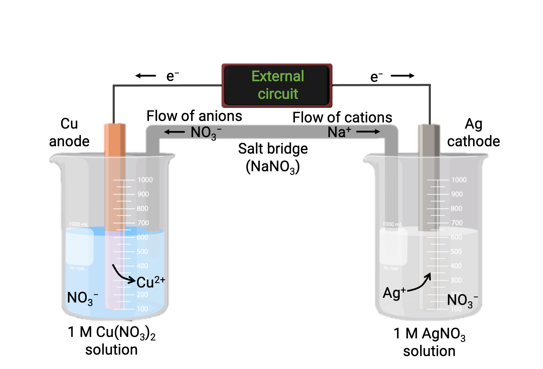
Figure 1: A galvanic cell based on the spontaneous reaction between copper and silver(I) ions.
Representation of a Galvanic Cell using Cell Schematics or Cell Notations
The galvanic cell is represented symbolically using cell schematics or cell notations.
• In cell schematics, all interfaces between the component phases are represented by vertical parallel lines.
• If two or more components exist in the same phase, they are separated in the representation using commas.
• The anode is represented at the left of the schematic and the cathode to the right.
• A double vertical line indicates a salt bridge or a porous partition between the two half-reactions.
• By convention, the schematic begins with the anode and proceeds left-to-right, identifying phases and interfaces encountered within the cell, ending with the cathode.
For example, the above galvanic cell consists of a solid copper anode immersed in an aqueous copper(II) nitrate connected via a salt bridge to an aqueous silver(I) nitrate solution immersed in which is a solid silver cathode. Converting this statement to symbolism following the above guidelines results in the cell schematic:

This text is adapted from Openstax, Chemistry 2e,17.2 Galvanic Cells.