Targeted-esterase induced dye loading (TED) supports the analysis of intracellular calcium store dynamics by fluorescence imaging. The method bases on targeting of a recombinant Carboxylesterase to the endoplasmic reticulum (ER), where it improves the local unmasking of synthetic low-affinity Ca2+ indicator dyes in the ER lumen.
Method Article
Direct Imaging of ER Calcium with Targeted-Esterase Induced Dye Loading (TED)
In This Article
Summary
Abstract
Visualization of calcium dynamics is important to understand the role of calcium in cell physiology. To examine calcium dynamics, synthetic fluorescent Ca2+ indictors have become popular. Here we demonstrate TED (= targeted-esterase induced dye loading), a method to improve the release of Ca2+ indicator dyes in the ER lumen of different cell types. To date, TED was used in cell lines, glial cells, and neurons in vitro. TED bases on efficient, recombinant targeting of a high carboxylesterase activity to the ER lumen using vector-constructs that express Carboxylesterases (CES). The latest TED vectors contain a core element of CES2 fused to a red fluorescent protein, thus enabling simultaneous two-color imaging. The dynamics of free calcium in the ER are imaged in one color, while the corresponding ER structure appears in red. At the beginning of the procedure, cells are transduced with a lentivirus. Subsequently, the infected cells are seeded on coverslips to finally enable live cell imaging. Then, living cells are incubated with the acetoxymethyl ester (AM-ester) form of low-affinity Ca2+ indicators, for instance Fluo5N-AM, Mag-Fluo4-AM, or Mag-Fura2-AM. The esterase activity in the ER cleaves off hydrophobic side chains from the AM form of the Ca2+ indicator and a hydrophilic fluorescent dye/Ca2+ complex is formed and trapped in the ER lumen. After dye loading, the cells are analyzed at an inverted confocal laser scanning microscope. Cells are continuously perfused with Ringer-like solutions and the ER calcium dynamics are directly visualized by time-lapse imaging. Calcium release from the ER is identified by a decrease in fluorescence intensity in regions of interest, whereas the refilling of the ER calcium store produces an increase in fluorescence intensity. Finally, the change in fluorescent intensity over time is determined by calculation of ΔF/F0.
Introduction
In order to resolve physiological calcium responses of the ER, we developed a new strategy to improve the trapping of synthetic calcium sensitive dyes into the ER. The method enables the direct, non-disruptive real-time monitoring of free ER calcium in presence of extracellular calcium.
Function and signaling of ER Calcium
Calcium signals are found in different cell types, e.g. muscle-cells, neurons and glial cells and their functions range from mediating muscle contraction to an involvement in synaptic transmission in learning and memory 1,2. Changes in free calcium concentration are of high scientific interest because calcium is involved in the regulation of gene transcription, cell proliferation, neuronal excitability, cell death and other cell signaling events 1-7. All these cellular calcium signals are functionally connected and contribute to intracellular calcium store dynamics 8-10.
A common feature among all calcium signals is the flow of calcium between the extracellular space, the cytosol and organelles, mainly the ER and mitochondria. This causes dynamic changes in calcium concentration within these organelles, which are sensed by different signaling components. In general, the calcium concentration in the ER ranges between 100 to 800 μM, in the cytosol the calcium concentration is close to 100 nM, and in the extracellular space the concentration is around 1-2 mM. Accordingly, there is a high chemical driving force for calcium flow towards the cytosol 2,9,10.
The most commonly investigated ER-derived calcium signals depend on the stimulation of G-protein coupled receptors (GpcR), which then activate phospholipase C (PLC). PLC in turn produces inositol 1,4,5-trisphosphate (IP3) 1. Upon binding of IP3 to its receptor (IP3-Rec, Figure 1) in the ER-membrane, calcium ions are released from the ER lumen. Historically, IP3-mediated calcium release from the ER was first - even though indirectly - measured in acinar pancreatic cells by Streb et al. in 1983 11. This publication suggested for the first time a signaling cascade involving acetylcholine, phospholipase C, and IP3. This way of calcium release is generally termed IP3-induced calcium release (IiCR) (Figure 1). Kinase-dependent activation of phospholipase Cγ by receptor tyrosin kinases links the action of growth factors and neurotrophic factors to ER calcium signaling after IP3 elevation 12. In addition to IiCR, calcium elevation may be mediated by ionotropic calcium entry, for instance via voltage-gated calcium channels (CaV), and subsequent calcium-induced calcium release (CiCR) by ryanodine receptors (RyR). IiCR and CiCR are physiologically linked to store-operated calcium entry (SOCE). SOCE includes the action of STIM (stroma interacting molecule), which is a sensor for ER calcium release. STIM has been shown to stimulate extracellular calcium entry through transient receptor potential channels (Trp) 13, Orai calcium channels 14 and even voltage-gated calcium channels 15 (Figure 1) . Loss of ER calcium is dynamically rescued by the action of the sarco-endoplasmic reticulum calcium ATPase (SERCA), which actively pumps calcium back into the ER. Blocking the SERCA with drugs such as thapsigargin unveils a continuous loss of ER calcium to the cytosolic compartment. This ER calcium "leak" is caused by ER intramembrane pore complexes such as the Sec61 protein complex 16,17 (Figure 1).
In 1998, Berridge published a model, the "neuron within a neuron model", which suggests a principle physiological role of the ER in integrating neuronal calcium 5. This model considers the existence of a continuous ER membrane system forming an intracellular "image" of the neuronal plasma membrane 5. This binary eukaryotic membrane system was claimed to be a basic prerequisite for temporal and spatial integration of fast and slow calcium signals in neurons. Calcium signals that occur either concomitantly or subsequently in different spines or dendrites of the same neuron are conferred to the cell's soma or nucleus via the ER, where they are summed up 5,18. Then, their sum may have effects on the excitability of the neuron, regulation of gene transcription or integration of signaling cascades. Thus, the ER supports the integration of calcium signals. One prerequisite for this concept is the continuity of the ER in a single cell, which has been claimed by several studies and which has been proven at least for somato-dendritic areas and short distance axonal projections 19-21. Whether there is ER continuity within long axonal projections is a matter of debate.
Strategies to measure the flow of free calcium over the ER membrane
Calcium signals are most frequently monitored in the cytosol 22,23. Therefore, it cannot easily be distinguished whether Ca2+ is flowing into the cytosol from extracellular or from intracellular stores 6,24. To overcome this limitation, methodological strategies for direct ER calcium imaging have been developed. In summary, the following strategies are used: (1) ER-targeted genetically engineered protein-indicators 25-27. Protein-based low-affinity Ca2+ indicators use the bioluminescent protein aequorin or GFP in combination with a calcium sensing protein. These genetically engineered Ca2+ indicators (GECIs) can be targeted to the ER with the help of a signal peptide and are actively kept in the ER using a retention and retrieval motif. Common ER Ca2+ indicators base on the Cameleon principle and are the Cameleon YC4.3 26,28; Cameleon split YC7.3ER 29, and Cameleon D1 30. (2) Direct esterase-based dye loading of AM-ester low-affinity Ca2+ indicators 31,32. AM-derivatives of the indicator dyes (Mag-Fura2-AM, Mag-Fluo4-AM or Fluo5N-AM) pass the biological membranes in a lipophilic, calcium-insensitive state. Then, in the cytosol as well as in the ER, endogenous esterases cleave of the AM-ester group and release the Ca2+ indicator, leaving behind a certain amount of active dye in the cytosol and in the ER. Therefore, this approach is useful under conditions of a high calcium concentration in the ER as long as the cytosolic calcium concentration stays well below the detection limit of the low-affinity indicators, particularly during characteristic calcium signals (e.g. nM to low μM). (3) AM-ester loading in combination with plasma membrane permeabilization 32. Any remaining cytosolic Ca2+ indicator is removed by plasma membrane permeabilization with small amounts of a "mild" detergent (e.g. saponin) in an artificial intracellular buffer. Thus, the intracellular membranes may be stimulated, e.g. with IP3 in the intracellular buffer, directly through "pores" in the plasma membrane. (4) Dialysis of the cytosol under whole-cell configuration and simultaneous measurements of Ca2+ in the ER lumen and the cytosol 32,33. A cell is first loaded with a low-affinity Ca2+ indicator (e.g. Mag-Fura2-AM, ratiometric, UV-light). Afterwards, with the help of a patch pipette, any remaining cytosolic low-affinity Ca2+ indicator is dialysed out of the cytosol with a buffer containing a high-affinity Ca2+ indicator (e.g. Fluo-3, visible light). This strategy enables the simultaneous recording of cytosolic and ER derived signals. (5) Targeted-esterase-induced dye loading 8,34. A Carboxylesterase (CES) is targeted to the lumen of the ER and provides a high esterase activity for efficient trapping of the AM-ester form of low-affinity Ca2+ indicators.
Targeted-esterase induced dye loading (TED)
To improve targeting of low-affinity Ca2+ indicators to the ER lumen, TED was developed. TED requires the overexpression of an ER targeted mouse carboxylesterase (CES2) (Figure 2), which is achieved via expression constructs. Cells expressing a recombinant CES-construct are incubated with the AM-ester form of a calcium indicator dye (Fluo5N-AM, Figure 2). Then, in the ER, the dye is converted to the Ca2+ sensitive, membrane impermeable Ca2+ indicator complex (Fluo5N/Ca2+) by the high esterase activity, therefore trapping the dye in a high concentration in the ER lumen 8,34. The method is especially useful to investigate ER calcium-release via the IiCR-pathways for instance via metabotropic, purinergic- or glutamate receptors 8,34 and to visualize ER calcium depletion via "leak channels" directly, for instance after blockade of the SERCA 17,34. To our experience the low-affinity Ca2+ indicator Fluo5N-AM is currently the best available indicator to use with the TED dye loading strategy. Fluo5N-AM has a low-affinity for Ca2+ (dissociation constant KD ~90 μM, Figure 2), is almost non-fluorescent in its AM-form, but provides high fluorescence emission upon calcium binding 8,34. The Fluo5N/Ca2+ complex can be excited with a standard light source of ~490 nm, which corresponds to standard dyes such as FITC, Alexa 488, or eGFP. Cytosolic calcium signals scarcely reach a concentration in the low μM range and are therefore barely detected by Fluo5N in the cytosol 35.
To improve the TED performance, several recombinant vector constructs were developed (Figure 3). Originally, TED vectors based on the coding sequence of CES2 (Refseq accession number NM_145603, CES2c) and best TED performance is observed with stable expression of CES constructs. New TED vectors express a core element of CES2 fused to the red fluorescence protein TagRFP-T2 36. These vectors have the advantage that they can be used to identify transduced cells and to use the red fluorescence as an internal control for the normalization of changes in Fluo5N/Ca2+ fluorescence. The red fluorescence also offers the possibility to visualize the structural distribution of the ER and changes in ER dynamics under stimulation conditions.
Protocol
This protocol introduces TED applied to cell lines, hippocampal neurons and cortical glial cells. TED performance is best when TED vectors are stably expressed, for instance by lentiviral vectors. A schematic overview of the TED method is shown in Figure 4.
1. Preparation of Solutions
The following solutions should be prepared before starting and can be stored as indicated. We generally use sterilized glass and plastic material and autoclaved water.
- Prepare HEPES-Ringer (in mM): 125 NaCl, 3 KCl, 25 HEPES, 2 MgSO4.7H2O, 2 CaCl2, 1.25 NaH2PO4.H2O, 10 glucose.H2O. Calcium-free HEPES-Ringer consists of (in mM): 127 NaCl, 3 KCl, 25 HEPES, 2 MgSO4.7H2O, 1.25 NaH2PO4.H2O, 10 glucose.H2O and 0.1 EGTA. Without glucose these imaging solutions can be stored at 4 °C. The required amount of D-glucose is freshly added before use.
- For TED analysis in hippocampal neurons, artificial cerebrospinal fluid (ACSF) is recommended. ACSF is composed of (in mM): 127 NaCl, 23 NaHCO3, 3 KCl, 2.5 NaHPO4.H2O, 25 D-glucose.H2O, 2 CaCl2, 2 MgCl2.7 H20 in ddH20.
- Prepare Fluo5N-AM to a concentration of 5 mM. To help solubilization add 8.9 μl of 20% Pluronic F-127 (in DMSO, stored at room temperature, protected from moisture and light) to 50 μg of lyophilized Fluo5N-AM. Then solubilize Fluo5N-AM by means of a water-bath sonicator for at least 2 min. Store aliquots à 0.5 μl at -20 °C, protected from light and moisture.
- Prepare antagonist and agonist stocks as needed. For instance: a) 10 mM ATP or ADP (in H2O, metabotropic activation of purinergic receptors), b) 10 mM carbachol in H2O (agonist of muscarinic acetylcholine receptor), c) 30 mM cyclopiazonic acid (CPA) in DMSO (blocker of the SERCA), d) 50mM DHPG in PBS (metabotropic glutamate receptor agonist for mGluRI and mGluR5), e) 10 mM Glutamate in H2O, f) 1 mM ionomycin in DMSO (ionophore), g) 5 mM thapsigargin in DMSO (high-affinity blocker of the SERCA). Store aliquots at -20 °C.
- Lentiviral vectors: This protocol includes the use of lentiviral TED expression vector particles. Their production and storage is not part of this protocol. We use lentiviral vectors of the second generation for the transfer of recombinant Carboxylesterases to cell lines, glial cells and neurons. Our lentiviral system bases on the expression vector FUGW 37, and the packaging plasmids pCMVΔR8.91 or psPAX2 and the pseudotyping plasmid pMD2.G 38,39. CAUTION: Consider that the work with recombinant self-inactivating lentiviral vectors requires the careful consideration of biosafety guidelines. In many countries, these vectors are classed as biohazard risk group 2. For more information refer to http://www.addgene.org/lentiviral/.
2. Preparation and Viral Infection of Mouse Hippocampal Neurons
- Wash glass coverslips in a glass Petri dish of 20 cm diameter (100 coverslips per dish) 1x in 70% ethanol for approximately 30 min. Finally, add 100% ethanol (p.a.) for 2 min. Remove residual ethanol and dry the coverslips under a sterile hood.
- Prepare two different kinds of media for hippocampal neuron cultures: (a) neurobasal medium with B27 1:50; (b) full medium: neurobasal medium with B27 1:50, Glutamax 1:100, and N2 supplement 1:100. Sterile filtrate the media and store them in the cell incubator until use.
- One day prior to dissection, the coverslips are prepared by first placing one sterile 10 mm coverslip in each well of a 4-well cell culture dish. Afterwards, carefully coat each coverslip with 80-100 μl 0.1% Poly-L-lysine and store the dishes in an incubator over night.
- At the day of dissection and cell culture, begin with washing the coverslips three times with 100 μl HBSS and transfer 100 μl neurobasal medium to each coverslip. Place the dishes into an incubator for equilibration (e.g. during dissection of mice).
Dissection
We perform our experiments with mice in accordance with European Union guidelines, as approved by our institutional animal care and utilization committee.
- Remove the total brain and dissect the hippocampi bilaterally.
- Carefully remove any meninges and tissue other than the hippocampus and place one hippocampus each in a 1.5 ml tube containing 450 μl HBSS. Store the tissue on ice until a sufficient number of hippocampi has been isolated.
Cell culture
- Add 50 μl 1% trypsin (Worthington) to each tube and incubate them in a 37 °C water bath for 15 min. Shake the tubes occasionally. To stop the digestion reaction, add 50 μl 1% trypsin inhibitor to each tube and invert the tube several times.
- Transfer all tissue of up to 5 hippocampi to one 15 ml falcon tube avoiding the transfer of liquid. Add B27-medium (a) to a final volume of 5 ml.
- Triturate the tissue using a fire polished Pasteur glass pipette by carefully pipetting up and down. CAUTION: Avoid air bubbles!
- Spin with 400 x g for 3 min, aspirate supernatant and resuspend the cell pellet in 5 ml B27-medium (a).
- Triturate the tissue once again with the glass pipette, and then twice with the help of a 1,000 μl plastic filter tip. Perform this as described in steps 2.9 and 2.10.
- After the last centrifugation, resuspend the cell pellet in 2 ml full medium (b) and triturate cells with a 200 μl plastic filter tip. To separate remaining cell clumps from the single-cell suspension, let cell clumps settle down for 1-2 min.
- Count cells and calculate the total number of cells needed for viral infection. For TED imaging use 25,000 cells per 10 mm coverslip.
- Plating additional 25,000 non-transduced cells as a control is recommended at this point.
Viral Infection
- Transfer the cell suspension for viral infection into a fresh 15 ml falcon tube and centrifuge for 3 min at 400 x g.
- Aspirate the supernatant and resuspend the cells in 300 μl medium (b)
- Add an appropriate amount of infectious lentiviral TED expression vector particles and let the falcon tube stand at room temperature for 10 min.
- Fill up the tube with full medium (b) to the final volume needed for plating (100 μl for each 10 mm coverslip), aspirate the medium from the coverslip, and immediately place 100 μl cell suspension onto each coverslip.
- Place the dishes into the incubator until all cells have settled down (approx. 2 hr) and carefully fill up the dishes until they contain 2 ml medium (b).
- Let neurons grow for at least one week. Replace 50% of the medium every week.
3. Culture and Viral-infection of Mouse Cortical Glial Cells
Preparation
- Start by preparing basal glia medium (1:1 mixture of DMEM/F12 with 10% FCS, 5% HS, 1% penicillin/streptomycin, 0.45% glucose) and coating of a T75 cell culture flask with 4 ml 0.5 ng/ml Poly-DL-ornithine hydrobromide (PORN) (diluted in 150 mM boric acid solution, pH 8.35). After incubation at 37 °C for 2 hr or over night, wash the cell culture flask three times with HBSS and add 18 ml basal glia medium containing B27 1:50 and 10 ng/ml EGF. Equilibrate the cell culture flask in the incubator (up to 3 hr).
Dissection
- We perform our experiments with mice in accordance with European Union guidelines, as approved by our institutional animal care and utilization committee.
- Dissect the brain of one P5-P7 mouse and remove the hippocampus and meninges from both hemispheres as described in 2.5.
- Dissect the frontal cortex, cut it into several small pieces and collect them in a 1.5 ml tube containing HBSS. Store the tube on ice and proceed to the cell culture part.
Cell culture
- Transfer all tissue from the tube to a 15 ml falcon tube using a fire polished glass pipette.
- Add basal medium to a final volume of 5 ml and triturate the tissue by pipetting several times up and down with a fire polished glass pipette. After centrifugation at 300 x g for 3 min, aspirate the medium, and resuspend the cell pellet in 5 ml basal medium.
- Repeat step 3.5 twice.
- After the third centrifugation, resuspend the cell pellet in 2 ml basal glia medium containing B27 (1:50) and 10 ng/ml EGF.
- Titruate once again and transfer the cell suspension to the prepared T75 cell culture flask and let cells grow for 3-4 days.
Washing of glial cells (after 3-4 days in culture):
- Wash cells once with 10 ml PBS and vigorously tap or gently hit the flask a few times with your hand, while holding it tight in the other hand. By this step cell debris and cell clusters are removed from the culture.
- Aspirate the PBS and add fresh basal glia medium containing B27 (1:50) and 10 ng/ml EGF. Further cultivate the culture for 5-7 days until the cells reach 80% confluency.
Splitting, transduction and final seeding of glial cells:
- Coat 10 mm coverslips with 100 μl Poly-D-lysine (Stock solution: 0.1%, diluted 1/50 ad 20 μg/ml in PBS or HBSS) and incubate them in an incubator over night. Wash coverslips three times with HBSS and add 100 μl basal glia medium. Equilibrate coverslips in the incubator (3 hr).
- Wash the glial cells twice with 10 ml PBS, aspirate the PBS, and add 3 ml trypsin (TrypLE, undiluted). Trypsinize cells for up to 1 min. CAUTION: Avoid over-trypsinization. Normally more than 80% of all cells are detached after 1 min and this is sufficient to have several million of healthy cells.
- Stop the reaction by adding 10 ml basal glia medium, transfer the cell suspension to a 15 ml falcon tube, centrifuge at 300 x g for 3 min. Aspirate the supernatant and resuspend the cell pellet in 5 ml basal glia medium.
- Again, spin and aspirate as described in step 3.15, then resuspend cells in 5 ml basal Glia medium.
- Transfer the required number of cells to a 1.5 ml tube. 104-2x10⁴ glial cells are sufficient for one 10 mm coverslip. Usually, the suspension volume to transduce cells for one 4-well-dish is less than 200 μl. Add an appropriate amount of lentiviral TED expression vector particles to the cells and incubate them at RT for 10 min. Then fill up the suspension with basal glia medium to the seeding volume (100 μl per coverslip).
- Seed 100 μl of infected cells per coverslip and incubate for roughly 2 hr, then add basal glia medium containing B27 1:50 and 10 ng/ml EGF to a final volume of 2 ml.
- For ideal culture conditions use cells for experiments on day 3-7 after plating.
4. Generation and Culture of Reporter Cell Line
TED reporter cell lines were established on the basis of HeLa, BHK21, Hek293 and SH-SY5Y. Here we provide the protocol for HeLa cells, but the protocol may be transferred to any other cell line as well.
Generation of stable HeLa cell line
- Split a wild type HeLa cell line and transfer 100,000 cells in a volume of 200 μl to a 1.5 ml tube.
- Add an appropriate amount of lentiviral TED expression vector particles to the tube and incubate the cell-virus suspension for 10 min at RT. Then seed the cells in a total volume of 2 ml medium (DMEM, 10% FCS, 1% penicillin/streptomycin) in a 30 mm dish and incubate for 3 days.
- After washing once with PBS, aspirate medium and add 500 μl trypsin (TrypLE, 2:3 in PBS). Incubate for approx. 3 min and then stop the reaction by adding 3 ml medium. Transfer the suspension into a 15 ml falcon tube and centrifuge at 400 x g for 3 min.
- Resuspend the cell pellet in 200 μl medium and again infect the cells with lentiviral particles as described in 4.2. Then, seed cells in a T25 cell culture flask in 10 ml medium.
- Grow cells until a confluency of 60-80% is reached. Then split the culture.
TED reporter cell lines
- TED reporter cell lines can be maintained in any standard medium, e.g. DMEM containing 5% or 10% FCS and 1% penicillin/streptomycin is used.
- Plate an appropriate number of cells in a 4-well dish containing sterile 10 mm coverslips (see above), e.g. 10,000 to 20,000 cells per coverslip.
- Grow cells for at least two days before using them for TED imaging.
5. Preparation for the Live Imaging Procedure at an Inverted Microscope
-
- Prewarm HEPES-Ringer to room temperature and add D-glucose.
- Prewarm the ACSF (without Ca2+ and Mg2+) to room temperature and add D-glucose. Aerate the ACSF with carbogen for 5 minutes. Then add 1 M stock solutions of CaCl2 and MgCl2 to final concentrations of 2 mM each.
- Start the live imaging microscopes and all computer programs.
- Start perfusion on a "dummy" imaging chamber and equilibrate the tube system.
- Prewarm the inline solution heater and the imaging chamber in the microscope stage. Fix the imaging chamber in a heating insert.
- Equilibrate the system to 32-37 °C before you start the dye loading procedure. CAUTION: To avoid accidental flow of perfusion solution into the microscope system we use hair ties around the objectives and elastomeric silicone sheets (1mm) to protect the microscope stage.
6. Dye Loading of Either Cell Type
- Resuspend 1 aliquot of Fluo5N-AM (see 1.3) in 100 μl prewarmed imaging solution (HEPES-Ringer or ACSF).
- Solubilize Fluo5N-AM in the imaging solution (HEPES-Ringer or ACSF) in a water-bath sonicator for 90 sec.
- Use a fresh 4- or 24 -well plate and transfer 400 μl prewarmed imaging solution to one well. Add the dye solution to the same well to come to 500 μl of a 5 μM solution.
- Carefully place a coverslip with cells (e.g. 10-18 mm in diameter) in the well, cells facing up.
- Incubate for an appropriate period of time in a cell culture incubator at 37 °C (meanwhile prepare imaging settings at the microscope stage). Typical dye-loading times are for neurons and glial cells 7-15 min and for cell lines 10-20 min.
CRUCIAL: Dye-loading time and dye concentration depend on the cell type, cell density, and experiment-specific needs! Long incubation times in presence of the dye may harm the cells, especially primary neurons and primary glial cells and this is critical for the responsiveness to physiological stimuli. Long-incubation times (e.g. 30 min) will only be useful for ER calcium localization experiments to investigate the distribution of ER calcium in small subcellular structures, e.g. fine neurites or spines. In some experiments, a mixture of 1/3 growth medium with imaging solution may help to protect cells during Fluo5N-AM loading.
- Instantly, transfer the coverslip to another cell culture well containing imaging solution (HEPES-Ringer or ACSF) and start mounting the cells into the imaging chamber.
7. ER-calcium Live Cell Imaging with an Inverted Laser Scanning Confocal Microscope
- Use a paint brush to apply high vacuum grease to a imaging chamber. The grease is needed to fixate the coverslip onto the bottom of the perfusion chamber. We use self-made imaging chambers for 10-12 mm coverslips with a small volume, thus allowing high perfusion speeds of up to 15-fold buffer exchange per minute. A commercially available perfusion chamber for 18 mm coverslips, may be purchased from Warner instruments (RC-49FS). This chamber also enables field stimulation of neurons.
- Pick up the coverslip with the Fluo5N-loaded cells and add a small drop of imaging solution (50-100 μl) onto the cells to keep cells covered with imaging solution. Turn the coverslip upside down and mount the cells into the imaging chamber. To press the coverslip into the silicon-glue, use a cotton bud (e.g. Q-tips).
- Wipe away residual buffer from the bottom of the glass coverslip with cotton buds. CAUTION: Carefully wipe away residual moisture when using an oil-objective with high numerical aperture for high-resolution imaging. Residual salt is best removed by water. Accidental smear of grease may be removed with acetone or pure ethanol.
- Exchange the "dummy" imaging chamber with the experimental imaging chamber. Wash the cells for 5-10 min by continuous perfusion.
- Wash cells for 5 - 10 min by continuous perfusion.
- For cell selection use a minimal amount of laser illumination, high scan rates (2-4 Hz), a small image size, and a high gain.
- CAUTION: For the selection of Fluo5N-labeled cells don't use excess of light or direct illumination with epifluorescent light. Bright illumination of Fluo5N/Ca2+ complexes causes the complete loss of ER-specific fluorescence within 2-4 sec (Figure 5).
- Set up the microscope according to the planned experiment. For orientation, representative settings for the imaging with different TED vectors are given in Table 1. For inverted laser scanning confocal microscopy, we use an Olympus IX81 microscope combined with a Fluoview 1000 confocal system that is equipped with diode lasers (473 nm, 15 mW; 559 nm, 20 mW) and a spectral detector system.
- At the beginning of the experiment document the cells of interest by high-resolution x,y-z image stacks.
- Perform x,y-t imaging to monitor ER calcium dynamics under the specific experimental conditions. Typical settings for our system are listed in Table 2.
- Monitor changes in ER calcium under continuous perfusion with imaging solution. Typical buffer exchange rates are exemplarily: (a) cell washing and store-depletion by SERCA block: 1.5 ml/min; (b) ATP/DHPG stimulation: 3 ml/min.
- Acquire digital images preferentially with 12-bit (4096 grey values). For parallel imaging of Fluo5N/Ca2+ and RFP, 8-bit images (256 grey values) may rescue your system from data overflow.
- Store live cell time series images (x,y-t) or 3D image stacks (x,y-z) (for cellular distribution of Fluo5N/Ca2+ complexes) in an ImageJ compatible format (e.g. tiff).
8. Image Processing and Data Analysis
- Open the image stack in the ImageJ program. In case of multicolor imaging, split the RGB channels when asked by ImageJ.
- Identify your region(s) of interest (ROI) by a careful examination of the image stacks (e.g. with help of an intensity vs. time plot)
- Use the Time-Series Analyzer plugin to read out the average pixel intensity in a ROI (Fraw). Depending on purpose, draw ROIs around either the complete ER or small regions of the ER e.g. ER of dendrites of peripheral cell regions. Also include 1-3 ROI in areas without cells for background subtraction.
- Calculate the average background fluorescence (Fb) by calculating the mean fluorescence value of the background ROI and subtract the background value Fb from the Fraw values to get the Froi value.
- Calculate F0, which is the basal fluorescence of the cells, by calculating the mean value of ten to 30 fluorescent values for each ROI in a resting state.
- Calculate the background-corrected relative changes in fluorescence by ΔF/F0 by the formula:
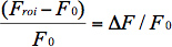
- Present relative changes in fluorescence as a trace with ΔF/F0 for the Y-axis and time for the X-axis.
Results
This protocol provides a non-disruptive approach for direct imaging of free ER calcium. Low-affinity synthetic Ca2+ indicators are released and trapped in the ER lumen with the help of an ER targeted, recombinant esterase enzyme activity. Improved loading of the Ca2+ indicator dyes to the ER lumen enables a direct and fast imaging of ER calcium store dynamics.
Cell types for TED
The feasibility of the method has been shown in the cell lines BHK21, HEK293 34, HeLa 17, SH-SY5Y, cultured astrocytes 8,40 and primary hippocampal and cortical neurons 8,34,41. In our experiments, TED works well when TED constructs are stably expressed, preferentially by self-inactivating lentiviral vectors 37,39 using a relatively weak promoter (e.g. the ubiquitin promoter) 35. Other, stronger promoters are under investigation.
ER-specificity of the TED label
Successful TED loading with Fluo5N offers a clear and bright staining of the ER lumen, which is spared out of the nuclear region 34,41. At resting states, the Fluo5N/Ca2+ complex label represents the localization of calcium when bound by Fluo5N, hence, it represents the regional distribution of free calcium in the ER lumen. In Figure 6, confocal images of Fluo5N/Ca2+-complexes and Tag-RFP-T2 labels of Red-CES2 are shown in HeLa cells, cortical astrocytes and hippocampal neurons. Figure 6C reveals the fluorescent Ca2+ indicator complex in the cell body as well as neurites of hippocampal neurons. This enables examination of Ca2+ signals in rather small processes (see also 34,35).
Some experience is needed to distinguish the typical ER label from a cytosolic label that will be observed when cells are damaged or unhealthy. Cytosolic, endogenous esterases also release Fluo5N, which leads to a very bright staining of the cytosol and the nucleus when calcium is leaking through the plasma membrane. Cytosolic staining of Fluo5N/Ca2+ is also observed when TED-labeled cells are treated with the ionophore ionomycin, in the presence of extracellular calcium (Figure 7).
Direct imaging of calcium release from the ER
One major application of TED is the direct visualization of ER store depletion 17,34. In Figure 8, we show one representative experiment performed with hippocampal neurons, expressing Red-CES2. Neurons with Red-CES2 enrich high amounts of Fluo5N in the perinuclear region (arrows in Figure 8). When the SERCA blocker CPA is applied by perfusion, a rapid depletion of the ER calcium store is observed (Figure 8B). Here we present the raw values (y-axis) that are obtained when neurons are imaged with 12-bit. Imaging conditions are listed in Table 2. Note the enormous change in mean fluorescence density per ROI that is observed when TED is applied to neurons. For other experiments analyzing ER calcium release in neurons using TED, we would like to refer to earlier experiments, which had already been discussed in detail 8,34,35. In brief, TED in neurons in vitro is used to visualize the SERCA-sensitive ER calcium store in great detail by inverted confocal laser scanning microscopy 8,34 and was successfully applied for fast imaging (15 Hz) of mGluR1/5 induced IiCR 34.
Figure 9 shows a typical experiment with mouse cortical astrocytes in vitro, stimulated by 200 μM ATP through the perfusion system at low resolution using a 20x water objective. After lentiviral infection, the cells shown here expressed Red-CES2, which is driven by an ubiquitin promoter. Scanning speed was ~2 Hz and both channels (Fluo5N/Ca2+ and Red-CES2 fusion protein) were simultaneously imaged (in line). At the beginning of the experiment the glial cells showed good infection with the expression constructs and good loading with Fluo5N-AM. The ROIs that were analyzed are highlighted in Figure 9A. One ROI was set to measure the background fluorescence (bg), ROI 1-2 measure the fluorescence of complete cells, ROI 3 covers just the ER of the cell and ROI 4 was drawn around the complete visual field. Shortly after stimulation with ATP the fluorescence of the Fluo5N/Ca2+ complexes abruptly dropped down due to Ca2+ release from the ER. Finally, the ER is partially refilled with calcium again. Simultaneously, the fluorescence of the RFP continuously decreases as a consequence of slight bleaching (Figure 9B, lower panel). Traces representing changes in fluorescence intensity (Figure 9C) point to an important disadvantage of TED. In many (not all) experiments high amounts of Fluo5N-complexes are lost during stimulation. As a consequence, the fluorescence values do not come back to the initial fluorescence intensity level.
Figure 10 shows a CES2-infected BHK21 cell at high resolution, labeled by Fluo5N/Ca2+ and stimulated with ATP. BHK21 cells served as an early model cell system for ER calcium analysis 31. Note that ER calcium release and store-refilling is visualized in fine structures of the ER tubules. The structures had been imaged at slow speed (~0.2 Hz), with 512 x 512 pixel, Airy disc 1 setting for the confocal pinhole, and with a 63x oil objective.
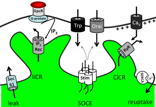
Figure 1. Overview of ER calcium signaling. ER calcium release is caused by "leak" channels such as the ER intramembrane pore complex Sec61. G-protein coupled receptors (GpcR) stimulate IP3 production, which then causes IP3-induced calcium release (IiCR). ER calcium release is sensed by the STIM complexes and induces store-operated calcium entry (SOCE) by ion channels of the Trp family and/or Orai calcium channels. Voltage-gated calcium channels (CaV) mediate fast calcium-induced calcium release (CiCR) by ryanodine receptors (RyR) either by direct protein interaction (skeletal muscle) or physiological interaction (heart muscle cells, neurons). The loss of ER calcium is dynamically rescued by the action of the SERCA pump (sarcoplasmic-endoplasmic reticulum calcium ATPase).

Figure 2. Principle of targeted-esterase induced dye loading (TED). Targeted overexpression of a carboxylesterase provides a high esterase activity (CES2) in the ER. The esterase converts the acetoxymethylester dye Fluo5N-AM to a calcium-sensitive, fluorescent dye that remains trapped in the ER. Fluo5N has a low-affinity to calcium ions. Therefore, under resting conditions, fluorescent Fluo5N/Ca2+ complexes are preferentially formed in the ER, where the calcium concentration is approximately 1,000-fold higher than in the cytosol.
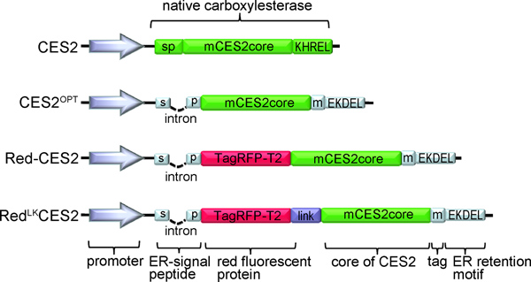
Figure 3. Representative TED vector constructs. CES2: Native version of mouse CES2. CES2OPT 43: The ER signal peptide was exchanged and now includes an intron, while the ER retention motif was changed to the classical KDEL-ER retention and retrieval motif of soluble ER proteins. A myc tag provides an epitope for protein detection by indirect immunofluorescence labeling and Western blot analysis. Red-CES2 8,43: A red fluorescent protein was added straight behind the aminoterminal signal peptide. RedLKCES2 43: A glycine-serine linker has been introduced to establish a flexible hinge between the RFP and the CES2 element .
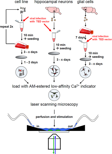
Figure 4. Work flow for direct ER calcium imaging using TED. Cell suspensions of primary cells or cell lines are transduced with a virus containing a TED expression construct. Cells are then seeded on coverslips. When using RFP-CES2 constructs, transduced cells can be identified using the red fluorescence. Target-esterase induced dye loading is performed by incubating the cells in an imaging solution containing an AM-coupled low-affinity Ca2+ indicator, such as Fluo5N-AM or Mag-Fura2-AM. ER calcium imaging is performed with an inverted laser scanning microscope (see protocol) or any other compatible imaging device. During live imaging the cells are under continuous perfusion with an imaging solution such as artificial cerebrospinal fluid (ACSF). Cell stimulation is performed either by perfusion or by local pressure-ejection.
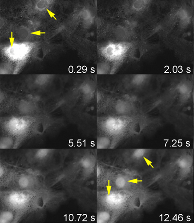
Figure 5. Strong epifluorescence illumination destroys the ER-specific Fluo5N TED label within seconds. Representative images from a video, imaged with an upright imaging microscope. Here, glial cells expressing RFP-CES2 were loaded with Fluo5N-AM. First the red fluorescence of an infected cell was revealed with a CCD camera. Subsequently, the Fluo5N/Ca2+ signal was illuminated with a LED light source. An initial clear ER localization of Fluo5N/Ca2+ complexes (yellow arrows) is rapidly destroyed by strong illumination with a 470 LED light source and a shift in the fluorescence distribution becomes visible in the nuclear area (yellow arrows, 12.46 sec).
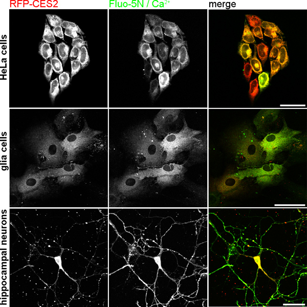
Figure 6. TED loading with Fluo5N-AM in different cell types. Upper panel: HeLa cells with stable RED-CES2 expression. Middle panel: cortical astrocytes after lentiviral transduction with Red-CES2. Lower Panel: hippocampal neurons with RED-CES2 at DIV 8. All cells were cultured on coverslips and stained with Fluo5N-AM as described in the method section. The Fluo5N/Ca2+ label also represent the localization of calcium when bound to Fluo5N. Scale bar 40 μm.
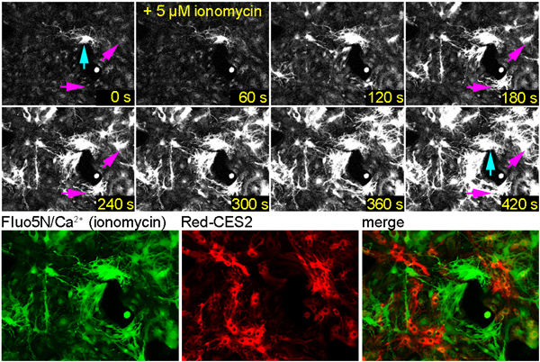
Figure 7. Fluo5N dye in the cytosol becomes visible after ionomycin treatment. Glial cells were infected with Red-CES2, labeled with Fluo5N-AM, and treated with the SERCA-blocker thapsigargin to deplete ER calcium. Ionomycin treatment induced a strong influx of extracellular calcium. (Upper panel) Cells show a drastic increase in Fluo5N/Ca2+-mediated fluorescence. (Lower panel) The average intensity projection image of the Fluo5N/Ca2+-label reveals a typical cytosolic labeling by the fluorescent calcium complex. Blue arrow: A brightly labeled cell indicates that this cell has high amounts of calcium in the cytosol. Presumably, this cell is damaged. Purple arrow: Cells become brightly labeled in the cytosol upon ionomycin treatment.
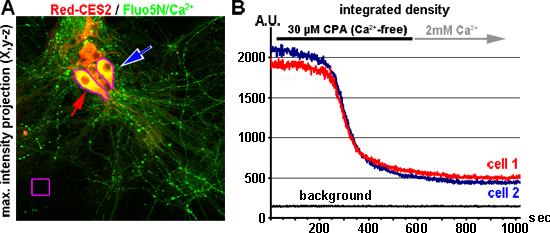
Figure 8. ER calcium store depletion in neurons by blocking the SERCA. (A) Hippocampal neurons (DIV 9) express Red-CES2 (A, red) and are labeled with Fluo5N-AM (A, green). The arrows point to two analyzed cells. The image (maximum intensity projection) is a cropped element of a x,y-z-image that was acquired at the beginning of the experiment. (B) Raw traces representing the ER calcium store depletion after perfusion with 30 μM CPA. Here 1,000 images were taken with 1 Hz and 12-bit. The raw values of the mean fluorescence density per ROI (Y-axis) of the two cells shown in A are plotted over time (red and blue trace). The background values (black trace) remain constant. A.U.= arbitrary units of grey values representing the fluorescence density.
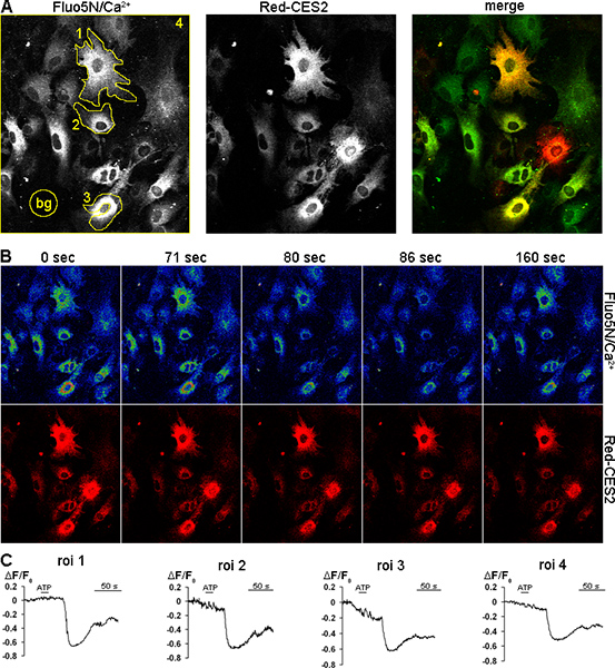
Figure 9. ER calcium release upon ATP stimulation of glial cells. Glial cells were infected with Red-CES2 and loaded with the Ca2+ indicator Fluo5N-AM. Cells were stimulated with 200 μM ATP via perfusion for 10 sec. (A) Glial cells expressing Red-CES2 (middle) are labeled with Fluo5N-AM (left). The ROIs are highlighted. (B) Single pictures extracted from the time-lapse sequence. (Upper panel) The fluorescence intensity is high at 0 sec and 71 sec before the cells react. It abruptly drops (80 sec) and reaches a minimum at 86 sec, before it rises again (160 sec) as calcium is pumped back into the ER. (lower panel) Fluorescence intensity of the RFP decreases slowly and continuously over time due to bleaching. (C) Time traces showing ΔF/F0 values for the ROIs indicated in A. The fluorescence, indicating the calcium concentration, drops down after ATP stimulation and partially recovers. Click here to view larger figure.
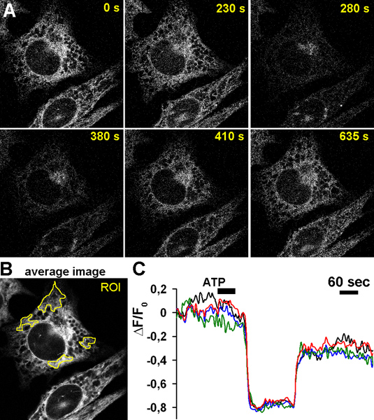
Figure 10. High resolution imaging of ATP-induced calcium release in BHK21 cells. Cells were loaded with Fluo5N-AM and imaged in the presence of extracellular calcium. (A) Image series showing changes in Fluo5N/Ca2+-derived fluorescence during ATP-stimulation. (B) Average intensity projection image indicates the ROIs shown in C. (C) ATP induced calcium release and refilling of the ER calcium store is analyzed in small subregions of the ER. The traces represent changes in fluorescence.
| Excitation laser [nm] | Detection range [nm] |
| TED with Red-CES2 vector constructs | |
| 473 (Fluo5N/Ca2+) | 507-545 |
| 559 (Tag-RFP-T2) | > 570 |
| TED with CES2 only vector constructs | |
| 473 nm (Fluo5N/Ca2+) | > 507 |
Table 1. Settings for the spectral detector.
| Experiment | ER depletion using a Red-CES2 | Stimulation of neurons using a CES2 construct | High spatial resolution imaging, CES2 |
| Objective(N.A) | 20x water (0.7) | 20x water (0.7) | 40x oil/63x oil (≥1,3) |
| 473 nm Laser | |||
| Power | 1% | 1% | |
| HVA | 600-780 | 600-780 | 400-780 |
| GainB | 0-1% | 1-2% | 0% |
| Offset | 0 | 0 | 0 |
| 559 nm Laser | |||
| power | 1% | optionalC | optionalC |
| HVA | 600-780 | optionalC | optionalC |
| GainB | 0-1% | optionalC | optionalC |
| Offset | 0 | optionalC | optionalC |
| Scanning speed | 1-2Hz | Free run | Free run |
| Picture size | 320x320 pixel | 240x240 pixel | 512x512 pixel |
| Scanning type | In line | Bidirectional | Nyquistcriterion (2 pixels/element) |
| Stimulation | 100-200 μM ATP:5-15 sec; 200-500 μM glutamate for 5-15 sec | 100-200 μM Agonist: 5-15 sec | |
| Pinhole | 2-5 airy discs | 2-5 airy discs | 1 airy disc |
Table 2. Examples of microscope settings according to the type of experiment. A : HV = current to the photomultiplier detector, B: gain = amplification of the PMT signal, C : optional: channel is free for use with other red fluorescent dyes (e.g. CMX-Ros for visualizing the mitochondrial potential) or other red fluorescent proteins.
Discussion
The advantages and disadvantages of the TED method have been discussed extensively in recent publications 34,35. Compared to other methods described above, TED circumvents the problem of disrupting and perfusing the cells. Furthermore, two aspects need to be emphasized. The principle of TED for ER calcium imaging requires (1.) the targeted expression of an active carboxylesterase in the ER lumen with the help of TED vector constructs and (2.) the efficient and preferential release of low-affinity synthetic AM-esters of calcium dyes in the ER lumen.
1. TED vector constructs
Figure 3 summarizes the development of TED vector constructs. TED was developed on the basis of CES family proteins (EC 3.1.1.1). These proteins are resident members in the ER lumen. For in vitro studies the recombinant administration of CES proteins works best after stable expression of the protein or after viral infection with moderate expression levels. At present, it is unknown whether other proteins with esterase activity can replace CES proteins for TED imaging. It is not recommended to use transient transfection of TED vectors for dynamic ER calcium analysis because cells are less responsive after the transfection procedure. CES proteins need proper targeting to the ER lumen and this step needs an efficient cleavage of the ER signal peptide. In addition, retention and retrieval of CES proteins in the ER lumen is mediated by their aminoterminal KDEL-like motif. These mechanisms may be saturated when high expression levels are produced by TED vectors after transient transfection. This may causes a false localization of the CES-proteins and supports the formation of protein aggregates.
2. Low-affinity Ca2+ Indicators for TED
The most important drawback of TED is caused by limitations of available indicator dyes for the non-disruptive analysis of ER calcium. ER calcium imaging with TED requires indicator dyes with a high KD (meaning a low affinity) and a low fluorescence in the absence of calcium. Basing on our experience Fluo5N-AM works best, but this indicator dye is not bleach-resistant. The low-affinity Ca2+ indicators Mag-Fura2-AM (KD ~ 25-50 μM) 34 and Mag-Fluo4 (KD ~ 20-25 μM) were also tested. Both dyes are well loaded into ER structures by TED, but the risk of producing "mixed signals" upon stimulation of ER release is high. A "mixed signal" represents first a fast increase of fluorescence in the cytosol followed by decrease of fluorescence in the ER. To overcome this limitation, disruptive approaches for ER calcium imaging may help 32,35. Mag-Fluo4 (KD ~ 20-25 μM) shows a strong TED-mediated label of the Golgi cisternae, which is less pronounced when Fluo5N-AM is used.
Applications and Perspectives
Here we focus on inverse laser scanning confocal analysis of ER calcium dynamic with TED. TED measurements can also be adapted to any standard confocal system or wide-field system with the appropriate excitation source (laser, LED, metal halid lamps, monochromator), filters and fluorescence detection system 6.
TED is especially useful in those cells that do not express sufficient endogenous CES activity in the ER. We observed that e.g. BHK21 cells provide enough endogenous esterase activity in the ER to release low affinity indicators. In our hands, this is not the case with many other cell lines (HEK293, SH-SY5Y, HeLa, PC12), primary glia, and primary neurons. Here, the TED method enables a successful non-disruptive dye loading to the ER.
Future TED vectors may extent its application from the ER lumen to other subcellular compartments or cellular microdomains. The principle of the TED method is independent of the indicator dye, and can therefore be used with the AM-ester of any dye, for instance for the imaging of intracellular pH dynamics. Recently, the laboratory of Luke D. Lavis described that the recombinant porcine liver esterase (PLE) CES1 forms a selective esterase-ester pair with cyclopropylester dyes 42. Cyclopropylester agents were found to be resistant to hydrolysis by endogenous esterases and the selective unmasking by the recombinant CES activity enabled cell specific molecule targeting 42. It will be interesting to investigate whether calcium indicators basing on that new technique will improve the subcellular targeting specificity of synthetic indicators.
TED works best in cell lines when TED proteins are stably expressed. The establishment of a collection with stable TED cell lines would be beneficial.
Transgenic TED mouse models are also a major aim of our work and this will enable TED in specific tissue preparations from specific neuronal circuits, skeletal muscle, heart, or preparations of the vascular system. This mouse model will help to transfer the analysis of ER calcium dynamics from the cellular level to more physiological tissue context.
Disclosures
The authors declare that they have no competing financial interests.
Acknowledgements
This work has been supported by grants of the Deutsche Forschungsgemeinschaft (DFG) BL567/3-1 and the Friedrich-Baur-Stiftung. We would like to thank Roger Y. Tsien, Howard Hughes Medical Institute Laboratories at the University of California, San Diego for providing us with Tag-RFP-T2. We thankfully acknowledge David Baltimore, California Institute of Technology, Pasadena, and Didier Trono, University of Geneva, Geneva, for providing us the lentiviral plasmids FUGW, and psPAX2/pMD2.G.
Materials
| Name | Company | Catalog Number | Comments |
|---|---|---|---|
| (S)-3,5-DHPG (Dihydroxyphenylglycine) | Tocris | 0805 | |
| 5';-ATP-Na2, ATP disodium salt hydrate | Sigma | A26209-1G | |
| B-27 supplement,50x | Invitrogen | 17504-044 | |
| Carbamoylcholine chloride (Charbachol) | Sigma | C4382-1g | |
| Cyclopiazonic acid (CPA) | Ascent scientific | Asc-300 | |
| Dimethylsulfoxide (DMSO) | Sigma | D2650 | |
| DMEM with Glutamax | Invitrogen-Gibco | 31966-047 | |
| Dulbecco's PBS without Ca/Mg 1x | PAA | H15-002 | |
| Fetal calf serum | Invitrogen-Gibco | 10270-106 | |
| Fluo-5N-AM, 10 x 50 μg | Invitrogen | F14204 | |
| Glutamate | Ascent scientific | Asc-049 | |
| Glutamax | Invitrogen | 35050-038 | |
| Ham's F12 nutrients mixture | Invitrogen-Gibco | 21765-029 | |
| Hank's BSS(1x) without Ca,without Mg, with Phenol Red, HBSS | PAA Laboratories | H15-010 | |
| Horse serum | SHD3250YK | Linearis | |
| Ionomycin Ca2+ salt | Ascent scientific | Asc-116 | |
| murine EGF | PreproTech | 315-09 | |
| N2 supplement 100x | Invitrogen | 17502-048 | |
| Neurobasal medium | Invitrogen-Gibco | 21103-049 | |
| Pluronic F127, low UV absorbance,2g | Invitrogen | P6867 | |
| Poly-DL-ornithine hydrobromide PORN | Sigma | P8638 | |
| Poly-D-lysine hydrobromide | Sigma | P7280 | |
| Poly-L-Lysin | Sigma | P2636 | |
| Thapsigargin | Calbiochem | 586005-1mg | |
| TryLE Express | Invitrogen | 12605-028 | |
| Trypsin | Worthington | LS-003707 | |
| Trypsininhibitor from Glycine MAX (soybean) | Sigma | T6522 | |
| Materials | |||
| Confocal system: inverted laser scanning microscope: FV1000 with IX81 | Olympus | user-specific configuration | |
| Confocal system: laser combiner FV10 and diode lasers (405, 473, 559, 635) | Olympus | user-specific configuration | |
| Confocal system: scan head FV10-SPD with spectraldetector | Olympus | user-specific configuration | |
| Heater controller TC-344B | Warner Instruments | 64-0101 | to control in line solution heater |
| NIH ImageJ software | WS Rasband, ImageJ, US National Institutes of Health, http://rsb.info.nih.gov/ij/, 1997--2006 | ||
| Objective: UAPON20XW340 NA 0,7 WD 0,35 | Olympus | N2709100 | |
| Objective: UPLFLN40XO | Olympus | N1478700 | |
| Objective: UPLSAPO60XO/1.35, WD=0.15 | Olympus | N1480700 | |
| Perfusion chamber, inverse | custom-made | ||
| Perfusion chamber, RC-49FS | Warner Instruments | W4 64-1709 | |
| Perfusion tube: PT-49 | Warner Instruments | 64-1730 | for perfusion |
| Peristaltic pump MiniPlus 3 (4 channels) | Gilson | n.a. | perfusion pump |
| Single inline solution heater SH-27B | Warner Instruments | 64-0102 | controlled by heater controller |
| Suction tubes: ST3R | Warner Instruments | 64-1407 | for perfusion |
| Heating insert: Tempocontrol 37-2 digital 2-channel | Pecon | n.a. |
References
- Berridge, M. J., Bootman, M. D., Roderick, H. L. Calcium signalling: dynamics, homeostasis and remodelling. Nature reviews. Molecular Cell Biology. 4, 517-529 (2003).
- Berridge, M. J., Lipp, P., Bootman, M. D. The versatility and universality of calcium signalling. Nature reviews. Molecular Cell Biology. 1, 11-21 (2000).
- Agulhon, C., et al. What is the role of astrocyte calcium in neurophysiology. Neuron. 59, 932-946 (2008).
- Augustine, G. J., Santamaria, F., Tanaka, K. Local calcium signaling in neurons. Neuron. 40, 331-346 (2003).
- Berridge, M. J. Neuronal calcium signaling. Neuron. 21, 13-26 (1998).
- Grienberger, C., Konnerth, A. Imaging calcium in neurons. Neuron. 73, 862-885 (2012).
- Neher, E., Sakaba, T. Multiple roles of calcium ions in the regulation of neurotransmitter release. Neuron. 59, 861-872 (2008).
- Jaepel, J., Blum, R. Capturing ER calcium dynamics. European Journal of Cell Biology. 90, 613-619 (2011).
- Verkhratsky, A. Physiology and pathophysiology of the calcium store in the endoplasmic reticulum of neurons. Physiological Reviews. 85, 201-279 (2005).
- Burdakov, D., Petersen, O. H., Verkhratsky, A. Intraluminal calcium as a primary regulator of endoplasmic reticulum function. Cell Calcium. 38, 303-310 (2005).
- Streb, H., Irvine, R. F., Berridge, M. J., Schulz, I. Release of Ca2+ from a nonmitochondrial intracellular store in pancreatic acinar cells by inositol-1,4,5-trisphosphate. Nature. 306, 67-69 (1983).
- Choi, J. H., Ryu, S. H., Suh, P. G. On/off-regulation of phospholipase C-gamma 1-mediated signal transduction. Advances in Enzyme Regulation. 47, 104-116 (2007).
- Clapham, D. E. TRP channels as cellular sensors. Nature. 426, 517-524 (2003).
- Cahalan, M. D. STIMulating store-operated Ca(2+) entry. Nature Cell Biology. 11, 669-677 (2009).
- Soboloff, J., Madesh, M., Gill, D. L. Sensing cellular stress through STIM proteins. Nature Chemical Biology. 7, 488-492 (2011).
- Erdmann, F., et al. Interaction of calmodulin with Sec61alpha limits Ca2+ leakage from the endoplasmic reticulum. The EMBO Journal. 30, 17-31 (2011).
- Schäuble, N., et al. BiP-mediated closing of the Sec61 channel limits Ca(2+) leakage from the ER. The EMBO Journal. , (2012).
- Park, M. K., Choi, Y. M., Kang, Y. K., Petersen, O. H. The endoplasmic reticulum as an integrator of multiple dendritic events. The Neuroscientist : a review journal bringing neurobiology, neurology and psychiatry. 14, 68-77 (2008).
- Cooney, J. R., Hurlburt, J. L., Selig, D. K., Harris, K. M., Fiala, J. C. Endosomal compartments serve multiple hippocampal dendritic spines from a widespread rather than a local store of recycling membrane. The Journal of Neuroscience : the official journal of the Society for Neuroscience. 22, 2215-2224 (2002).
- Holbro, N., Grunditz, A., Oertner, T. G. Differential distribution of endoplasmic reticulum controls metabotropic signaling and plasticity at hippocampal synapses. Proceedings of the National Academy of Sciences of the United States of America. 106, 15055-15060 (2009).
- Terasaki, M., Slater, N. T., Fein, A., Schmidek, A., Reese, T. S. Continuous network of endoplasmic reticulum in cerebellar Purkinje neurons. Proceedings of the National Academy of Sciences of the United States of America. 91, 7510-7514 (1994).
- Barreto-Chang, O. L., Dolmetsch, R. E. Calcium imaging of cortical neurons using Fura-2 AM. J. Vis. Exp. (23), e1067(2009).
- Lang, S., Schäuble, N., Cavalie, A., Zimmermann, R. Live cell calcium imaging combined with siRNA mediated gene silencing identifies Ca(2)(+) leak channels in the ER membrane and their regulatory mechanisms. J. Vis. Exp. (53), e2730(2011).
- Rudolf, R., Mongillo, M., Rizzuto, R., Pozzan, T. Looking forward to seeing calcium. Nature reviews. Molecular Cell Biology. 4, 579-586 (2003).
- Mank, M., Griesbeck, O. Genetically encoded calcium indicators. Chemical Reviews. 108, 1550-1564 (2008).
- Miyawaki, A., et al. Fluorescent indicators for Ca2+ based on green fluorescent proteins and calmodulin. Nature. 388, 882-887 (1997).
- Montero, M., et al. Monitoring dynamic changes in free Ca2+ concentration in the endoplasmic reticulum of intact cells. The EMBO Journal. 14, 5467-5475 (1995).
- Griesbeck, O., Baird, G. S., Campbell, R. E., Zacharias, D. A., Tsien, R. Y. Reducing the environmental sensitivity of yellow fluorescent protein. Mechanism and applications. The Journal of Biological Chemistry. 276, 29188-29194 (2001).
- Ishii, K., Hirose, K., Iino, M. Ca2+ shuttling between endoplasmic reticulum and mitochondria underlying Ca2+ oscillations. EMBO Reports. 7, 390-396 (2006).
- Palmer, A. E., Jin, C., Reed, J. C., Tsien, R. Y. Bcl-2-mediated alterations in endoplasmic reticulum Ca2+ analyzed with an improved genetically encoded fluorescent sensor. Proceedings of the National Academy of Sciences of the United States of America. 101, 17404-17409 (2004).
- Hofer, A. M., Machen, T. E. Technique for in situ measurement of calcium in intracellular inositol 1,4,5-trisphosphate-sensitive stores using the fluorescent indicator mag-fura-2. Proceedings of the National Academy of Sciences of the United States of America. 90, 2598-2602 (1993).
- Solovyova, N., Verkhratsky, A. Monitoring of free calcium in the neuronal endoplasmic reticulum: an overview of modern approaches. Journal of Neuroscience Methods. 122, 1-12 (2002).
- Solovyova, N., Veselovsky, N., Toescu, E. C., Verkhratsky, A. Ca(2+) dynamics in the lumen of the endoplasmic reticulum in sensory neurons: direct visualization of Ca(2+)-induced Ca(2+) release triggered by physiological Ca(2+) entry. The EMBO Journal. 21, 622-630 (2002).
- Rehberg, M., Lepier, A., Solchenberger, B., Osten, P., Blum, R. A new non-disruptive strategy to target calcium indicator dyes to the endoplasmic reticulum. Cell Calcium. 44, 386-399 (2008).
- Blum, R., Verkhratsky, A., Petersen, O. H. Calcium imaging of intracellular organelles: endoplasmic reticulum. 43, Humana Press. (2010).
- Shaner, N. C., et al. Improving the photostability of bright monomeric orange and red fluorescent proteins. Nature Methods. 5, 545-551 (2008).
- Lois, C., Hong, E. J., Pease, S., Brown, E. J., Baltimore, D. Germline transmission and tissue-specific expression of transgenes delivered by lentiviral vectors. Science. 295, 868-872 (2002).
- Zufferey, R., et al. Self-inactivating lentivirus vector for safe and efficient in vivo gene delivery. Journal of Virology. 72, 9873-9880 (1998).
- Zufferey, R., Nagy, D., Mandel, R. J., Naldini, L., Trono, D. Multiply attenuated lentiviral vector achieves efficient gene delivery in vivo. Nature Biotechnology. 15, 871-875 (1997).
- Li, D., Herault, K., Oheim, M., Ropert, N. FM dyes enter via a store-operated calcium channel and modify calcium signaling of cultured astrocytes. Proceedings of the National Academy of Sciences of the United States of America. 106, 21960-21965 (2009).
- Blum, R., Petersen, O. H., Verkhratsky, A. Calcium measurement methods. Verkhratsky, A., Petersen, O. H. Vol. Neuromethods 43 (Springer protocols), Humana Press. 147-167 (2010).
- Tian, L., et al. Selective esterase-ester pair for targeting small molecules with cellular specificity. Proceedings of the National Academy of Sciences of the United States of America. 109, 4756-4761 (2012).
- Samtleben, S., Blum, R. Improved vectors for direct ER calcium imaging with targeted-estersase induced dye loading. , In preparation (2012).
Reprints and Permissions
