We use an isothermal adsorption apparatus, the gravimetric sorption analyzer, to test the adsorption capacity of different particle sizes of shale, in order to find out the relationship between particle size and the adsorption capacity of shale.
A subscription to JoVE is required to view this content. Sign in or start your free trial.
Method Article
Experimental Study of the Relationship Between Particle Size and Methane Sorption Capacity in Shale
In This Article
Summary
Abstract
The amount of adsorbed shale gas is a key parameter used in shale gas resource evaluation and target area selection, and it is also an important standard for evaluating the mining value of shale gas. Currently, studies on the correlation between particle size and methane adsorption are controversial. In this study, an isothermal adsorption apparatus, the gravimetric sorption analyzer, is used to test the adsorption capacity of different particle sizes in shale to determine the relationship between the particle size and the adsorption capacity of shale. Thegravimetric method requires fewer parameters and produces better results in terms of accuracy and consistency than methods like the volumetric method. Gravimetric measurements are performed in four steps: a blank measurement, preprocessing, a buoyancy measurement, and adsorption and desorption measurements. Gravimetric measurement is presently considered to be a more scientific and accurate method of measuring the amount of adsorption; however, it is time-consuming and requires a strict measuring technique. A Magnetic Suspension Balance (MSB) is the key to verify the accuracy and consistency of this method. Our results show that adsorption capacity and particle size are correlated, but not a linear correlation, and the adsorptions in particles sieved into 40 - 60 and 60 - 80 meshes tend to be larger. We propose that the maximum adsorption corresponding to the particle size is approximately 250 µm (60 mesh) in the shale gas fracturing.
Introduction
Shale is a clay rock with a thin sheet of bedding structure, which serves as both a shale gas source rock and a reservoir. Shale has a strong anisotropy consisting of nano- and micron-scale pores, and graptolite fossils are commonly recognized1,2,3.
Shale gas is commercially exploited in the Yangtze Plate, Southern China. As an unconventional gas system that serves as both a source rock and a reservoir for methane, shale gas is derived from the organic matter within the shale through biogenic and/or thermogenic processes4,5. Natural gas stores in reservoirs are in one of three forms: free gas in pores and fractures, adsorbed gas on the surface of organic matter or inorganic minerals, and dissolved gas in bitumen and water6,7. Previous studies suggest that adsorbed gas accounts for 20 - 85% of the total gas in shale formations6. Therefore, research on the adsorption capacity of shale and its controlling factors are significant to the exploration and development of shale gas resource.
The methane adsorption ability of shale has been widely recognized as significantly varying with temperature, pressure, humidity, maturity, mineral composition, organic matter, and specific surface area1,4,5,6,7; and previous studies have confirmed a larger and clearer correlation between external factors like temperature, pressure, and humidity and methane adsorption.
However, studies on the correlation between intrinsic factors like particle size and methane adsorption are controversial. Kang and Ji suggest that the methane adsorption capacity of the same shale samples increases with a decrease in particle size8,14, whereas Rupple and Zhang believe the relevance between the particle size and adsorption is limited based on the isothermal adsorption curves9,10,11. In addition, without standards for a shale gas adsorption evaluation protocol, laboratories in China typically apply the coal adsorption evaluation protocols for evaluating shale gas adsorption. To clarify the relationship between particle size and adsorption,as well as investigate a prospective exploration zone, we obtained shale samples from the thick marine shale deposits of the Wuling Sag in the Upper Yangtze Plate. A gravimetric sorption analyzer was applied to conduct the isothermal adsorption experimentand obtain the relationship between the particle size and adsorption.
The volumetric and gravimetric methods are the main methods used to test the isothermal adsorption of shale. Volume is the key parameter of the volumetric method, which is easily affected by temperature and pressure12,13,14. Because of uncertainty in the error analysis, the cumulative propagation in direct measurements using the volumetric method for calculating adsorption amounts leads to a large error in the measurement results, which causes an abnormal adsorption isotherm14,15. Compared with the volumetric method, the gravimetric method requires fewer parameters and results in smaller errors: because the mass is conserved, the weight and mass of the gravimetric method are not affected by the temperature and pressure12. It is considered a more scientific and accurate method for measuring theadsorption amount of adsorption at present.
A gravimetric sorption analyzer is used in this experiment, which has a maximum testing pressure of 70 MPa (700 bar) and temperature of 150 °C. The temperature and pressure generated by older apparatus are too low toaccurately simulate the temperature and pressure of the deep underground formation. The key to using a sorption analysis apparatus is reaching the magnetic suspension balance for accurately weighing the sample material, with an accuracy of 10 µg. The apparatus adopts a circulating oil bath heating mode and the temperature range can be controlled for a long time to within 0.2 °C. The accuracy of an old apparatus is low, and thus the error would be larger than that obtained with newer instruments. The experimental operations are performed with the software provided by the apparatus.The operating system will be updated regularly to ensure the analysis is close to the actual underground conditions12.
A magnetic suspension balance (MSB) is used in the gravimetric method to test the methane isothermal adsorption of shale without direct contact between the sample and the equipment, in normal temperature and pressure. The sample is placed in the measuring pool, in which the weight of the sample can be transmitted to the balance through a non-contact suspension coupling mechanism12,13. Under the balance, there is a suspended magnet, controlled by a specially designed controller that allows the free suspension of the permanent magnet below. The permanent magnet connects the position sensor and the sample container with the coupling frame. The function of the coupling frame is to couple or decouple the sample container to the permanent magnet suspension rod14,15,16.
Our measured samples are black organic-rich shales deposited in marine facies of the Long Maxi formation, Lower Silurian in the Daozhen, Guizhou province. The research area is in the Wuling Sag, upper Yangtze plate, which is bordered by the Sichuan Basin to the northwest and Xuefeng Mountain tectonic zone to the southwest17. The Wuling Sag is a structural transfer and transition zone between the Sichuan Basin and Xuefeng Mountain tectonic zone, which received shallow-deep sea shelf deposits, and marine black shale was widely developed during the early Silurian; the sag was then strongly superimposed by tectonic events like the Indo-China Movement, Yanshan Movement, and Himalayan Movement, which formed multistage folds, faults, and unconformities18. The marine black shale in the Wuling Sag has been significantly influenced by the complex geological conditions, which formed shale gas reserves. As a structural transfer zone, the sag is the sweet spot for shale gas exploration, which is characterized by a weaker deformation, better shale gas generation and preservation conditions, and a better natural fracture matching of the traps19.
High-pressure sorption measurements are conducted based on a standardized procedure with the guidance of the isothermal adsorption apparatus protocol, which has been comprehensively elaborated on in several publications10,11,12,13,14,15,16. The isothermal adsorption experiments were completed in the Key Laboratory of Shale Oil and Gas Investigation and Evaluation of the Chinese Academy of Geosciences. A gravimetric measurement carried out with a magnetic suspension balance (MSB) is performed in four steps: a blank measurement, preprocessing, a buoyancy measurement, and an adsorption and desorption measurement (Figure 1, Figure 2).
Access restricted. Please log in or start a trial to view this content.
Protocol
1. Sample Preparation
- Sample characterization
- Measure the total organic carbon (TOC) using a TOC apparatus (see Table of Materials) at a temperature of 20 °C and a relative humidity of 65% (per standard GB/T 19145-2003).
- Perform a vitrinite reflectance measurement on polished sections of the shale using a photometer microscope (see Table of Materials).
- Sample cleaning and crushing
NOTE: To avoid the influence of various internal and external factors as well as the inhomogeneity of shale as much as possible, select a large shale rock sample from the original horizontal bedding for this experiment.- Select a large shale rock sample (about 20 cm long, 15 cm wide, and 2 cm high) from the original horizontal bedding.
- Clean the sample and crushing vessel with absorbent cotton, tweezers, and acetaldehyde.
- Smash the large original horizontal shale beddingsample into small pieces with a hammer, so that it can be placed into the residual gas tight grinder. The suitable crushing time (approximately 3 min) can be found through preliminary experiments.
- Then, sieve the sample into 20 - 40, 40 - 60, 60 - 80, 80 - 100, and 100 - 120 subsamples by first sieving particles through a 100 - 120 mesh, then a 80 - 100 mesh, 60 - 80 mesh, 40 - 60 mesh, and finally the 20 - 40 mesh.
- Discard any non-conforming shale particles. There will be a few discarded samples (approximately 5 g) when the crushing time is 3 min.
- Label each sample as 20-40-1, 40-60-1, 60-80-1, 80-100-1, and 100-120-1 (this is G1 in the Representative Results).
- Repeat the above-mentioned operation with another sample (about 20 cm long, 15 cm wide, and 2 cm high; use a different shale with a different composition or TOC) and create a set of repeat experiments for contrast. Label each sample as 20-40-2, 40-60-2, 60-80-2, 80-100-2, and 100-120-2 (G2 in the Representative Results).
2. Experimental Methods
- Laboratory set-up
- Place the instruments in a quiet, vibration-free area of a clean laboratory with no electromagnetic interference.The temperature of the laboratory should be 10 - 40 °C.
Note: The experiment will be conducted at room temperature for extended periods of time (multiple days). - Use alternating current at 230 V (±10%) and 50 Hz. Ensure every root power supply line has a current greater than 10 A and is safely handled with a ground lead. If the power grid is poor, an additional power supply should be used.
- Use gas cylinders with high purity gas (not less than 99.999%). Fix all cylinders firmly.
- If dangerous gas is used in the experiment, ensure that the laboratory has ventilation and exhaust facilities, along with a dangerous gas alarm device. Regularly use soap bubbles to detect any leaks from the pipe connections12.
- Avoid direct sunlight.
- Place the instruments in a quiet, vibration-free area of a clean laboratory with no electromagnetic interference.The temperature of the laboratory should be 10 - 40 °C.
- Start the instrument
- Power on the computer and start the main program.
- Open the cylinder and adjust it to the appropriate output pressure (adjust the outgassing pressure to 5 - 6 bar and the gas cylinder pressure to approximately 70 bar).
- Turn the instrument on. When the coupling controller has been powered on, the knob needs to remain in the OFF position. Open the oil bath and vacuum pump power.
- Blank measurement
- Disassemble the sample pool, place the empty clean sample bucket inside, and install the metal guide sleeve. Check the ZP/MP coupling and adjust it to the appropriate state.
- Control the balance on the coupling controller and switch it to all positions in ZP/MP1/MP2. Observe the changes in the balance reading and confirm the reading is normal and stable. If the reading is incorrect or unstable, it is necessary to adjust the levels on all 4 feet of the flat head, based on the situation, or the high and low position of the support screw.
- Load the sample pool, temperature control oil bath jacket, and heat insulation cover.
- Move the coupling controller knob to the ZP position.
- Set it to the blank measurement program in the software.
- Click to configure the measurement, name a title, select gas 2 and other fluid, and select fluid bath.
- Set the sample temperature to 50 °C, the maximum pressure to 70 bar, the pressure step to 7, the pressure ramp to 2 bar/min, and the fluid therm to 50 °C.
NOTE: For the blank test, use N2 (recommended) or He at the appropriate pressure (0 - 70 bar). Weigh the empty bucket. When the temperature is consistent with the experimental temperature of adsorption, the boot program runs, which usually takes 7 - 8 h. Finally, the quality and volume of the empty bucket can be obtained manually when it is finished (see step 2.8.1).
Caution: 6 sets of bolts on the sample pool flange are dismantled using the internal six-angle wrench and fixed wrench of the instrument.Notice that when the last group of bolts is removed, the sample pool needs to be held to avoid falling.
- Instrument balancing (if necessary)
NOTE: The instrument's operating motion must be a soft, uniform force.- Do not strongly shake the balance support (otherwise, it may upset the balance) or move the position of the frame. When using a wrench, be careful not to knock the sensor traverse tube near the flange out of position.
- When the balance is confirmed, move the ZP to the OFF position.
- Check whether the O ring on the flange of the sample pool is installed. Replace the O ring if there is serious damage or deformation.
- Set up the sample pool vertically, so that the upper and lower flanges are connected, which will maintain the overall vertical state.
- Finally, install 6 groups of bolts.
- Use a wrench to fasten the bolts, using a symmetrical fastening method to ensure that the connection of the flange face is tight and not skewed. The fastening degree of the 6 groups of bolts should be as consistent as possible13.
- Payattention to the spiral cap under the 6 groups of bolts to keep each edge out of the flange, to avoid difficulty when installing the rear oil bath jacket.
- If using electric heating, install insulation terracotta and fix it with a hoop ring without an outside insulation cotton package.
- If using oil bath heating, install the oil bath jacket from the bottom up to the sample pool, until the top and the upper flange are flat. Install three screws at the bottom to fix the oil bath jacket in place.
- Check whether the ZP/MP1/MP2 position and the balance reading are normal, then move the coupling controller knob to the ZP position.
- Preprocessing measurement
- Disassemble the sample pool and place the sample into the sample barrel. Check the ZP/MP coupling and adjust them to the appropriate state.
- Load the sample pool and electric heat insulation cover.
- Move the coupling controller knob to the ZP position.
- The boot program will run automatically. Set the pretreatment program in the software. Click to configure the measurement, name a title, select the vacuum, select the electrical heater, set the sample temperature at 150 °C and the coupling temperature 20 °C, and set the duration at 600 min. This step usually takes 10 h.
- Buoyancy measurement
- Dismantle the electric heating sheath and install the temperature control oil bath jacket and thermal insulation cover, which isadhesive.
- Start the buoyancy measurement program in the software, set the oil bath heating temperature at 50 °C, and heat for approximately 4 h. 7 pressure points will be divided under the maximum pressure of 70 bar. The boot program will run automatically.
NOTE: The buoyancy measurement is the same as the blank measurement.
Caution: Pull out the electric heat power supply joint before removing the temperature sensor joint at the bottom of the sample pool. After loading the sample, remember to check if the temperature sensor is inserted.
- Adsorption measurement
- Set the sorption measurement program in the software. Start the program and it will run automatically.
- If the desorption process is needed, set this up in the sorption measurement program, keep the fluid therm temperature at 50 °C, and set 19 pressure points (e.g., 0, 10, 20, 40, 60, 80, 100, 150, 200, 250, 200, 150, 100, 80, 60, 40, 20, 10, and 0 bar). Then start the program, which will run automatically.
- Set the pressure manually, using a pressurized pump, when the gas pressure cannot reach the set value automatically.
CAUTION: After the end of the experiment, the instrument will automatically exhaust and maintain the vacuum state for a period of time. The program will end automatically, and all the valves will be closed.
- Calculation
- The system can be selected to automatically correct the experimental results by using the following principles. The relationship between the weight reading, tray reading, sample buoyancy, and sorption buoyancy is as follows10,11,12,13:
mA = Δm - mSC - mS + (VSC + VS + VA) X p
mA: mass of adsorption gas; Δm: mass of balance reading; mSC: mass of sample tray (obtained by Blank Measurement); mS: mass of sample (obtained by Buoyancy Measurement); VSC: volume of sample tray (obtained by Blank Measurement); VS: volume of sample(obtained by Buoyancy Measurement); VA: volume of sample adsorption gas (obtained by Adsorption Measurement); ρ(p,T,y): density calculated from the Equation of State or determined through measurement.
- The system can be selected to automatically correct the experimental results by using the following principles. The relationship between the weight reading, tray reading, sample buoyancy, and sorption buoyancy is as follows10,11,12,13:
- Completion
- Exit the program and close the computer. Close the experimental gas cylinder.
- If only a short period of idling occurs, not more than 3 days, stop the power to the instrument, which is not needed to maintain the power state of each system. We suggest that the coupling controller knob is moved to the OFF position.
- If the instrument needs to be stopped for a long time, the power of each system can be turned off. Before the coupling controller power is turned off, the knob first needs to be moved to the OFF position. Confirm that the OFF lamp lights are on and the other lights are out, and then close the controller power.
Access restricted. Please log in or start a trial to view this content.
Results
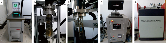
Figure 1: Experimental set-up for gravimetric gas adsorption at high temperatures and pressures. This figure shows the set-up for the isothermal adsorption experiment: (a) the oil bath heating device for the...
Access restricted. Please log in or start a trial to view this content.
Discussion
The materials used in this experiment are shown in the Table of Materials. Before the sample pool is removed, it must be confirmed that the temperature and pressure in the sample pool are at normal pressure and normal temperature; otherwise, there is a danger of injury. If the temperature is too high, wait for the temperature to drop and then removethe sample pool. If the pressure is too high or too low, manually set the air pressure on the software and use an inert gas13,
Access restricted. Please log in or start a trial to view this content.
Disclosures
The authors have nothing to disclose.
Acknowledgements
A lot of assistance was provided by Engineer Gang Chen and Tao Zhang. This work was financially supported by the Major State Research Development Program of China (Grant No.2016YFC0600202) and the China Geological Survey (CGS, Grant No. DD20160183). We thank anonymous reviewers for their constructive comments that greatly improved this paper.
Access restricted. Please log in or start a trial to view this content.
Materials
| Name | Company | Catalog Number | Comments |
|---|---|---|---|
| XRF D8 DISCOVER X-Ray diffractometer | Brook,Germany | 204458 | For mineralogy X-ray diffraction |
| EBSD three element integration system with spectrum | EDAX,USA | Trident XM4 | For nanoscale imaging (SEM) |
| Mercury injection capillary pressure (MICP) | USA micromeritics Instrument company | AutoPore IV 9520 | For the immersion method to measure macropores(Porosity) |
| Nitrogen gas adsorption at low temperature | USA micromeritics Instrument company | ASAP2460/2020 | For the low pressure nitrogen gas adsorption to measure mesopores and micropores(BET) |
| Finnigan MAT-252 mass spectrometer | ThermoFinnigan,USA | TRQ/Y2008-004 | For C isotope |
| LECO CS-230 analyzer | Research Institute of Petroleum Exploration and Development | 617-100-800 | TOC apparatus |
| 3Y-Leica MPV-SP photometer microphotometric system | Leica,Germany | M090063016 | Ro apparatus |
| Magnetic Suspension Balance Isothermal adsorption analyzer | Rubotherm,Germany | 2015-1974CHN | For methane adsorption tests |
| Sieve(20/40/60/80/100/120mesh) | Sinopharm Chemical Reagent Beijing Co.Ltd | 200*50GB6003.102012 | Used to screen samples |
| Absorbent cotton, hammer, tweezers and acetaldehyde | Sinopharm Chemical Reagent Beijing Co.Ltd | standard | Used to clean materials |
| Residual gas tight grinder | Nantong Huaxing Petroleum Instrument Co., Ltd | TY2013000237 | Sample smasher |
References
- Strapoc, D., Mastalerz, M., Schimmelmann, A., Drobniak, A. Geochemical constraints on the origin and volume of gas in the New Albany Shale (Devonian-Mississippian), eastern Illinois Basin. AAPG Bulletin. 94, 1713-1740 (2010).
- Loucks, R. G., Ruppel, S. C. Mississippian Barnett Shale: Lithofacies and depositional setting of a deep-water shale-gas succession in the Fort Worth Basin, Texas. AAPG Bulletin. 91, 579-601 (2007).
- Curtis, J. B. Fractured shale-gas systems. AAPG Bulletin. 86, 1921-1938 (2002).
- Montgomery, S. L., Jarvie, D. M., Bowker, K. A., Pallastro, R. M. Mississippian Barnett Shale, Fort Worth basin, north-central Texas: Gas-shale play with multitrillion cubic foot potential. AAPG Bulletin. 89, 155-175 (2005).
- Jia, C. Z., Zheng, M., Zhang, Y. F. Unconventional hydrocarbon resources in China and the prospect of explora exploration and development. Petroleum Exploration and Development. 39 (2), 129-136 (2012).
- Hou, Y. G., et al. Effect of pore structure on methane sorption potential of shales. Petroleum Exploration and Development. 41 (2), 272-281 (2014).
- Chalmers, G. R., Bustin, R. M. The organic matter distribution and methane capacity of the lower cretaceous strata of northeastern British Columbia, Canada. International Journal of Coal Geology. 70 (1-3), 223-239 (2007).
- Kang, Y. L., et al. Effect of particle size on methane sorption capacity of shales. Natural Gas Geoscience. 28 (2), 272-279 (2017).
- Wang, R., et al. Adsorption influence factors and characteristics of adsorption isotherm for shale to methane. Natural Gas Geoscience. 26 (3), 580-591 (2015).
- Ruppel, T. C. Adsorption of methane on dry coal at elevated pressure. Fuel. 53, 152-162 (1974).
- Zhang, G. D., Han, Y. K., He, Z. P., Gao, X. Y., Chen, H. Z. The sample particle size on the adsorption capacity of the experimental study on the effect of shale gas. Exploration and Development. 6, 110-116 (2016).
- Ross, D. J., Bustin, R. M. Impact of mass balance calculations on adsorption capacities in microporous shale gas reservoirs. Fuel. 86 (17), 696-706 (2007).
- Gasparik, M., et al. High-pressure methane sorption isotherms of black shales from The Netherlands. Energy & Fuels. 26 (8), 4995-5004 (2012).
- Ji, L. M., Luo, P. Effect of sample size on volumetric determination of methane adsorption in clay minerals. Natural Gas Geoscience. 23 (3), 535-549 (2012).
- Wang, S., et al. The methane sorption capacity of Paleozoic shales from the Sichuan Basin, China. Marine and Petroleum Geology. 44 (3), 112-119 (2013).
- Zhang, X. D., Sang, S. X., Qin, Y. Isotherm adsorption of coal samples with different grain size. Journal of China University of Mining and Technology. 34, 427-432 (2005).
- Wang, Z. X., et al. A discussion on the structural deformation and oil/gas traps on the western side of the Xuefeng Mountain. Geological Bulletin of China. 31 (11), 1812-1825 (2012).
- Xu, Z. Y., Liang, X., Wang, X. W. Controlling factors for shale gas sweet spots distribution in the Upper Yangtze region: a case study of the Upper Ordovician Wufeng Fm-Lower Silurian Longmaxi Fm, Sichuan Basin. Natural Gas Industry. 36 (9), 35-43 (2016).
- Chalmers, G. L., Bustin, R. M. Lower cretaceous gas shales in northeastern British Columbia, Part I: geological controls on methane sorption capacity. Bulletin of Canadian Petroleum Geology. 56 (1), 1-21 (2008).
- Tan, J. Q., et al. Shale gas potential of the major marine shale formations in the Upper Yangtze Platform, South China, Part II: methane sorption capacity. Fuel. 129 (4), 204-218 (2014).
- Zhao, Y. J., et al. Study of impact factors on shale gas adsorption and desorption. Natural Gas Geoscience. 25 (6), 940-946 (2014).
- Xue, H. Q., et al. Adsorption capability and aperture distribution characteristics of shales: taking the Longmaxi Formation shale of Sichuan Basin as an example. Acta Petrolei Sinca. 34 (5), 826-832 (2013).
- U.S. Shale Gas: An Unconventional Resource. Unconventional Challenges. Halliburton Energy Services. , Halliburton. Houston, TX. (2008).
- Zhang, L. H., et al. Adsorption capacity and controlling factors of the Lower Silurian Longmaxi Shale Play in southern Sichuan Basin. Natural Gas Industry. 34 (12), 63-69 (2014).
- Gasparik, M., et al. Geological controls on the methane storage capacity in organic-rich shales. International Journal of Coal Geology. 123 (2), 34-51 (2014).
- Technically Recoverable Shale Oil and Shale Gas Resources: An Assessment of 137 Shale Formations in 41 Countries Outside the United States. U.S. Energy Information Administration. , EIA. Washington, DC. (2013).
- Gao, H. Q., et al. Isotherm adsorption characteristic of marine and continental shale and its controlling factors. Natural Gas Geoscience. 24 (6), 1290-1297 (2013).
- Josh, M., et al. Laboratory characterization of shale properties. Journal of Petroleum Science and Engineering. 88-89 (2), 107-124 (2012).
- Li, W. G., et al. A new model for shale adsorption gas amount under a certain geological condition of temperature and pressure. Natural Gas Geoscience. 23 (4), 791-796 (2012).
- Robens, E., Keller, J. U., Massen, C. H., Staudt, R. Sources of error in sorption and density measurements. Journal of Thermal Analysis and Calorimetry. 55, 383-387 (1999).
- Keller, J. U., Stuart, R. Gas Adsorption Equilibria: Experimental Methods and Adsorptive Isotherms. , Springer. New York, NY. (2005).
- Ji, W. M., et al. Geological controls and estimation algorithms of lacustrine shale gas adsorption capacity: A case study of the Triassic strata in the southeastern Ordos Basin, China. International Journal of Coal Geology. 134-135 (1), 61-73 (2014).
- Liang, M. L., et al. Evolution of pore structure in gas shale related to structural deformation. Fuel. 197, 310-319 (2017).
Access restricted. Please log in or start a trial to view this content.
Reprints and Permissions
