JoVE Science Education
Mechanical Engineering
This content is Free Access.
JoVE Science Education Mechanical Engineering
Hydraulic Jumps
  • 00:07Overview
  • 01:05Principles of Hydraulic Jumps
  • 03:57Preparing the Experiment
  • 04:55Data Collection
  • 06:00Analysis and Results
  • 07:59Applications
  • 08:48Summary

Hydraulischer Sprung

English

Share

Overview

Quelle: Alexander S Rattner und Mahdi Nabil; Abteilung für mechanische und Nuclear Engineering, der Pennsylvania State University, University Park, PA

Wenn Flüssigkeit entlang einen offenen Kanal mit hoher Geschwindigkeit fließt, kann die Strömung instabil und leichte Störungen können dazu führen, dass die oberen Flüssigkeitsoberfläche Übergang abrupt auf ein höheres Niveau (Abb. 1a). Dieser starke Anstieg in der Flüssigkeitsstand nennt man einen hydraulischen Sprung. Die Erhöhung der Flüssigkeitsspiegel bewirkt eine Reduzierung die durchschnittliche Strömungsgeschwindigkeit. Dadurch wird möglicherweise zerstörende flüssige kinetische Energie als Wärme abgeführt. Hydraulische Sprünge sind absichtlich so konstruiert in großen Wasserwerken, wie Damm Überläufe, Schäden zu vermeiden und reduzieren Erosion, die durch schnell bewegenden Flüssen verursacht werden könnten. Hydraulische Sprünge kommen natürlicherweise in Flüssen und Bächen, auch im Haushalt Bedingungen, wie z. B. die radiale Abfluss von Wasser aus einem Hahn auf einem Waschbecken (Abb. 1 b) beobachtet werden.

In diesem Projekt wird eine offene Wasserführung Versuchsanlage errichtet werden. Eine Schleuse wird installiert, ist ein vertikales Tor, das kann angehoben oder abgesenkt werden, die Fördermenge von Wasser aus einem vorgelagerten Reservoir an einen nachgeschalteten Abflußkanal zu kontrollieren. Der Volumenstrom, hydraulische Sprünge am Gate Ausgang zu produzieren benötigt wird gemessen. Diese Erkenntnisse werden mit theoretischen Werte basierend auf Masse und Impuls Analysen verglichen.

Figure 1
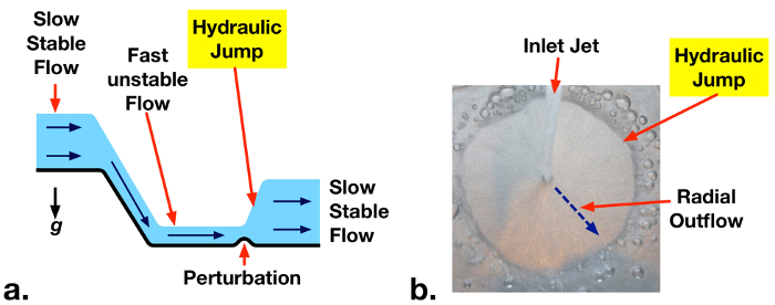
Abbildung 1: a. hydraulische springen zu einem instabilen Hochgeschwindigkeits-Fluss stromabwärts vom einem Abflußkanal durch eine leichte Störung auftreten. b. Beispiel hydraulischer Sprung in radialen Abfluss von Wasser aus einem Haushalt Hahn.

Principles

In weit offenen Kanal fließt Flüssigkeit ist nur durch eine feste Untergrenze beschränkt und die Oberseite der Atmosphäre ausgesetzt ist. Auf einem Abschnitt der eine offene Wasserführung, Einlass und Auslass Transport von Masse und Impuls (Abb. 2) auszugleichen kann eine Lautstärke Analyse durchgeführt werden. Wenn die Geschwindigkeiten in den Einlass und Auslass der Lautstärke einheitlich angenommen werden (V1 und V2 bzw.) eine stetige Masse fließen dann mit entsprechenden flüssige tiefen H1 und H2, Gleichgewicht reduziert auf:

Equation 1(1)

Die X-Richtung Schwung Analyse dieser Lautstärke gleicht Streitkräfte aus dem hydrostatischen Druck (durch flüssige Tiefe) mit dem Einlass und Auslass Dynamik Durchflussmengen (Eqn. 2). Die Druckkräfte wirken nach innen auf beiden Seiten von der Lautstärke und sind gleich auf das spezifische Gewicht der Flüssigkeit (Dichte Flüssigkeit Mal Erdbeschleunigung: ρg), multipliziert mit der flüssigen Durchschnittstiefe auf jeder Seite (H12, H 22), multipliziert die Höhe, über die der Druck wirkt auf jeder Seite (H1, H2). Dies führt zu der quadratischen Ausdruck auf der linken Seite des Eqn. 2. Die Dynamik-Volumenströme durch jede Seite (Eqn. 2, rechts) entsprechen der Massenströme von Flüssigkeit durch die Lautstärke (in: Equation 2 , aus: Equation 3 ) multipliziert mit der Flüssigkeiten Geschwindigkeiten (V1, V2).

Equation 4(2)

EQN. 1 kann in Eqn. 2 V2zu beseitigen ersetzt werden. Die Froude-Zahl (Equation 5) auch ersetzt werden kann, entspricht die relative Stärke der Zufluss Impuls zur hydrostatischen Kräfte. Der resultierende Ausdruck kann als angegeben werden:

Equation 6(3)

Diese kubische Gleichung hat drei Lösungen. Einer ist H1 = H2, verleiht das normale Verhalten der offene Kanal (Einlass Tiefe = Steckdose Tiefe). Eine zweite Lösung gibt eine negative Flüssigkeitsstand, die unphysikalisch, und beseitigt werden kann. Die restliche Lösung ermöglicht eine Erhöhung der Tiefe (hydraulischer Sprung) oder eine Abnahme in der Tiefe (hydraulische Depression), je nach dem Einlass Froude Zahl. Wenn der Einlass Froude-Zahl (Fr1) größer als eins ist, nennt man der Fluss überkritischen (instabil) und hat hohe mechanischen Energie (kinetische + Schwerkraft Lageenergie). In diesem Fall kann ein hydraulischer Sprung spontan oder durch eine Störung der Strömung bilden. Die hydraulischen Sprung zerstreut mechanischen Energie in Wärme, die kinetische Energie deutlich zu reduzieren und leicht erhöht die potentielle Energie der Strömung. Die daraus resultierende Auslaufhöhe Eqn. 4 (eine Lösung für Eqn. 3) erteilt. Eine hydraulische Depression kann nicht auftreten, wenn Fr1 > 1 weil es mechanischen Energie des Flusses erhöhen würde, den zweiten Hauptsatz der Thermodynamik verletzt.

Equation 7(4)

Die Stärke der hydraulische Sprünge erhöht mit Einlass Froude Zahl. Da Fr1 erhöht, erhöht sich das Ausmaß der H2/h1 und ein größerer Teil der Einlass kinetische Energie wird als Wärme [1] abgeführt.

Figure 2
Abbildung 2: Die Lautstärke eines Teils der eine offene Wasserführung, enthält einen hydraulischen Sprung. Einlass und Masse und Dynamik sind Fördermengen pro Einheit Breite angegeben. Hydrostatische Kräfte pro Einheit Breite im unteren Diagramm angegeben.

Procedure

Hinweis: Dieses Experiment verwendet eine relativ starke Tauchpumpe. Die Pumpe sollte nur ein Fi-Schutzschalter Steckdose elektrische Risikominimierung angeschlossen werden. Stellen Sie sicher, dass keine anderen a/c powered Geräte in der Nähe des Experiments tätig sind. 1. Herstellung von offene Wasserführung Anlage und Tank (siehe Diagramm und Foto, Abb. 3) Schnittlängen von ~6.0 mm dicken × 9,5 cm breit klar Acrylplatte mit folgenden Längen: 2 × 15 cm, 2 × 25 cm, 1 × 34 cm, 1 × 41 cm (Abb. 3a). Es wird empfohlen, eine Tabelle zu verwenden gesehen oder Laser-Cutter um sicherzustellen, dass die Kanten relativ flach sind und die Blätter haben gleich Dicke. Schneiden Sie Löcher in den unteren rechten Ecken von zwei 60 × 45 cm Acrylplatten, montieren Sie den Durchflussmesser (Abb. 3a). Schneiden Sie ein Loch auf der oberen rechten Seite des vorderen Blattes der Stromregelventil installieren. Verwenden Sie Acryl Zement (z.B., SCIGRIP 16), um die Acryl-Paneele zu verbinden, wie in Abb. 3a angegeben. Sorgen Sie für ausreichende Belüftung und tragen Sie Handschuhe beim Umgang mit des Acryl Zements. Es ist hilfreich, Zement mit einer Nadel Spritze auftragen und Klebeband verwenden, um Platten während der Härtung zu positionieren. Lassen Sie den Zement für 24-48 Stunden zu heilen. Installieren Sie den Durchflussmesser auf der Frontplatte und Affix mit den mitgelieferten Schrauben. Installieren Sie 1 NPT auf ½ NPT reduzierenden Beschläge an den Durchflussmesser Einlass und Auslass-Anschlüssen. Installieren Sie ½ NPT auf 0,5 Zoll Innendurchmesser Stacheldraht passende Adapter für die Armaturen. Installieren Sie ein 0,5 Zoll. ID und ein 0,75 Zoll. ID Stacheldraht Anbau an den Schieber (Flow-Rate-Regler). Schließen Sie den Stacheldraht passend zur Tauchpumpe mit ~ 20 cm Länge Schlauch so, dass der Ventilgriff mit dem Loch auf der Oberseite rechts von der Acryl-Gehäuse (Abb. 3 b-c). Legen Sie die Pumpe in den unteren Behälter, und installieren Sie das Ventil zu, so dass die Ventilspindel das Befestigungsloch durchläuft und der Griff außerhalb des Gehäuses (Abb. 3 c ist). Fügen Sie eine vertikale Acrylplatte in der Nähe der Einlassabschnitt der Flow Anlage, sodass befindet sich etwa eine 5,0 mm Öffnung unten (Abb. 3 b-c). Diese Komponente kann wird als das Schleusentor, und angehoben und auf Flow aus dem oberen Becken um den Kanal zu Steuern gesenkt werden. Füllen Sie das Oberbecken mit einem Scheuerschwamm Edelstahlwolle locker. Auf diese Weise Meeresarm-Wasser-Strömung über den Kanal gleichmäßig zu verteilen. Der Durchflussmesser-Bucht mit einer Länge von weichen Kunststoffschlauch der Ventilausgang herstellen. Die Durchflussmesser Steckdose an den oberen Behälter mit Kunststoffschlauch anschließen. Sicherstellen Sie, dass der Schlauch Einlass zu den oberen Behälter gut verankert ist, so dass es nicht ausschwenken, wenn die Pumpe eingeschaltet ist. Füllen Sie den unteren Behälter mit Wasser. 2. durchführen experiment Messen Sie die Höhe der Lücke unter dem Tor mit einem Lineal und bezeichnen Sie den Wert als H-1. Schalten Sie die Pumpe, und passen Sie die Durchflussmenge mit Hilfe des Ventils zu verschiedenen Durchflussraten (5-15 l min-1). Verwenden Sie ein Lineal, um die flüssige Tiefe flussabwärts vom Tor (H2) für jeden Fall messen. Beobachten Sie die Formen der hydraulische Sprünge qualitativ, bilden bei unterschiedlichen Strömungsgeschwindigkeiten. Achten Sie auf die Mindestgrenze Durchflussmenge für Bildung eines hydraulischen Sprunges. Schärfer, größere Amplitude (H2 -H-1), Sprünge sollte bei höheren Strömungsgeschwindigkeiten auftreten. (3) Datenanalyse Berechnen Sie für jeweils Flow Rate die Einlass-Geschwindigkeit, V1, von der Volumenstrom. wo ist das Saugvermögen und W ist die Kanalbreite. Bewerten den Einlass Froude-Zahl () und theoretische nachgelagerten flüssige Tiefe für jeden Fall (Eqn. 4). Vergleichen Sie diese Werte mit gemessenen nachgelagerten Sprung tiefen. Abbildung 3 : A. Schaltplan und Abmessungen der Anlage Struktur. b. Flussdiagramm des hydraulischen Sprung Anlage. c. Etikettierte Fotos der Versuchsanlage.

Results

Upstream Froude numbers (Fr1) and measured and theoretical downstream depths are summarized in Table 1. The measured threshold inlet flow rate for formation of a hydraulic jump corresponds to Fr1 = 0.9 ± 0.3, which matches the theoretical value of 1. At supercritical flow rates (Fr1 > 1) predicted downstream depths match theoretical values (Eqn. 4) within experimental uncertainty.

Table 1 – Measured upstream Froude numbers (Fr1) and downstream liquid depths for H1 = 5 ± 1 mm

Liquid Flow Rate

(Equation 9, l min-1)

Upstream Froude Number (Fr1) Measured Downstream Depth (H2) Predicted Downstream Depth (H2) Notes
6.0   ± 0.5 0.9 ± 0.3 5 ± 1 5 ± 1 Threshold Froude number for hydraulic jump
11.0 ± 0.5 1.7 ± 0.5 11 ± 1 10 ± 2
12.0 ± 0.5 1.9 ± 0.6 12 ± 1 11 ± 2
13.5 ± 0.5 2.1 ± 0.6 14 ± 1 13 ± 2

Photographs of the hydraulic jumps from the above cases are presented in Fig. 4. No jump is observed for Equation 9 = 6.0 l min-1 (Fr1 = 0.9). Jumps are observed for the two other cases with Fr1 > 1. A stronger, higher amplitude, jump is observed at the higher flow rate supercritical case.

Figure 4
Figure 4: Photograph of hydraulic jumps, showing critical condition (no jump, Fr1 = 0.9) and jumps at Fr1 = 1.9, 2.1.

Applications and Summary

This experiment demonstrated the phenomena of hydraulic jumps that form at supercritical conditions (Fr > 1) in open channel flows. An experimental facility was constructed to observe hydraulic jump phenomena at varying flow rates. Downstream liquid depths were measured and matched with theoretical predictions.

In this experiment, the maximum reported inlet Froude number was 2.1. The pump was rated to deliver significantly higher flow rates, but resistance in the flow meter limited measurable flow rates to ~14 l min-1. In future experiments, a pump with a greater head rating or a lower pressure drop flow meter may enable a broader range of studied conditions.

Hydraulic jumps are often engineered into hydraulic systems to dissipate fluid mechanical energy into heat. This reduces the potential for damage by high velocity liquid jetting from spillways. At high channel flow velocities, sediment can be lifted up from streambeds and fluidized. By reducing flow velocities, hydraulic jumps also reduce the potential for erosion and scouring around pilings. In water treatment plants, hydraulic jumps are sometimes used to induce mixing and aerate flow. The mixing performance and gas entrainment from hydraulic jumps can be observed qualitatively in this experiment.

For all of these applications, momentum analyses across hydraulic jumps, as discussed here, are key tools for predicting hydraulic system behavior. Similarly, scale model experiments such as those demonstrated in this project, can guide the design of open-channel flow geometries and hydraulic equipment for large-scale engineering applications.

References

  1. Cimbala, Y.A. Cengel, Fluid Mechanics Fundamentals and Applications, 3rd edition, McGraw-Hill, New York, NY, 2014.

Transcript

A hydraulic jump is a phenomenon that occurs in fast-moving open flows when the flow becomes unstable. When a jump occurs, the height of the liquid surface increases abruptly resulting in an increased depth and decreased average flow velocity downstream. An important side effect of this phenomenon is that much of the kinetic energy in the upstream flow is dissipated as heat. Although hydraulic jumps often arise naturally, such as in rivers or the flow into a household sink, they are also purposely engineered into large waterworks to minimize erosion, or increase mixing. This video will illustrate the principles behind hydraulic jumps in a straight channel and then demonstrate the phenomenon experimentally using a small-scale open channel flow facility. After analyzing the results, some applications of hydraulic jumps will be discussed.

Consider the flow in a wide, straight section of an open channel where a hydraulic jump occurs and construct a control volume on a sluice around the jump. If the flow velocity is uniform at the inlet and outlet, conservation of mass yields a simple relation between upstream and downstream fluid depths. Depth multiplied by velocity is constant. A second relation can be found by considering conservation of momentum. Mass transported across the input and output carries momentum with it equal to the corresponding mass flux multiplied by the flow velocity. Hydrostatic forces on the surface of the control volume also contribute to the momentum balance and must be included. These forces are equal to the average pressure on the surface multiplied by the area. At this point, it is useful to introduce the Froude number, a dimensionless quantity named after the English engineer and hydrodynamicist, William Froude. The Froude number characterizes the relative strength of fluid momentum to hydrostatic forces. Now, if the momentum relation is rewritten in terms of the Froude number, with the output velocity eliminated by substitution using the mass relation, the result is a cubic equation in terms of the ratio of downstream and upstream depths. This equation can be simplified by factoring out the trivial solution where the upstream and downstream depths are equal. The two remaining solutions are easily found using the quadratic equation, but the negative solution can be eliminated since it is non-physical. The remaining solution corresponds to an increase in depth, a hydraulic jump, or a decrease in depth, a hydraulic depression, based on the value of the upstream Froude number. If the upstream Froude number is greater than one, the flow has a high mechanical energy and is supercritical or unstable. A hydraulic depression cannot form in this regime because it would increase mechanical energy and violate the second law of thermodynamics. On the other hand, a hydraulic jump can form, either spontaneously or due to some disturbance in the flow. An input Froude number of one represents the minimum threshold for the onset of a hydraulic jump. Hydraulic jumps dissipate mechanical energy into heat, and significantly reduce the kinetic energy, while slightly increasing the potential energy of the flow. As the Froude number increases, so does the ratio of downstream to upstream depths and the amount of kinetic energy dissipated as heat. Now that we understand the principles behind hydraulic jumps, let’s examine them experimentally.

First, fabricate the open channel flow facility as described in the text. The facility has an upper and lower reservoir connected by an open channel. Water pumped from the lower reservoir is deposited in the upper reservoir with the flow rate controlled and measured by a valve and flow meter in line with the pump. Steel wool in the upper reservoir helps to evenly distribute the water across the width of the section, and the adjustable sluice gate controls the fluid depth as it enters the channel. After flowing through the channel, the fluid is deposited back into the lower reservoir. When the flow facility is assembled, set it up on a bench and remove any nearby electronic devices. Plug the pump into a GFCI outlet to minimize the risk of electrical shock, and then fill the lower reservoir with water. You are now ready to perform the experiment.

Adjust the sluice gate to approximately five millimeters. Measure the final height of the gap underneath the sluice gate using a ruler, and record this distance as the upstream flow depth, H1. When you are finished, turn on the pump and use the valve to maximize the flow rate without exceeding the scale on the flow meter. Use the ruler again to measure the fluid depth after the hydraulic jump. Record the flow rate, along with this second distance which is the downstream flow depth, H2. Before continuing, observe the shape of the hydraulic jump. You should notice larger, more abrupt transitions for higher flow rates, and smaller, more gradual transitions for lower flow rates. Now, repeat your measurements and observations for successively lower flow rates. Try to determine the minimum threshold flow rate for the formation of a hydraulic jump. Once you have found the threshold flow rate, you are ready to analyze the results.

For each volumetric flow rate, you should have a measurement of the downstream fluid depth. The upstream depth is the same for all cases. Complete the following calculations for each measurement and propagate uncertainties along the way. First, determine the inlet flow velocity. Divide the volumetric flow rate by the channel width and upstream depth. Next, evaluate the upstream Froude number using the definition given before, and substituting in the acceleration due to gravity, as well as the upstream height and velocity. Now, use the Froude number and the non-trivial solution for the jump height to calculate the theoretical downstream depth. Compare the theoretical prediction with the measured downstream depth. At supercritical flow rates, the predictions match the measured depths within experimental uncertainty. Look at your results for the threshold flow rate. Within experimental uncertainty, the Froude number is one, as we anticipated from the theoretical analysis. The rate of mechanical energy loss through the hydraulic jump can also be calculated from these data. First, calculate the mechanical energy of the fluid flowing into the jump, which is the sum of kinetic and potential energy flow rates at the inlet. Now, determine the output energy rate in the same way, but with values at the outlet. The rate of mechanical energy dissipation to heat is the difference between the input and output rates. In this experiment, the energy loss rate can reach about 40% of the inlet energy, or higher. These results highlight the effectiveness of momentum analyses and scale model experiments for understanding and predicting the behavior of hydraulic systems. Now let’s look at some other ways hydraulic jumps are utilized.

Hydraulic jumps are an important natural phenomenon with many engineering applications. Hydraulic jumps are often engineered into hydraulic systems to dissipate fluid mechanical energy into heat. This reduces the potential for damage by high velocity liquid jetting from spillways. At high channel flow velocities, sediment can be lifted up from streambeds and fluidized. By reducing flow velocities, hydraulic jumps also reduce the potential for erosion and scouring around pilings. In water treatment plants, hydraulic jumps are sometimes used to induce mixing and aerate flow. The mixing performance and gas entrainment from hydraulic jumps can be observed qualitatively in this experiment.

You’ve just watched JoVE’s introduction to hydraulic jumps. You should now understand how to use a control volume approach to predict the flow behavior, and how to measure this behavior using an open channel flow facility. You’ve also seen some practical uses for engineering hydraulic jumps in real applications. Thanks for watching.

Tags

Cite This
JoVE Science Education Database. JoVE Science Education. Hydraulic Jumps. JoVE, Cambridge, MA, (2023).